Table of Contents
Advertisement
Quick Links
This publication, photographs, illustrations and software are
under the protection of international copyright laws and all
rights reserved. It does not allow any reproduction of this
manual, content and any materials contained herein without
the written consent of the authentic manufacturer.
The information in this manual is subject to change without
notice. The manufacturer does neither represent nor warrant
the contents hereof; and specifically disclaims any implied
warranties of merchantability or fitness for any particular pur-
pose. Furthermore, the manufacturer reserves the right to
revise and change this publication from time to time, without
the obligation of notifying any person of such revision or
changes.
Trademarks
IBM, VGA, and PS/2 are registered trademarks of Interna-
tional Business Machines.
Intel, Pentium, Pentium-II, and MMX are registered trade-
marks of Intel Corporation.
Microsoft, MS-DOS and Windows 95/98/NT/2000 are regis-
tered trademarks of Microsoft Corporation.
PC-cillin and ChipAwayVirus are trademarks of Trend Micro
Inc.
AMI is a trademark of American Megatrends, Inc.
MediaRing Talk is a registered trademark of MediaRing Inc.
3Deep is a registered trademark of E-Color Inc.
It has been acknowledged that all mentioned brands or prod-
uct names are trademarks or registered trademarks of their
respective holders.
Copyright © 2001
All Rights Reserved
P4ITA2, V1.0
Advertisement
Table of Contents

Related Manuals for ECS P4ITA2


Summary of Contents for ECS P4ITA2
- Page 1 MediaRing Talk is a registered trademark of MediaRing Inc. 3Deep is a registered trademark of E-Color Inc. It has been acknowledged that all mentioned brands or prod- uct names are trademarks or registered trademarks of their respective holders. Copyright © 2001 All Rights Reserved P4ITA2, V1.0...
- Page 2 Federal Communications Commission (FCC) This equipment has been tested and found to comply with the limits for a Class B digital device, pursuant to Part 15 of the FCC Rules. These limits are designed to provide reasonable protection against harmful interference in a residential installation. This equipment gen- erates, uses, and can radiate radio frequency energy and, if not installed and used in accordance with the instructions, may cause harmful interference to radio communications.
-
Page 3: Table Of Contents
Table of Contents Chapter 1: Introduction ............. 1 Key Features............. 2 Package Contents ............. 5 Static Electricity Precautions........6 Pre-Installation Inspection ......... 6 Chapter 2: Mainboard Installation ..........7 Mainboard Components..........8 I/O Ports ..............9 Installing the Processor..........9 Installing Memory Modules ........ -
Page 5: Chapter 1: Introduction
(FSB) speeds up to 400 MHz and data bus bandwidths up to 3.2 GB/s. The P4ITA2 incorporates the Intel Tehama 850 Northbridge and Intel 82801BA (ICH2) Southbridge chipsets, combining support for dual- channel RAMBUS DRAM (RDRAM), 2X/4X AGP (1.5V only), and the AC 97 codec. -
Page 6: Key Features
Key Features This mainboard has these key features: Socket 423 Processor ♦ The PGA Socket 423 ♦ Accommodates Intel Pentium 4 CPUs ♦ Supports a front-side bus (FSB) of 400 MHz ♦ Supports 3.2 GB/s data bus bandwidth Chipset Intel’s innovative Tehama 850 Northbridge and 82801 Southbridge chipsets are based on an innovative and scaleable architecture with proven reliability and performance. - Page 7 ♦ The P4ITA2 includes a 4xAGP slot that provides four times the bandwidth of the original AGP specification. AGP tech- nology provides a direct connection between the graphics sub- system and the processor so that the graphics do not have to compete for processor time with other devices on the PCI bus.
- Page 8 BIOS Firmware This mainboard uses AMI BIOS that enables users to configure many system features including the following: ♦ Power management ♦ Wake-up alarms ♦ CPU parameters and memory timing ♦ CPU and memory timing The firmware can also be used to set parameters for different proces- sor clock speeds.
-
Page 9: Package Contents
Package Contents Your mainboard package contains the following items: The mainboard The User’s Guide One diskette drive ribbon cable and bracket One IDE drive ribbon cable and bracket One auto-install software support CD Retention modules (already mounted on the board) Two CPU retention brackets Two dummy Rambus DRAM modules (already inserted in RIMM slots) -
Page 10: Static Electricity Precautions
Static Electricity Precautions Components on this mainboard can be damaged by static electricity. Take the following precautions when unpacking the mainboard and installing it in a system. 1. Keep the mainboard and other components in their original static - proof packaging until you are ready to install them. 2. -
Page 11: Chapter 2: Mainboard Installation
Chapter 2 Mainboard Installation To install this mainboard in a system, follow the procedures in this chapter: Identify the mainboard components Install a CPU Install two or more system memory modules Verify that all jumpers or switches are set correctly Install the mainboard in a system chassis (case) Connect any extension brackets or cables to connecting headers on the mainboard... -
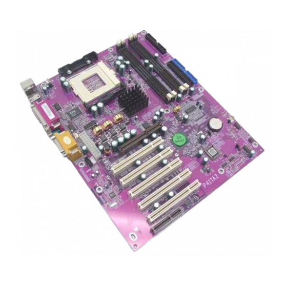
Page 12: Mainboard Components
Mainboard Components Note: Any jumpers on your mainboard that do not appear in this il- lustration are for testing only. -
Page 13: I/O Ports
I/O Ports The backplane of the mainboard has a full set of I/O ports: PS/2 Mouse Parallel Port Game/MIDI Port COM2/4 Line Out Jack PS/2 Keyboard Microphone Jack LIne In Jack USB Ports Serial Port COM1/3 1. Use the upper PS/2 port to connect a PS/2 pointing de- vice. - Page 14 CPU Installation Procedure The following illustration shows CPU installation components: Retention modules Locking lever Socket 423 Pin-1 corner Follow these instructions to install the CPU: 1. Pull the CPU socket locking lever away from the socket to unhook it and raise the locking lever to the upright position.
-
Page 15: Installing Memory Modules
Installing Memory Modules This mainboard accommodates 184-pin 2.5V unbuffered Rambus DRAM (RDRAM) memory modules. The memory chips must be standard or registered RDRAM. The memory bus runs at 400 MHz. Installation Procedure The mainboard has four RIMM (Rambus DIMM) slots that accommo- date up to 2 GB of memory. -
Page 16: Jumper Settings
After installing your RIMM modules, insert the C- RIMM modules in the unoccupied slots: Jumper Settings Jumper JBAT1 – enables you to clear the BIOS: 1. Turn the system off. 2. Remove all ATX power connectors. 3.Short pins 2 and 3 on JBAT1. 4.Return the jumper to the normal setting. -
Page 17: Panel Connector
Jumper 1 & Jumper 2 – enable this jumper if you want keyboard activity to turn on the computer. Setting (default) Jumper Type Description JP1 & 3 pin Keyboard 1-2: Enable power on 3 pin 2-3: Disable Jumper 12 – This jumper enables or disables the onboard audio codec. -
Page 18: Other Devices Installation
Other Devices Installation Floppy Diskette Drive Installation The mainboard has a floppy diskette drive (FDD) interface ships with a diskette drive ribbon cable that supports one or two floppy diskette drives. You can install a 5.25-inch drive and a 3.5-inch drive with various capacities. - Page 19 4 x AGP Slot The 4xAGP slot is used to install a graphics adapter that supports the 4xAGP specification and has a 4xAGP edge connector. The 4xAGP slot only supports 1.5V 4xAGP and 2xAGP cards. CNR Slot This slot is used to insert CNR cards including LAN, Modem, and Audio functions.
-
Page 20: Connecting Optional Devices
Connecting Optional Devices WOL1/WOM1: Wake On LAN/Wake On Modem If you have installed a LAN card, use the cable provided with the card to plug into the mainboard WOL1 connector. This enables the Wake On LAN (WOL) feature. When your system is in a power-saving mode, any LAN signal automatically resumes the system. - Page 21 JIR1: Consumer infrared port The mainboard supports a Consumer Infrared (CIR) data port. Infrared ports allow the wireless exchange of information between your com- puter and similarly equipped devices such as printers, laptops, Personal Digital Assistants (PDAs), and other computers. Signal Name Signal Name CIR receive...
-
Page 22: Chapter 3: Bios Setup Utility
Chapter 3 BIOS Setup Utility Introduction The BIOS Setup Utility records settings and information about your computer such as the date and time, the kind of hardware installed, and various config uration settings. Your computer uses this informa- tion to initialize all the components when booting up and functions as the basis for coordination between system components. -
Page 23: Running The Setuputility
Running the Setup Utility Each time your computer starts, before the operating system l o ads, a message appears on the screen that prompts you to “Hit <DEL> if you want to run SETUP”. When you see this message, press the Delete key and the Main menu page of the Setup Utility appears on your monitor. -
Page 24: Standard Cmos Setup Page
Standard CMOS Setup Page This option displays a table of items defining basic information about your system. AMIBIOS SETUP – STANDARD CMOS SETUP (C) 2000 American Megatrends, Inc. All Rights Reserved Date (mm/dd/yy) : Tue Oct 24, 2000 Time (hh/mm/ss) : 14:26:53 32Bit Type Size Cyln Head WPcom Sec Mode Mode Mode Mode... -
Page 25: Advanced Setup Page
Advanced Setup Page This option displays a table of items that define advanced information about your system. AMIBIOS SETUP – ADVANCED SETUP (C) 2000 American Megatrends, Inc. All Rights Reserved Quick Boot Enabled Boot Device IDE-0 Boot Device Floppy Boot Device CDROM Try Other Boot Devices S.M.A.R.T. - Page 26 If you have two diskette drives installed Floppy Drive and you enable this item, drive A becomes Swap drive B and drive B becomes drive A. If you enable this item, your system will Floppy Drive check all floppy disk drives at start up. Seek Disable this item unless you are using an old 360KB drive.
-
Page 27: Power Management Setup Page
Power Management Setup Page This page sets some of the parameters for system power management operation. AMIBIOS SETUP – POWER MANAGEMENT SETUP (C) 2000 American Megatrends, Inc. All Rights Reserved Power Management/APM Enabled ACPI Aware O/S Standby Time Out Disabled Suspend Time Out Disabled Wake Up on Ring... - Page 28 The system can be turned off with a software Wake Up on command. If you enable this item, the system Ring can automatically resume if there is an incom- ing call on the Fax/Modem. You must use an ATX power supply in order to use this feature. The system can be turned off with a software Wake Up on command.
-
Page 29: Pci / Plug And Play Setup Page
PCI / Plug and Play Setup Page This page sets some of the parameters for devices installed on the PCI bus and devices that use the system plug and play capability. AMIBIOS SETUP – PCI / PLUG AND PLAY SETUP (C) 2000 American Megatrends, Inc. -
Page 30: Load Optimal Settings
Load Optimal Settings If you select this item and press Enter a dialog box appears. If you press Y, and then Enter, the Setup Utility loads a set of fail-safe de- fault values. These default values are not very demanding and they should allow your system to function with most kinds of hardware and memory chips. - Page 31 Use this item to enable or disable the onboard Onboard LPT1 parallel port, and to assign a port address. Parallel Port The Auto setting will detect and available ad- dress. Use this item to set the parallel port mode. You Parallel Port can select SPP (Standard Parallel Port), ECP (Ex- Mode...
-
Page 32: Cpu Pnp Setup Page
CPU PnP Setup Page This page helps you manually configure the mainboard for the CPU. The system will automatically detect the type of installed CPU and make the appropriate adjustments to the items on this page. AMIBIOS SETUP – CPU PnP SETUP ©2000 American Megatrends, Inc. -
Page 33: Hardware Monitor Page
Hardware Monitor Page This page sets some of the parameters for the hardware monitoring function of this mainboard. AMIBIOS SETUP – HARDWARE MONITOR (C) 2000 American Megatrends, Inc. All Rights Reserved *** Hardware Monitor *** System Temperature 38°C/100°F CPU Temperature 58°C/138°F System Fan Speed 0 RPM... -
Page 34: Chapter 4: Using The Mainboard Software
Chapter 4 Using the Mainboard Software About the Software CD-ROM The support software CD-ROM that is included in the mainboard package contains all the dr ivers and utility programs needed to prop- erly run the bundled products. Below you can find a brief description of each software program, and the location for your mainboard version. -
Page 35: Auto-Installing Under Windows 98
A u t o - i n s t a l l i n g u n d e r W i n d o w s 9 8 The Auto-install CD-ROM makes it easy for you to install the drivers and software for your mainboard. - Page 36 Browse CD The Browse CD button is the standard Windows command that allows you to open Windows Explorer and show the contents of the support Before installing the software from Windows Explorer, look for a file named README.TXT, INSTALL.TXT or something similar. This file may contain important information to help you install the software correctly.
- Page 37 Running Setup Follow these instructions to install device drivers and software for the mainboard: 1. Click Setup. The installation program begins Mainboard ID Note: The following screens are examples only. The screens and driver lists will be different according to the mainboard you are installing.
- Page 38 2. Click Next. The following screen appears: Check the box next to the items you want to install. The de- fault options are recommended. Click Next run the Installation Wizard. An item installation screen appears: 5. Follow the instructions on the screen to install the items. Drivers and software are automatically installed in sequence.
-
Page 39: Drivers Installation
Drivers Installation Follow these instructions to install device drivers and software for the mainboard: Audio Drivers and Software Most of the sub-folders in this folder are empty, with a short README file giving directions to alternate folders for the appropriate software. Installation for Windows 2000/98/98SE/ME/95 install audio... - Page 40 INF Files This folder has software and drivers for the IDE that is inte- grated on this mainboard. Drivers are provided for Windows 2000/98/98SE/ME/95 and Windows NT. Installation for Windows 2000/98/98SE/ME/95 To install the IDE drivers, go to the directory \INTEL\INST\; then run SETUP.EXE to install the IDE driver for your operat- ing system.
-
Page 41: Utility Software Reference
Utility Software Reference All the utility software available from this page is Windows compliant. They are provided only for the convenience of the users. The follow- ing software is furnished under license and may only be used or copied in accordance with the terms of the license. Note: This software is subject to change at anytime without prior notice. - Page 42 stall the application software. CD Ghost The CD Ghost software enables you to create a virtual cabinet of CD-ROM drives on your system to help you categorize and organize your CD collection. A user-friendly interface assists you in quickly creating images of both CDs and DVDs onto your system.
- Page 43 WinDVD (optional) Go to the directory \UTILITY\WINDVD; then run SETUP.EXE to install the application software. The WinDVD software is not free. Before you install, you need to register and get the serial number first.