MULTIQUIP Whiteman Series Operation Manual
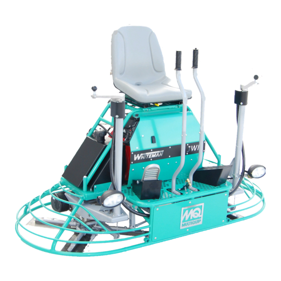
Ride-on power trowels (honda gx690rtaf gasoline engine)
Hide thumbs
Also See for Whiteman Series:
- Operation and parts manual (64 pages) ,
- Operation manual (48 pages) ,
- Setup and adjustment (34 pages)
Table of Contents
Advertisement
Quick Links
OPERATION MANUAL
SERIES
MODELS
JWN24HTCSL
JWN24HSCSL
RIDE-ON POWER TROWELS
(HONDA GX690RTAF GASOLINE ENGINE)
STARTING S/N VB0206952
Revision #3 (08/30/19)
To find the latest revision of this publication or
associated parts manual, visit our website at:
www.multiquip.com
THIS MANUAL MUST ACCOMPANY THE EQUIPMENT AT ALL TIMES.
PN: 23624
Advertisement
Table of Contents

Related Manuals for MULTIQUIP Whiteman Series


Summary of Contents for MULTIQUIP Whiteman Series
- Page 1 RIDE-ON POWER TROWELS (HONDA GX690RTAF GASOLINE ENGINE) STARTING S/N VB0206952 Revision #3 (08/30/19) To find the latest revision of this publication or associated parts manual, visit our website at: www.multiquip.com THIS MANUAL MUST ACCOMPANY THE EQUIPMENT AT ALL TIMES. PN: 23624...
-
Page 2: Proposition 65 Warning
PROPOSITION 65 WARNING PAGE 2 — JWN-SERIES RIDE-ON POWER TROWEL • OPERATION MANUAL — REV. #3 (08/30/19) -
Page 3: Silicosis/Respiratory Warnings
SILICOSIS/RESPIRATORY WARNINGS WARNING WARNING SILICOSIS WARNING RESPIRATORY HAZARDS Grinding/cutting/drilling of masonry, concrete, metal and Grinding/cutting/drilling of masonry, concrete, metal and other materials with silica in their composition may give other materials can generate dust, mists and fumes off dust or mists containing crystalline silica. Silica is a containing chemicals known to cause serious or fatal basic component of sand, quartz, brick clay, granite and injury or illness, such as respiratory disease, cancer,... -
Page 4: Table Of Contents
TABLE OF CONTENTS JWN Series Ride-On Trowel Proposition 65 Warning ........... 2 Silicosis/Respiratory Warnings ........ 3 Table of Contents ............. 4 Training Checklist ............ 6 Daily Pre-Operation Checklist ......... 7 Safety Information ..........8–14 Lifting and Transporting ........15–17 Specifications ............18 Dimensions ............ - Page 5 NOTES JWN-SERIES RIDE-ON POWER TROWEL • OPERATION MANUAL — REV. #3 (08/30/19) — PAGE 5...
-
Page 6: Training Checklist
TRAINING CHECKLIST Training Checklist Description Date Read operation manual completely. Machine layout, location of components, checking of engine oil levels. Fuel system, refueling procedure. Operation of spray and lights. Operation of controls (machine not running). Safety controls, safety stop switch operation. -
Page 7: Daily Pre-Operation Checklist
DAILY PRE-OPERATION CHECKLIST Daily Pre-Operation Checklist Engine oil level Condition of blades Blade pitch operation Safety stop switch operation Steering control operation JWN-SERIES RIDE-ON POWER TROWEL • OPERATION MANUAL — REV. #3 (08/30/19) — PAGE 7... -
Page 8: Safety Information
SAFETY INFORMATION Do not operate or service the equipment before reading Potential hazards associated with the operation of this the entire manual. Safety precautions should be followed equipment will be referenced with hazard symbols which at all times when operating this equipment. may appear throughout this manual in conjunction with Failure to read and understand the safety safety messages. - Page 9 SAFETY INFORMATION SAFETY DECALS Decals associated with the safe operation of this equipment are defi ned below. WARNING DANGER Lifting/Crush Hazard Flying Objects Hazard NEVER allow any person to stand DO NOT disassemble spring cylinders without underneath the trowel while lifting. qualified service personnel.
- Page 10 „ NEVER use accessories or attachments that are not „ Avoid wearing jewelry or loose fi tting clothes that may recommended by Multiquip for this equipment. Damage snag on the controls or moving parts as this can cause to the equipment and/or injury to user may result.
- Page 11 SAFETY INFORMATION TROWEL SAFETY NOTICE DANGER „ ALWAYS keep the machine in proper running condition. „ Engine fuel exhaust gases contain poisonous carbon „ Fix damage to machine and replace any broken parts monoxide. This gas is colorless and odorless, and can immediately.
- Page 12 SAFETY INFORMATION FUEL SAFETY WARNING „ ALWAYS wear safety glasses when DANGER handling the battery to avoid eye irritation. „ DO NOT start the engine near spilled fuel or combustible The battery contains acids that can cause fl uids. Fuel is extremely fl ammable and its vapors can injury to the eyes and skin.
- Page 13 SAFETY INFORMATION TOWING SAFETY NOTICE „ The easiest way to lift the trowel is to utilize the lift loops CAUTION that are welded to the frame. These lift loops are located „ Check with your local county or state safety to the left and right sides of the operator’s seat.
- Page 14 SAFETY INFORMATION Emission Control Label „ Trailer should be adjusted to a level position at all times when towing. The emission control label is an integral part of the emission „ Raise and lock trailer wheel stand in up position when system and is strictly controlled by regulation(s).
-
Page 15: Lifting And Transporting
Failure to comply with these lifting the parts manual included with your trowel for part numbers, instructions may result in sling failure and order from your Multiquip parts dealer or importer. and severe personal injury or death. Only qualified personnel with proper training should perform this procedure. - Page 16 LIFTING AND TRANSPORTING The Occupational Safety and Health Administration (OSHA) Regulation 29 CFR Part 1926.251 (e)(8)—Removal from service requires that the slings be inspected prior to each use, and removed from service immediately if any of the following conditions are found: „...
- Page 17 LIFTING AND TRANSPORTING LIFTING PROCEDURE 2. Insert forklift forks through the loops at the ends of the lifting slings (Figure 2). Keep the slings as close The correct lifting slings (Figure 1) have been supplied with to vertical as possible. If the choke angle (Figure 3) is your trowel, in accordance to its weight per Occupational 120 degrees or less, the lifting strength of the slings Safety and Health Administration (OSHA) Regulation...
-
Page 18: Specifications
SPECIFICATIONS Table 2. Trowel Specifications Operating Weight 685 lb. (310.7 kg) Shipping Weight 885 lb. (401.4 kg) Fuel Tank Capacity 5 gallons (18.9 liters) Min. Rotor Speed (Dry Concrete) 180 rpm Path Width 75 in. (191 cm) Gearbox Oil Capacity 28 oz. -
Page 19: Dimensions
DIMENSIONS Figure 4. Trowel Dimensions Table 5. Trowel Dimensions Measurement in. (cm) (A) Length 77 (195.6) (B) Width 39 (99.1) (C) Height 46.75 (118.7) JWN-SERIES RIDE-ON POWER TROWEL • OPERATION MANUAL — REV. #3 (08/30/19) — PAGE 19... -
Page 20: General Information
This manual is included with the trowel at the time of shipping. Please contact your nearest Multiquip dealer for a replacement should the original manual become lost or damaged. BLADES The blades of the trowel finish the concrete as they are swirled around the surface. -
Page 21: Components
COMPONENTS (TROWEL) 1. Seat — The engine will not start unless the operator DANGER is seated. Add fuel to the tank only when the engine is 2. Steering Control Levers — Direct the unit forward, stopped and has had an opportunity to cool reverse, left, or right. - Page 22 COMPONENTS (TROWEL) 17. Rear Light — The JWN Series ride-on power trowel 23. Left-Side Spider — Consists of trowel arms, blades, has three 12-volt halogen lights. wear plate, and thrust collar. 18. Lift Loops — Located on both sides of the main frame. 24.
- Page 23 COMPONENTS (ENGINE) Figure 7. Engine Components INITIAL SERVICING 7. Spark Plug — Provides spark to the ignition system. Set the spark plug gap to 0.6–0.7 mm (0.028–0.031 inch) The engine (Figure 7) must be checked for proper Clean the spark plug once a week. lubrication and filled with fuel prior to operation.
-
Page 24: Setup
SETUP SEAT ASSEMBLY The purpose of this section is to assist the user in setting up a NEW trowel. If your trowel is already assembled (seat, The seat is not installed on the trowel for shipping purposes. handles, knobs, and battery), this section can be skipped. To attach the seat perform the following: NOTICE 1. -
Page 25: Inspection
INSPECTION ENGINE OIL LEVEL 3. If engine oil is low, remove the oil filler cap (Figure 8), and add the correct amount of engine oil to bring the oil to a NOTICE normal, safe level. Use oil as recommended in Table 6. ALWAYS check engine oil before each use. - Page 26 INSPECTION FUEL LEVEL DANGER Handle fuel safely. Motor fuels are highly flammable and can be dangerous if mishandled. NEVER smoke while refueling. NEVER attempt to refuel while the engine is running or hot. In the event of a fuel spill, DO NOT attempt to start the engine until the fuel residue has been completely wiped up and the area surrounding the engine is dry.
-
Page 27: Operation
OPERATION The instructions in this manual are provided as a basic 3. The right foot pedal (Figure 11) controls blade and guide to trowel operation, not a complete guide to concrete engine speed. The position of the foot pedal determines finishing. - Page 28 OPERATION STEERING 4. Insert the ignition key (Figure 13) into the ignition switch. Two control levers located in front of the operator’s seat provide directional control for the trowel. Table 7 illustrates the various directional positions of the joysticks and their effect on the ride-on trowel.
- Page 29 OPERATION Table 7. Control Lever Directional Positioning CONTROL JOYSTICK RESULT & DIRECTION Causes only the Move LEFT Joystick left side of the FORWARD ride-on trowel to move forward. Causes only the Move LEFT Joystick left side of the BACKWARD ride-on trowel to move backward.
-
Page 30: Maintenance
MAINTENANCE Yearly (500–600 Hours) When performing any maintenance on the trowel or engine, follow all safety messages and rules for safe operation 1. Check and replace the arm bushings, thrust collar stated at the beginning of this manual. bushings, shaft seals, and belts as necessary. There is a Daily Pre-Operation Checklist at the front of 2. - Page 31 MAINTENANCE Fuel Filter (200 Hours) 9. Reinstall the foam air filter element in the air cleaner cover, then reinstall the paper air filter element and 1. Replace the engine fuel filter (Figure 17) every 200 hours. cover in the air cleaner case. Securely latch the four hook tabs on the air cleaner cover.
- Page 32 MAINTENANCE BELT GUARD REMOVAL NOTICE 1. To gain access to the drive belt, remove the drive belt This section is intended to aid users in the maintenance guard (Figure 18). of drive assemblies with the new style Multi-Clutch. CHECKING THE DRIVE BELT WARNING NEVER attempt to insert hands or tools DRIVE BELT...
- Page 33 MAINTENANCE 1. To replace an existing drive belt with the spare drive 5. Squeeze the drive belt (Figure 21) and pull upwards belt, remove the 2 bolts that secure the spare belt holder and towards the rear of the trowel. This will spread to the left-side gearbox adapter plate (Figure 19).
- Page 34 MAINTENANCE SPARE DRIVE BELT INSTALLATION 5. Mount the new spare drive belt and cover (Figure 24) onto the left-side gearbox. Reinstall the 2 bolts that CV-Joint Assembly Removal (Left-Side) secure the spare belt holder to the left-side gearbox adapter plate. 1.
- Page 35 MAINTENANCE HOW IT WORKS TROWEL LUBRICATION The Multi-Clutch functions much like a standard CVT Regular lubrication is required to maintain your trowel system. As engine RPMs increase, the drive or primary in optimal working condition. Schedule maintenance clutch closes, forcing the belt to ride outwards on the drive lubrication according to Table 8.
- Page 36 MAINTENANCE 2. Wipe the Zerk grease fitting clean to prevent abrasive 2. Remove the Zerk grease fitting caps and set them material from entering the fitting during lubrication. aside. 3. Lubricate the Zerk grease fitting with 1–1½ shots of 3. Wipe the Zerk grease fittings clean to prevent abrasive multipurpose grade grease.
- Page 37 MAINTENANCE Pitch Tower (Every 6 Months) Blade Pitch Perform the following lubrication procedure once every Matching Blade Pitch for Both Sets of Blades 6 months. Sometimes it may be necessary to match blade pitch 1. Locate the Zerk grease fitting just below the pitch between the two sets of blades.
- Page 38 MAINTENANCE 2. Adjust to match the opposite side. A better way to determine which blades need adjustment is to place the machine on a known flat surface (e.g. a steel 3. When adjusted, lower the handle to the Twin Pitch™ plate) and pitch the blades as flat as possible.
- Page 39 MAINTENANCE Cleanup Figure 33 illustrates the correct alignment for a spider plate (as shipped from the factory). Never allow concrete to harden on the power trowel. Wash GEARBOX all concrete off the trowel with water immediately after use. Be careful to not spray a hot engine or muffler. An old paint CORRECT ALIGNMENT MOUNTING BLADES ARE FLAT...
- Page 40 MAINTENANCE Trowel Arm Removal Checking Trowel Arm Straightness 1. Each trowel arm is held in place at the spider plate Trowel arms can be damaged by rough handling (such as by a hex head bolt (with Zerk grease fitting). Remove dropping the trowel on the pad), or by striking exposed the hex head bolt/Zerk grease fitting from the spider plumbing, forms, or rebar while in operation.
- Page 41 MAINTENANCE Trowel Arm Adjustment 3. Figure 41 illustrates the adjustment tool with a trowel arm inserted. As each trowel arm is locked into the 1. Locate the trowel arm adjustment tool (P/N 9177). See tool, the arm bolt is adjusted to where it contacts a Figure 39.
- Page 42 MAINTENANCE Reassembly FLOAT PAN INSTALLATION 1. Clean and examine the upper/lower wear plates and WARNING thrust collar. Examine the entire spider assembly. Wire Lifting/crush hazard. brush any concrete or rust buildup. If any of the spider components are found to be damaged or out-of-round, NEVER lift the trowel with pans attached.
- Page 43 MAINTENANCE LONG-TERM STORAGE „ Remove the battery. „ Drain the fuel from the fuel tank, fuel line, and carburetor. „ Remove the spark plug and pour a few drops of motor oil into the cylinder. Crank the engine 3–4 times so that oil reaches all internal parts.
-
Page 44: Wiring Diagram
WIRING DIAGRAM HONDA HARNESS WHITEMAN HARNESS CONTROL BOX P2-A P2-B P1-A P1-B W3 A W4 A W5 A (W15 A ) GND. GND. BATT. FEMALE MALE FEMALE MALE GND. IGN. IGNITION SWITCH W8 A FUEL CUT-OFF SOLENOID CONTROL PANEL GND W2 A HOUR W7 A... - Page 45 WIRING DIAGRAM HARNESS WIRE WIRE COLOR DWG. REF. GAGE BODY/STRIPE W1 A WHITE 16 AWG W2 A BLACK/WHITE 16 AWG W3 A BLUE 18 AWG W4 A YELLOW 18 AWG W5 A BLACK/YELLOW 18 AWG W6 A BLACK/ORANGE 16 AWG W7 A 16 AWG W8 A...
-
Page 46: Wiring Diagram Component Locator
WIRING DIAGRAM COMPONENT LOCATOR B B/Y B B/Y REF. CONNECTOR FUNCTION DES. ENGINE INTERFACE CTRL. B0X SIDE ENGINE INTERFACE ENGINE SIDE B B/Y VOLTAGE REGULATOR/RECTIFIER MAIN RELAY MAIN PANEL HARNESS P/N 23540 (P4) MATES WITH SEAT FRAME HARNESS P/N 23541 (J1) SEAT FRAME HARNESS P/N 23541 (J1) MATES WITH MAIN PANEL HARNESS P/N 23540 (P4) -
Page 47: Troubleshooting
TROUBLESHOOTING Troubleshooting (Engine) Symptom Possible Problem Solution Spark plug bridging? Check gap, insulation or replace spark plug. Carbon deposit on spark plug? Clean or replace spark plug. Short circuit due to defi cient spark plug Check spark plug insulation, replace if worn. insulation? Improper spark plug gap? Set to proper gap. - Page 48 TROUBLESHOOTING Troubleshooting (Engine) - continued Symptom Possible Problem Solution Air cleaner dirty? Clean or replace air cleaner. Improper level in carburetor? Check fl oat adjustment, rebuild carburetor. Weak in power, compression is proper and does not misfi re. Defective spark plug? Clean or replace spark plug.
- Page 49 TROUBLESHOOTING Troubleshooting (Ride-On Mechanical Trowel) Symptom Possible Problem Solution Make sure that the stop switch is functioning when the Stop switch malfunction? operator is seated. Replace switch if necessary. Look at the fuel system. Make sure there is fuel being Engine running rough or not at all.
- Page 50 TROUBLESHOOTING Troubleshooting (Ride-On Mechanical Trowel) - continued Symptom Possible Problem Solution Check all electrical connections in the lighting circuit. Wiring? Verify wiring is in good condition with no shorts. Replace defective wiring or components immediately. If +12VDC is present at light fi xture connector when light Lights? switch is activated and light does not turn on, replace light Lights (optional) not working.
- Page 51 NOTES JWN-SERIES RIDE-ON POWER TROWEL • OPERATION MANUAL — REV. #3 (08/30/19) — PAGE 51...
- Page 52 © COPYRIGHT 2018, MULTIQUIP INC. Multiquip Inc , the MQ logo and the Whiteman logo are registered trademarks of Multiquip Inc. and may not be used, reproduced, or altered without written permission. All other trademarks are the property of their respective owners and used with permission.