Table of Contents
Advertisement
Advertisement
Table of Contents

Related Manuals for Clevo PD50PNT


Summary of Contents for Clevo PD50PNT
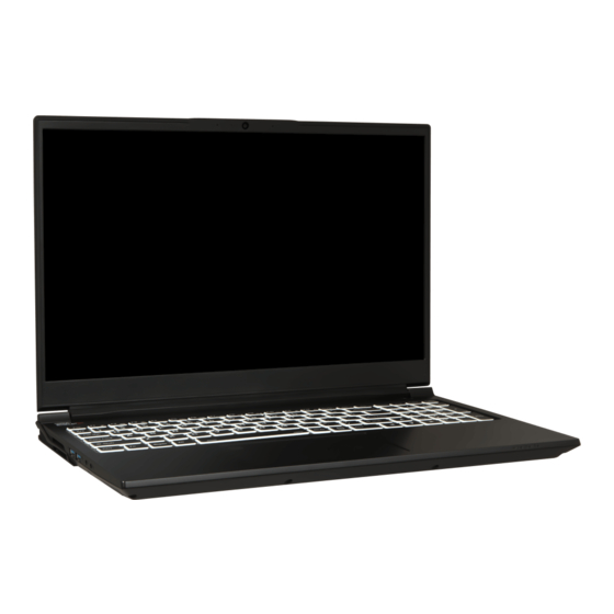
- Page 1 Preface Notebook Computer PD50PNT / PD50PNN / PD50PNR Service Manual...
- Page 2 Preface Notice The company reserves the right to revise this publication or to change its contents without notice. Information contained herein is for reference only and does not constitute a commitment on the part of the manufacturer or any subsequent ven- dor.
- Page 3 This manual is intended for service personnel who have completed sufficient training to undertake the maintenance and inspection of personal computers. It is organized to allow you to look up basic information for servicing and/or upgrading components of the PD50PNT / PD50PNN / PD50PNR series notebook PC.
- Page 4 Preface IMPORTANT SAFETY INSTRUCTIONS Follow basic safety precautions, including those listed below, to reduce the risk of fire, electric shock and injury to per- sons when using any electrical equipment: 1. Do not use this product near water, for example near a bath tub, wash bowl, kitchen sink or laundry tub, in a wet basement or near a swimming pool.
- Page 5 Preface Instructions for Care and Operation The notebook computer is quite rugged, but it can be damaged. To prevent this, follow these suggestions: Don’t drop it, or expose it to shock. If the computer falls, the case and the components could be damaged. Do not expose the computer Do not place it on an unstable Do not place anything heavy...
- Page 6 Preface Avoid interference. Keep the computer away from high capacity transformers, electric motors, and other strong mag- netic fields. These can hinder proper performance and damage your data. Take care when using peripheral devices. Use only approved brands of Unplug the power cord before peripherals.
- Page 7 Preface Battery Precautions • Only use batteries designed for this computer. The wrong battery type may explode, leak or damage the computer. • Do not continue to use a battery that has been dropped, or that appears damaged (e.g. bent or twisted) in any way. Even if the computer continues to work with a damaged battery in place, it may cause circuit damage, which may possibly result in fire.
- Page 8 Preface Related Documents You may also need to consult the following manual for additional information: User’s Manual on CD/DVD This describes the notebook PC’s features and the procedures for operating the computer and its ROM-based setup pro- gram. It also describes the installation and operation of the utility programs provided with the notebook PC. System Startup 1.
-
Page 9: Table Of Contents
Introduction ..........1-1 Bottom ................... A-4 Main Board ................... A-5 Overview ..................1-1 LCD (PD50PNT / PD50PNN / PD50PNR) ........A-6 Specifications ..................1-2 LCD (PD50PNT-D / PD50PNN-D / PD50PNR-D) ...... A-7 External Locator - Top View with LCD Panel Open ......1-4 LCD (PD50PNT-G / PD50PNN-G / PD50PNR-G) ...... A-8 External Locator - Front &... - Page 10 Preface Frame Buffer Partition B .............. B-26 NB Connector ................B-58 Frame Buffer Partition C_D ............B-27 Backlight KB ................B-59 Frame Buffer Partition C .............. B-28 Card Connector ................B-60 Frame Buffer Partition C .............. B-29 5V, 5VS, 3.3V, 3.3VS ..............B-61 Frame Buffer Partition D .............. B-30 VDD3, VDD5 ................B-62 Frame Buffer Partition D ..............
-
Page 11: Introduction
Chapter 1: Introduction Overview This manual covers the information you need to service or upgrade the PD50PNT / PD50PNN / PD50PNR series note- book computer. Information about operating the computer (e.g. getting started, and the Setup utility) is in the User’s Manual. -
Page 12: Specifications
NVIDIA® G-SYNC™Technology only service center for more details. Variable Rate Shading BIOS NVIDIA® Discrete GPU 256Mb SPI Flash ROM NVIDIA® GeForce RTX 3080Ti / GN20-E8 (PD50PNT) INSYDE BIOS 16GB GDDR6 Video RAM Memory Microsoft DirectX®12 Compatible CPU Speed & Computer in DC Mode Dual Channel DDR4 NVIDIA®... - Page 13 Introduction Keyboard Communication Features Full Size Multi Full Color LED Keyboard (with numeric key- Built-In 10/100/1000Mb Base-TX Ethernet LAN Virtual Reality Ready pad) 1.0M HD Webcam Windows® Mixed Reality Compatible Pantone Certificate* (Factory Option) Full Size Full Color “Per Key” LED Key- (Factory Option) 2.0M FHD Webcam NVIDIA G-SYNC Technology at Dynamic Display Switch board (with numeric keypad)
-
Page 14: External Locator - Top View With Lcd Panel Open
Introduction External Locator - Top View with LCD Panel Open Figure 1 Top View 1. Webcam 2. *Camera LED *When the PC camera is in use, the LED will be illuminated. 3. Built-In Array Microphone 4. Display 5. Power Button 6. -
Page 15: External Locator - Front & Right Side Views
Introduction External Locator - Front & Right Side Views Figure 2 Front View 1. LED Indicators FRONT VIEW Figure 3 Right Side View 1. MicroSD Card Reader 2. DisplayPort 1.4 over USB 3.2 RIGHT SIDE VIEW Gen 2 Type-C Port 3. -
Page 16: External Locator - Left Side & Rear View
Introduction External Locator - Left Side & Rear View Figure 4 Left Side View 1. Vent 2. USB 3.2 Gen 1 Type-A Port LEFT SIDE VIEW 3. Powered USB 3.2 Gen 1 Type-A Port 4. 2-In-1 Audio Jack (Headphone and Microphone) 5. -
Page 17: External Locator - Bottom View
Introduction External Locator - Bottom View Figure 6 Bottom View 1. Vent 2. RJ-45 LAN Jack 3. Speakers Overheating To prevent your com- puter from overhea- ting, make sure no- thing blocks any vent while the computer is in use. External Locator - Bottom View 1 - 7... -
Page 18: Mainboard Overview - Top (Key Parts)
Introduction Mainboard Overview - Top (Key Parts) Figure 7 Mainboard Top Key Parts 1 - 8 Mainboard Overview - Top (Key Parts) -
Page 19: Mainboard Overview - Bottom (Key Parts)
Introduction Mainboard Overview - Bottom (Key Parts) Figure 8 Mainboard Bottom Key Parts 1. CPU 2. GPU 3. KBC-ITE IT5570 4. Memory Slots DDR4 SO-DIMM 5. Mini-Card Connector (M.2 PCIE SSD Module) 6. Mini-Card Connector (M.2 PCIE SSD Module) 7. Mini-Card Connector (WLAN Module) Mainboard Overview - Bottom (Key Parts) 1 - 9... -
Page 20: Mainboard Overview - Top (Connectors)
Introduction Mainboard Overview - Top (Connectors) Figure 9 Mainboard Top Connectors 1. Per Key Connector 2. Keyboard Cable Connector 3. Keyboard LED Connector 4. Card Reader 5. Type-C Connector 6. LAN Board Connector 1 - 10 Mainboard Overview - Top (Connectors) -
Page 21: Mainboard Overview - Bottom (Connectors)
Introduction Mainboard Overview - Bottom (Connectors) Figure 10 Mainboard Bottom Connectors 1. DC-In Jack 2. Thunderbolt 4 Port 3. HDMI-Out Port 4. Mini DisplayPort 5. Panel Connector 6. Audio Board Connector 7. Fan Connector 8. Battery Cable Connector 9. RTC Battery Connector Mainboard Overview - Bottom (Connectors) 1 - 11... - Page 22 Introduction 1 - 12...
-
Page 23: Disassembly
LCD to avoid any damage caused by the nature of the structure. Overview This chapter provides step-by-step instructions for disassembling the PD50PNT / PD50PNN / PD50PNR series note- book’s parts and subsystems. When it comes to reassembly, reverse the procedures (unless otherwise indicated). ... -
Page 24: Maintenance Tools
Disassembly NOTE: All disassembly procedures assume that the system is turned OFF, and disconnected from any power supply (the battery is removed too). Maintenance Tools The following tools are recommended when working on the notebook PC: • M3 Philips-head screwdriver •... -
Page 25: Maintenance Precautions
Disassembly Maintenance Precautions The following precautions are a reminder. To avoid personal injury or damage to the computer while performing a re- moval and/or replacement job, take the following precautions: Power Safety Don't drop it. Perform your repairs and/or upgrades on a stable surface. If the computer falls, the case and other components Warning could be damaged. -
Page 26: Disassembly Steps
Disassembly Disassembly Steps The following table lists the disassembly steps, and on which page to find the related information. PLEASE PERFORM THE DISASSEMBLY STEPS IN THE ORDER INDICATED. To remove the Battery: To remove the Hinge Cover: 1. Remove the battery page 2 - 5 1. -
Page 27: Removing The Battery
Disassembly Removing the Battery Figure 1 Battery Removal 1. Turn off the computer, turn it over. 2. Remove screws (Figure 1a). a. Remove the screws. 3. Carefully lift the bottom case up in the direction of the arrow at point (Figure 1b b. - Page 28 Disassembly 6. Carefully disconnect the cable , then remove screws (Figure 2d Figure 2 7. Lift the battery off the computer at point as shown (Figure 2e Battery Removal 8. Reverse the process to install a new battery (do not forget to replace all the screws and bottom cover). (cont’d.) d.
-
Page 29: Removing And Installing The Keyboard
Disassembly Removing and Installing the Keyboard Figure 3 Keyboard Removal Keyboard Removal Procedure a. Remove the adhesive 1. Turn off the computer, remove the battery (page 2 - mylar from the keyboard. 2. The keyboard adhesive mylar will be visible at point on the computer. - Page 30 Disassembly 4. Carefully lift the keyboard up, being careful not to bend the keyboard ribbon cable . Disconnect the key- Figure 4 board ribbon cable from the locking collar socket by using a flat-head screwdriver to pry the locking collar pins Keyboard Removal away from the base (Figure...
- Page 31 Disassembly Keyboard Installation Procedure Figure 5 1. Make sure to insert a part of the adhesive mylar and then install it properly in the location as shown (Figure Keyboard 5a). Installation 2. Pull the mylar cover to reveal the adhesive side of the mylar (Figure 5b).
-
Page 32: Removing And Installing The Heatsink
Disassembly Removing and Installing the Heatsink Figure 6 Heatsink Removal Heatsink Removal Procedure a. Disconnect cable 1. Turn off the computer, remove the battery (page 2 - and remove the screws 2. Disconnect cables and remove screws from the heatsink unit in the order indicated (i.e screw in the correct order. - Page 33 Disassembly 6. Wipe clean the thermal grease residue from the CPU and VGA (Figure 7e). Figure 7 7. Carefully remove the metal pad and any metal pad residue off the CPU (Figure 7f). Make sure that the Heatsink Removal CPU is properly clean of the thermal grease and metal pad. (cont’d.) 8.
- Page 34 Disassembly Heatsink Installation Procedure Figure 8 Heatsink Installation 1. Place the grease mylar pad and then apply the thermal grease as shown (Figure 8a). 2. Remove the grease mylar pad and replace it with VGA mylar pad , make sure to press the VGA mylar pad a.
- Page 35 Disassembly 6. Place the VGA metal pad in the heatsink and CPU metal pad in the mainboard accordingly (Figure 9f). Figure 9 7. Insert the heatsink and tighten the heat sink screws in the order indicated and reconnect the cables Heatsink Installation (Figure 9g).
-
Page 36: Removing The System Memory (Ram)
Disassembly Removing the System Memory (RAM) Figure 10 RAM Module The computer has four memory sockets for 260 pin Small Outline Dual In-line Memory Modules (SO-DIMM) support- Removal ing DDR4 Up to 3200 MHz. The main memory can be expanded up to 64GB. The total memory size is automatically detected by the POST routine once you turn on your computer. -
Page 37: Removing The M.2 Ssd Module
Disassembly Removing the M.2 SSD Module Figure 11 M.2 SSD-1 Module M.2 SSD-1 Removal Procedure Removal 1. Turn off the computer, remove the battery (page 2 - 2. The M.2 SSD modules will be visible at point on the mainboard (Figure 11a). - Page 38 Disassembly M.2 SSD-2 Removal Procedure Figure 12 M.2 SSD-2 Module 1. Turn off the computer, remove the battery (page 2 - Removal 2. The M.2 SSD modules will be visible at point on the mainboard (Figure 12a). 3. Remove the screw (Figure 12b).
-
Page 39: Removing The Wireless Lan Module
Disassembly Removing the Wireless LAN Module Figure 13 Wireless LAN 1. Turn off the computer, remove the battery (page 2 - 5) and SSD-1 (page 2 - 15). Module Removal 2. The Wireless LAN module will be visible at point on the mainboard (Figure 13a). - Page 40 Disassembly Wireless LAN, Combo Module Cables Note that the cables for connecting to the antennae on WLAN, WLAN & Bluetooth Combo modules are not labelled. The cables/covers (each cable will have either a black or transparent cable cover) are color coded for identification as outlined in the table below.
- Page 41 Disassembly Removing the Hinge Cover Figure 14 Hinge Cover 1. Turn off the computer, remove the battery (page 2 - 5) and heatsink. Removal 2. The hinge cover will be visible at point 3. Remove the screw (Figure 14a). a. Remove the screw. 4.
-
Page 42: Lcd (Pd50Pnt / Pd50Pnn / Pd50Pnr
Disassembly Removing the CCD Figure 15 CCD Removal 1. Turn off the computer, turn it over to remove the battery (page 2 - 2. Lay the computer down on a flat surface with the top case up forming a 130 degree angle. a. - Page 43 Disassembly 5. Disconnect the cable from the locking collar socket by using a flat-head screwdriver to pry the locking collar Figure 16 pins away from the base (Figure 16c). CCD Removal 6. Remove the CCD module (Figure 16d). (cont’d) 7. Reverse the process to install a new CCD module. c.