Siemens SITRANS FUS060 Operating Instructions Manual
Ultrasonic flowmeters
Hide thumbs
Also See for SITRANS FUS060:
- Operating instructions manual (52 pages) ,
- Quick start manual (17 pages) ,
- Operating instructions manual (124 pages)
Table of Contents
Advertisement
Quick Links
SITRANS F
Ultrasonic Flowmeters
SITRANS FUS060 with HART
Operating Instructions
7ME305 (FUS060 with HART)
09/2021
A5E01204521-AL
Introduction
Safety notes
Description
Installing/Mounting
Connecting
Commissioning
Functions
Service and maintenance
Diagnostics and
troubleshooting
Technical specifications
Dimension drawings
Product documentation and
support
HART communication
HMI menu structure
1
2
3
4
5
6
7
8
9
10
11
A
B
C
Advertisement
Table of Contents

Related Manuals for Siemens SITRANS FUS060


Summary of Contents for Siemens SITRANS FUS060
- Page 1 Introduction Safety notes Description SITRANS F Installing/Mounting Ultrasonic Flowmeters SITRANS FUS060 with HART Connecting Commissioning Operating Instructions Functions Service and maintenance Diagnostics and troubleshooting Technical specifications Dimension drawings Product documentation and support HART communication HMI menu structure 7ME305 (FUS060 with HART)
- Page 2 Note the following: WARNING Siemens products may only be used for the applications described in the catalog and in the relevant technical documentation. If products and components from other manufacturers are used, these must be recommended or approved by Siemens. Proper transport, storage, installation, assembly, commissioning, operation and maintenance are required to ensure that the products operate safely and without any problems.
-
Page 3: Table Of Contents
Turning the local display..................... 28 Connecting ............................29 Wiring the transducer cables ....................31 Wiring output and power supply ..................33 Commissioning ............................ 37 Start up ..........................37 Operating the device......................37 SITRANS FUS060 with HART Operating Instructions, 09/2021, A5E01204521-AL... - Page 4 Keying in sensor data ......................68 Diagnostics and troubleshooting......................71 Application information guide.................... 73 Technical specifications ........................75 10.1 SITRANS FUS060 ........................ 75 Dimension drawings ..........................81 11.1 Dimensional drawings......................81 Product documentation and support ....................83 Product documentation ..................... 83 Technical support.......................
- Page 5 C.1.4 Menu 4 - Device outputs ....................110 C.1.5 Menu 5 - Identification ..................... 111 C.1.6 Menu 6 - Service ......................112 C.1.7 Menu 7 - Sensor parameters..................... 115 Index ..............................121 SITRANS FUS060 with HART Operating Instructions, 09/2021, A5E01204521-AL...
- Page 6 Table of contents SITRANS FUS060 with HART Operating Instructions, 09/2021, A5E01204521-AL...
-
Page 7: Introduction
For flowmeters based on the FUS060 transmitter various technical literature such as operating instructions and quick start guides are available on the CD-ROM shipped with the device, or it can be found on the Internet at www.siemens.com/flowdocumentation (www.siemens.com/ flowdocumentation), where further information on the SITRANS F flowmeter range is also available. -
Page 8: Designated Use
Using a damaged or incomplete device Risk of explosion in hazardous areas. • Do not use damaged or incomplete devices. Items supplied • SITRANS FUS060 • Wall mounting bracket (standard) • DVD containing certificates • Safety note SITRANS FUS060 with HART Operating Instructions, 09/2021, A5E01204521-AL... -
Page 9: Security Information
Siemens’ products and solutions undergo continuous development to make them more secure. Siemens strongly recommends that product updates are applied as soon as they are available and that the latest product versions are used. Use of product versions that are no longer supported, and failure to apply the latest updates may increase customer’s exposure to cyber... -
Page 10: How To Read The Operating Instructions
The content reflects the technical status at the time of publishing. Siemens reserves the right to make technical changes in the course of further development. - Page 11 Introduction 1.10 Further Information Product information on the internet (http://www.siemens.com/flowdocumentation) Worldwide contact person If you need more information or have particular problems not covered sufficiently by these Operating Instructions, get in touch with your contact person. You can find contact information...
- Page 12 Introduction 1.10 Further Information SITRANS FUS060 with HART Operating Instructions, 09/2021, A5E01204521-AL...
-
Page 13: Safety Notes
Material compatibility Siemens Flow Instruments can provide assistance with the selection of wetted sensor parts. However, the full responsibility for the selection rests with the customer and Siemens Flow Instruments can take no responsibility for any failure due to material incompatibility. -
Page 14: Installation In Hazardous Locations
• PTB 07 ATEX 2033 X with the marking: II 2 G Ex db eb mb [ia Ga] IIC T6…T3 Gb The device's compliance with Essential Health and Safety Requirements has been assured by compliance with: SITRANS FUS060 with HART Operating Instructions, 09/2021, A5E01204521-AL... - Page 15 108 μH 750 mW Digital output 2 (relay) Ex ia IIC/IIB or Ex ib IIC/IIB (Terminals 3+ and 4-) (passive output) 30 V 100 mA (DC), 50 mA (AC) 24 nF 73 μH SITRANS FUS060 with HART Operating Instructions, 09/2021, A5E01204521-AL...
- Page 16 SONO 3000 and SITRANS FUS SONOKIT, which – for their part – are approved only for connection to a transmitter of type series SITRANS FUS060. 2. The connecting cable of the transmitter, type SITRANS FUS060 shall be layed as fixed installation and in such a way that it is sufficiently protected against damage.
- Page 17 < 500 V AC applied between the conductor/ground, conductor/shield and shield/ ground. Connect the devices that are operated in hazardous areas as per the stipulations applicable in the country of operation, e.g. for Ex "d" and "nA", permanent cables must be laid. SITRANS FUS060 with HART Operating Instructions, 09/2021, A5E01204521-AL...
- Page 18 Safety notes 2.3 Installation in hazardous locations SITRANS FUS060 with HART Operating Instructions, 09/2021, A5E01204521-AL...
-
Page 19: Description
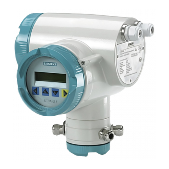
04.00 4.00.00-15 Design SITRANS FUS060 is an ultrasonic flow transmitter engineered for high performance and suitable for use with 1-path, 2-path, and 4-path flow sensors. The complete flowmeter consists of an ultrasonic flow sensor of the types SONO 3100, SONO 3300 or SONOKIT and the associated SITRANS FUS060 transmitter. - Page 20 Description 3.2 Design Figure 3-1 FUS060 SITRANS FUS060 with HART Operating Instructions, 09/2021, A5E01204521-AL...
-
Page 21: Nameplate Layout
Interface for circuits with type of protection intrinsic safety Gas group IIC T6…T3 Temperature class (read manual) Protection level Gb for use in Zone 1 ⑧ Year of Manuf. Year of manufacture Figure 3-2 FUS060 identification nameplate example SITRANS FUS060 with HART Operating Instructions, 09/2021, A5E01204521-AL... -
Page 22: Measuring Principle
The proportional flow factor K is determined by "WET" calibration or calculated by "AUTO" in case of manual programming of mechanical/geometrical pipe data (SONOKIT only). The transducer angle (θ), distance between sensors (L) and pipe dimension (D and D ) are shown in the figure below. SITRANS FUS060 with HART Operating Instructions, 09/2021, A5E01204521-AL... - Page 23 Description 3.4 Measuring principle The ultrasonic signal is sent directly between the transducers. The advantage gained sending signals from point to point is an extremely good signal strength. SITRANS FUS060 with HART Operating Instructions, 09/2021, A5E01204521-AL...
- Page 24 Description 3.4 Measuring principle SITRANS FUS060 with HART Operating Instructions, 09/2021, A5E01204521-AL...
-
Page 25: Installing/Mounting
• Make sure that pressure and temperature specifications indicated on the device nameplate / label will not be exceeded. WARNING Installation in hazardous location Special requirements apply to the location and interconnection of sensor and transmitter. See Installation in hazardous locations (Page 14) SITRANS FUS060 with HART Operating Instructions, 09/2021, A5E01204521-AL... -
Page 26: Transmitter Installation
The standard wall-mounting bracket is only suitable for wall mounting. 4.2.2 Pipe or wall mounting with assembly bracket Note The special wall-mounting bracket is not part of the standard delivery and must be ordered separately. SITRANS FUS060 with HART Operating Instructions, 09/2021, A5E01204521-AL... - Page 27 1. Fasten the assembly bracket to the back of the transmitter 2. Fasten the transmitter and assembly bracket to the wall Note The fastening brackets and nuts are not needed for wall mounting. Wall mounting with assembly bracket. Dimensions in mm (inch). SITRANS FUS060 with HART Operating Instructions, 09/2021, A5E01204521-AL...
-
Page 28: Turning The Local Display
5. Pull out the unit, turn it to the desired position and push it back in. 6. Screw the lid back on and mount the lid catch. ① Fastening hooks Figure 4-2 Unlocking the fastening hooks on the local display SITRANS FUS060 with HART Operating Instructions, 09/2021, A5E01204521-AL... -
Page 29: Connecting
Power supply entry ⑥ Terminal box lid for transducer / sensor cables Figure 5-1 Overview, Electrical connections Safety measurements WARNING Qualified personnel Only qualified personnel may carry out work on the electrical connections. SITRANS FUS060 with HART Operating Instructions, 09/2021, A5E01204521-AL... - Page 30 • Earth transmitter housing on the PE connector. • Cables used for connection must have diameters fitting the glands. • Use shielded cables for the outputs. • Compare data on rating plate with local power supply. SITRANS FUS060 with HART Operating Instructions, 09/2021, A5E01204521-AL...
-
Page 31: Wiring The Transducer Cables
3. Carefully press the cables into the cable glands until the "snap" function fixes the cable inside the connection module. Make sure the cables are mounted correctly by smoothly pulling the cable. SITRANS FUS060 with HART Operating Instructions, 09/2021, A5E01204521-AL... - Page 32 7. After the installation, check and, if necessary, correct the cable length setting of the transmitter (see menu 7). Wiring 1-path systems ① For 1-path sensors exchange the two unused cable glands with the blind plugs. Figure 5-2 Wiring transducer cables, 1-path system. SITRANS FUS060 with HART Operating Instructions, 09/2021, A5E01204521-AL...
-
Page 33: Wiring Output And Power Supply
1. Release the lid of the terminal box by turning the 3 mm hexagon socket screw. 2. Unscrew the lid. 3. Push the power cable and signal cable through the cable glands up to the terminal block. SITRANS FUS060 with HART Operating Instructions, 09/2021, A5E01204521-AL... - Page 34 8. Tighten the cable glands and check strain relief. 9. Lay cables in a bend in front of the cable glands to prevent moisture getting into terminal block. 10.Replace unused cable glands with certified blanking plugs. SITRANS FUS060 with HART Operating Instructions, 09/2021, A5E01204521-AL...
- Page 35 Connecting 5.2 Wiring output and power supply 11.Screw the lid tightly on to the housing by using a tool. The sealing ring must be clean and undamaged. 12.Remount the lid lock. SITRANS FUS060 with HART Operating Instructions, 09/2021, A5E01204521-AL...
- Page 36 Connecting 5.2 Wiring output and power supply SITRANS FUS060 with HART Operating Instructions, 09/2021, A5E01204521-AL...
-
Page 37: Commissioning
Error symptoms (Page 71). The failure signal is output at the output. Operating the device The device can be operated in the following ways: • Local display (LUI) • HART • SIMATIC PDM (PC/laptop) SITRANS FUS060 with HART Operating Instructions, 09/2021, A5E01204521-AL... -
Page 38: Commissioning Via Local User Interface
The device can be operated using a HART communicator or a HART-based controlling system. Electrical connection of the PC/laptop with HART modem and HART communicator to the 4 to 20 mA signal line is shown in figure below. SITRANS FUS060 with HART Operating Instructions, 09/2021, A5E01204521-AL... -
Page 39: Navigating The Menu
• Enter device function or setting level of parameters with the key (Enter function). • Exit the selected function or setting level without storage of the change by using the until the cursor key moves to the far left position. SITRANS FUS060 with HART Operating Instructions, 09/2021, A5E01204521-AL... -
Page 40: Write Protection
• About 10 minutes after actuating the last optical keypad • After entering any number, not the personal code, in menu 6.1 Enter code Note The programming is permanently enabled with code = 0 (factory setting). SITRANS FUS060 with HART Operating Instructions, 09/2021, A5E01204521-AL... -
Page 41: Operating Examples
The optical keypads to be actuated are specified and the individual operating steps numbered consecutively. Example 1 - Setting of menu language Starting point is the multi-display Figure 6-3 Changing language from factory-set "English" to "German (Deutsch)" SITRANS FUS060 with HART Operating Instructions, 09/2021, A5E01204521-AL... - Page 42 Commissioning 6.3 Commissioning via local user interface Example 2 - Changing the display flow unit Figure 6-4 Changing the flow value unit from m /h to ft SITRANS FUS060 with HART Operating Instructions, 09/2021, A5E01204521-AL...
-
Page 43: Commissioning Via Simatic Pdm
Starting point is the sub-menu 4.2.3 (Pulse value) Commissioning via SIMATIC PDM SIMATIC PDM (Process Device Manager) is a software package for configuring, parameterizing, commissioning, and maintaining field devices (for example transducers). SITRANS FUS060 with HART Operating Instructions, 09/2021, A5E01204521-AL... -
Page 44: Configuration
Some special characters are not supported via the SIMATIC PDM communication. In case of uploading such into the FUS060 a "?" is displayed instead. A "Ü" is changed to "ü" in the device display. SITRANS FUS060 with HART Operating Instructions, 09/2021, A5E01204521-AL... - Page 45 2. Installing the device driver (download from EDD download (http:// support.automation.siemens.com/WW/view/en/24481552/133100)). 3. Adding the device to the SIMATIC PDM network. 4. Configuring the device. 5. Optimizing the system. 6. Checking the operation readiness. SITRANS FUS060 with HART Operating Instructions, 09/2021, A5E01204521-AL...
- Page 46 Commissioning 6.4 Commissioning via SIMATIC PDM SITRANS FUS060 with HART Operating Instructions, 09/2021, A5E01204521-AL...
-
Page 47: Functions
Set the backlight turn-off. At power-off this function is automatically reset to the default value Off. Off: At infrared key operation, the light turns on automatically and off again 10 minutes after last key action. SITRANS FUS060 with HART Operating Instructions, 09/2021, A5E01204521-AL... - Page 48 Frequency and Current output (menus 1.7 and 1.8) The arithmetically calculated output values are displayed in the menu 1.7 Frequency (in Hz) and in menu 1.8 Current Output (in mA), irrespective of whether the output is used. SITRANS FUS060 with HART Operating Instructions, 09/2021, A5E01204521-AL...
-
Page 49: Diagnostics (Menu 2)
After every reset or power off of the device, all error messages are available again, thus this menu setting is not stored. Device test (menu 2.3) The following test sub routines are available: SITRANS FUS060 with HART Operating Instructions, 09/2021, A5E01204521-AL... -
Page 50: Measuring Functions (Menu 3)
• Limits (Lo alarm limit, Hi alarm limit and Hysteresis) • Time constant (damping) Note When switching between different units a rounding-off may need to be corrected manually. Density (menu 3.1.4) After entering units the display will automatically step into Density. SITRANS FUS060 with HART Operating Instructions, 09/2021, A5E01204521-AL... - Page 51 % of full scale value. If, for example, the hysteresis is 1% (default), the relay contact does not switch until flow is –1% of full scale value and it returns to its original position when flow is +1% of full scale value. SITRANS FUS060 with HART Operating Instructions, 09/2021, A5E01204521-AL...
- Page 52 If individual totalizers are not reset or started at the same time, the reading on the net totalizer may deviate from the difference between the forward and reverse totalizer values. SITRANS FUS060 with HART Operating Instructions, 09/2021, A5E01204521-AL...
-
Page 53: Device Outputs (Menu 4)
Digital outp 1 (menu 4.2) (Terminals 5+ and 6-) In this menu the output function (pulse, frequency or alarm/limits) is assigned and the signal type as well as the pulse/frequency parameters are set. SITRANS FUS060 with HART Operating Instructions, 09/2021, A5E01204521-AL... - Page 54 ("P/F too high") will appear. If the pulse/frequency error message appears, it is required to adjust the pulse settings (menus 4.2.3 and 4.2.4) or the full scale frequency (menu 4.2.5). SITRANS FUS060 with HART Operating Instructions, 09/2021, A5E01204521-AL...
- Page 55 Passive ③ Counter ④ External supply Figure 7-2 Active and passive signals Signals with positive and negative logic can be generated (positive or negative pulses). The figure below illustrates the setting options. SITRANS FUS060 with HART Operating Instructions, 09/2021, A5E01204521-AL...
- Page 56 The frequency is permanently assigned to the flow. The pulse/pause ratio is constant 1:1. If the "Frequency" function is selected, the "Full scale frq" is set in the range from 2 to 10 000 Hz. Digital outp 2 (menu 4.3) (Terminals 3+ and 4-) SITRANS FUS060 with HART Operating Instructions, 09/2021, A5E01204521-AL...
- Page 57 The electronic fuse is tripped in the event of overloading. The recovery time of the fuse is a few minutes. The relay contact is open in the no-load state. SITRANS FUS060 with HART Operating Instructions, 09/2021, A5E01204521-AL...
-
Page 58: Identification (Menu 5)
(finger continuously touching the glass panel), the characters are automatically scrolled. Manuf. Ident. (menu 5.2) The product-specific identification data can be read in the following submenus: • Product type (menu 5.2.1) • Serial number (menu 5.2.2) SITRANS FUS060 with HART Operating Instructions, 09/2021, A5E01204521-AL... -
Page 59: Service (Menu 6)
The four-digit personal code number can be created in this menu. The local write protection is activated for values > 0, that is menus can still be accessed but parameters cannot be changed. SITRANS FUS060 with HART Operating Instructions, 09/2021, A5E01204521-AL... - Page 60 Unused paths will show 0. Normal values are in the range of 40 to 100. High gain values refer to a high sound absorption in the medium (maximum 255 for no sonic transfer, for example by empty pipe or if no sensor cable is connected). SITRANS FUS060 with HART Operating Instructions, 09/2021, A5E01204521-AL...
-
Page 61: Sensor Parameters (Menu 7)
Flowmeter systems with SONO 3100 or SONO 3300 All sensor characteristics in menu 7 are determined and preset at the factory. They should not be changed for flowmeter systems with sensor types SONO 3100 and SONO 3300. SITRANS FUS060 with HART Operating Instructions, 09/2021, A5E01204521-AL... - Page 62 7.1.4.x.6 show the automatically calculated calibration factor). Always use WET calibration mode for flowmeter systems with SONO 3100 or SONO 3300 sensors (menus 7.1.4.x.6 show the calibration factor, and menus 7.1.4.x.7 show the calculated flow). SITRANS FUS060 with HART Operating Instructions, 09/2021, A5E01204521-AL...
- Page 63 Roughness (menu 7.1.3.2) Roughness is the value for the inner pipe surface and should only be changed for SONOKIT. The range of this value is 0.01 mm to 10.0 mm. The standard Siemens sensors have a roughness of approximately 0.4 mm.
- Page 64 In this menu the displacement for each path (h in the figure above) can be read and should only be changed for SONOKIT. "h" is the distance between the path and the center of the pipe. Data for SONOKIT to be entered from the SONOKIT sensor geometry measurement report. SITRANS FUS060 with HART Operating Instructions, 09/2021, A5E01204521-AL...
- Page 65 In this menu the number of paths is set depending on the sensor design. The number of paths is preset from factory and can be changed to 1-path, 2-path, 3-path or 4-path. The number of paths should only be changed for SONOKIT. SITRANS FUS060 with HART Operating Instructions, 09/2021, A5E01204521-AL...
- Page 66 Functions 7.7 Sensor parameters (menu 7) SITRANS FUS060 with HART Operating Instructions, 09/2021, A5E01204521-AL...
-
Page 67: Service And Maintenance
To return a product to Siemens, see AUTOHOTSPOT. Contact your Siemens representative to clarify if a product is repairable, and how to return it. They can also help with quick repair processing, a repair cost estimate, or a repair report/cause of failure report. -
Page 68: Keying In Sensor Data
8. Enter the measured angle for each path (menus 7.1.4.x.2). 9. Enter the measured displacement for each path (menu 7.1.4.x.3). Enter 0 for paths not used. 10.Check the number of paths (menu 7.2). They are preset from factory according to order. SITRANS FUS060 with HART Operating Instructions, 09/2021, A5E01204521-AL... - Page 69 Based on the entered data the transmitter is capable of measuring and calculating the actual flow. The accuracy of the system at this stage is dependent on for example the entered accuracy of the geometry data. SITRANS FUS060 with HART Operating Instructions, 09/2021, A5E01204521-AL...
- Page 70 Service and maintenance 8.3 Keying in sensor data SITRANS FUS060 with HART Operating Instructions, 09/2021, A5E01204521-AL...
-
Page 71: Diagnostics And Troubleshooting
• Error counters (me‐ turbance is present. nus 6.5.4.X) are not equal to 0. SITRANS FUS060 with HART Operating Instructions, 09/2021, A5E01204521-AL... - Page 72 Operation with infrared keys not Light interference Check that display is not dirty. possible Check that display lid is locked (PDM force control). Bright auxiliary tools may be of assis‐ tance. SITRANS FUS060 with HART Operating Instructions, 09/2021, A5E01204521-AL...
-
Page 73: Application Information Guide
Explosion protection Table 9-3 Device data Serial number Menu 5.2.2 Product type, Order number Menu 5.2.1 Software version Menu 5.2.3 Device status, error message, frequen‐ Menu 2.1 cy, ... Flow Menu 1.2 SITRANS FUS060 with HART Operating Instructions, 09/2021, A5E01204521-AL... - Page 74 Menu 6.5.3 Error count % Menu 6.5.4 Time of flight up (TOF up) Menu 6.5.5 [ns] Time of flight down (TOF down) Menu 6.5.6 [ns] Delta TOF Menu 6.5.7 [ns] Amplitude Menu 6.5.2 SITRANS FUS060 with HART Operating Instructions, 09/2021, A5E01204521-AL...
-
Page 75: Technical Specifications
Output function, configura‐ Pulse output ble for: Adjustable pulse significance ≤ 5000 pulses/s Adjustable pulse width ≥ 0.1 ms Frequency output selectable up to 10 kHz Function Pulse, frequency, limits, device status, flow direction SITRANS FUS060 with HART Operating Instructions, 09/2021, A5E01204521-AL... - Page 76 ≤ ±0.25% of measured value at 0.5 to 9 m/s Reference conditions (water) Process temperature in the 25 °C ±5 °C (77 °F ±9 °F) connected sensor Ambient temperature at the 25 °C ±5 °C (77 °F ±9 °F) transmitter SITRANS FUS060 with HART Operating Instructions, 09/2021, A5E01204521-AL...
- Page 77 Stainless steel (standard: always incl.) special) Weight 4.4 kg (9.7 lb) Cable glands Power supply and outputs: 2 x M20 or 2 x ½" NPT Transducers/sensor: 2/4 x M16 or 2/4 x ½" NPT SITRANS FUS060 with HART Operating Instructions, 09/2021, A5E01204521-AL...
- Page 78 M25 cable gland set for the FUS060 PA (M25) power and output connection, gray PA plastic, 2 pcs. Order number 085U3332 Cable cross section 9 … 16 mm (0.35" … 0.63") Ambient temperature -40 … +100 °C (-40 … +212 °F) Nominal torque 4 Nm SITRANS FUS060 with HART Operating Instructions, 09/2021, A5E01204521-AL...
- Page 79 -20 … +100 °C (-4 … +212 °F) Nominal torque 3.5 Nm Table 10-9 Certificates and approvals Certificates and approvals Explosion protection ATEX II 2G Ex db eb mb [ia Ga] IIC T6…T3 Gb SITRANS FUS060 with HART Operating Instructions, 09/2021, A5E01204521-AL...
- Page 80 Technical specifications 10.1 SITRANS FUS060 SITRANS FUS060 with HART Operating Instructions, 09/2021, A5E01204521-AL...
-
Page 81: Dimension Drawings
Dimension drawings 11.1 Dimensional drawings Figure 11-1 FUS060 with standard mounting bracket. Figure 11-2 FUS060 with the optional special mounting bracket. SITRANS FUS060 with HART Operating Instructions, 09/2021, A5E01204521-AL... - Page 82 Dimension drawings 11.1 Dimensional drawings SITRANS FUS060 with HART Operating Instructions, 09/2021, A5E01204521-AL...
-
Page 83: Product Documentation And Support
– "Download as html5, only PC": Open or save the manual in the HTML5 view on your PC You can also find manuals with the Mobile app at Industry Online Support (https:// support.industry.siemens.com/cs/ww/en/sc/2067). Download the app to your mobile device and scan the device QR code. Product documentation by serial number Using the PIA Life Cycle Portal, you can access the serial number-specific product information including technical specifications, spare parts, calibration data, or factory certificates. -
Page 84: Technical Support
Additional information on our technical support can be found at Technical Support (http:// www.siemens.com/automation/csi/service). Service & support on the Internet In addition to our technical support, Siemens offers comprehensive online services at Service & Support (http://www.siemens.com/automation/service&support). Contact If you have further questions about the device, contact your local Siemens representative at Personal Contact (http://www.automation.siemens.com/partner). -
Page 85: Hart Communication
Write Read Unique Identifier Associated With 254, Read manufacturer_id, device_type, request_preambles, universal_revision, transmitter_revision, software_revision, hardware_revision <0xf8>, physical_signaling_code <0x07>, device_flags, device_id Read Message message Read Read Tag, Descriptor, Date tag, Read descriptor, date SITRANS FUS060 with HART Operating Instructions, 09/2021, A5E01204521-AL... -
Page 86: Common Practice Commands
Command Perform Device Reset Command Set Primary Variable Zero Command Write Primary Variable Units PV.DIGITAL_UNITS Write Trim Primary Variable Current DAC PV.ANALOG_VALUE Command Zero Trim Primary Variable Current DAC PV.ANALOG_VALUE Command Gain SITRANS FUS060 with HART Operating Instructions, 09/2021, A5E01204521-AL... - Page 87 DEX), transmitter_variables[transmit‐ ter_variable_code].DIGITAL_UNITS Write Number Of Response Preambles response_preambles Write Write Burst Command Number burst_command_number Write Burst Mode Control burst_mode_select Write Read All Dynamic Variables PV.DIGITAL_UNITS, Read PV.DIGITAL_VALUE, SV.DIGITAL_UNITS, SV.DIGITAL_VALUE, TV.DIGITAL_UNITS, TV.DIGITAL_VALUE SITRANS FUS060 with HART Operating Instructions, 09/2021, A5E01204521-AL...
-
Page 88: Device-Specific Commands
Command Read HART Simulation trans1_sim_flow_value Read trans1_sim_flow_mode Write HART Simulation trans1_sim_flow_value, Write trans1_sim_flow_mode Execute HART Test 3 Conmnand Write HART Phys Dout1 Test phys_dout1_test Write Write HART Phys Dout2 Test phys_dout2_test Write SITRANS FUS060 with HART Operating Instructions, 09/2021, A5E01204521-AL... - Page 89 Read HART Analog Parameters func1_AI_flow_hart_ana‐ Read log_alarm_select, func1_AI_flow_hart_upper_ana‐ log_limit Write HART Analog Parameters func1_AI_flow_hart_ana‐ Write log_alarm_select, func1_AI_flow_hart_upper_ana‐ log_limit Read HART Dout1 Parameters phys_dout1_select, Read phys_hart_dout1_mode, phys_dout1_pulse_width, phys_dout1_pulse_valency, phys_pulse_valency_hart_unit, phys_dout1_upper_frequency, phys_dout1_frequency_val SITRANS FUS060 with HART Operating Instructions, 09/2021, A5E01204521-AL...
- Page 90 Write func1_AI_lo_lo_lim, func1_AI_hart_alarm_hys Read HART Func2 Limits func2_AI_hi_hi_lim, Read func2_AI_lo_lo_lim, func2_AI_hart_alarm_hys Write HART Func2 Limits func2_AI_hi_hi_lim, Write func2_AI_lo_lo_lim, func2_AI_hart_alarm_hys Read HART Display Parameters phys_hart_display1_select, Read phys_hart_display2_select, phys_flow_local_display, phys_language_local_display, phys_background_ilum_local_dis‐ play, status_display SITRANS FUS060 with HART Operating Instructions, 09/2021, A5E01204521-AL...
- Page 91 Write HART Range Values func1_AI_pv_upper_range_value, Write func2_AI_pv_upper_range_value, func5_AI_pv_upper_range_value, func1_AI_pv_lower_range_value, func2_AI_pv_lower_range_value, func5_AI_pv_lower_range_value Read HART Damping Values func1_AI_pv_ftime, Read func2_AI_pv_ftime, func5_AI_pv_ftime Write HART Damping Values func1_AI_pv_ftime, Write func2_AI_pv_ftime, func5_AI_pv_ftime SITRANS FUS060 with HART Operating Instructions, 09/2021, A5E01204521-AL...
- Page 92 Write HART Trigger Constants Up phys_trig_const1_1_up, Write phys_trig_const1_2_up, phys_trig_const1_3_up, phys_trig_const1_4_up Read HART Trigger Constants Down phys_trig_const1_1_dw, Read phys_trig_const1_2_dw, phys_trig_const1_3_dw, phys_trig_const1_4_dw Write HART Trigger Constants Down phys_trig_const1_1_dw, Write phys_trig_const1_2_dw, phys_trig_const1_3_dw, phys_trig_const1_4_dw SITRANS FUS060 with HART Operating Instructions, 09/2021, A5E01204521-AL...
- Page 93 Read HART Track3 Layout sensor_track3_length, Read sensor_track3_angle, sensor_track3_displacement Write HART Track3 Layout sensor_track3_length, Write sensor_track3_angle, sensor_track3_displacement Read HART Track4 Layout sensor_track4_length, Read sensor_track4_angle, sensor_track4_displacement Write HART Track4 Layout sensor_track4_length, Write sensor_track4_angle, sensor_track4_displacement SITRANS FUS060 with HART Operating Instructions, 09/2021, A5E01204521-AL...
- Page 94 Read HART Debug Values Track4 phys_debug_gain_up_4, Read phys_debug_gain_dw_4, phys_debug_level_up_4, phys_debug_level_dw_4, phys_debug_trigger_up_4, phys_debug_trigger_dw_4, phys_debug_rm_tdc_tof_up_4, phys_de‐ bug_rm_tdc_tof_down_4, phys_debug_delta_tof_4, phys_debug_meas_error_per‐ cent_4 Read HART Zero Points trans1_zero_TDC_RLZD_1, Read trans1_zero_TDC_RLZD_2, trans1_zero_TDC_RLZD_3, trans1_zero_TDC_RLZD_4 SITRANS FUS060 with HART Operating Instructions, 09/2021, A5E01204521-AL...
- Page 95 Write Write HART Trigger Setting phys_trig_control Write Read HART Software Parameters ShotShotWaitTimeT1, Read ShotShotWaitTimeT2, ShotShotWaitTimeT3, ShotShotWaitTimeT4, ShotPairLoop2CountT1, ShotPairLoop2CountT2, ShotPairLoop2CountT3, ShotPairLoop2CountT4, ShotPairWaitTimeT1, ShotPairWaitTimeT2, ShotPairWaitTimeT3, ShotPairWaitTimeT4, LoopCount3Normal, LoopWaitTime3N, AfterLoopWait3N, LoopCount3Reverse, LoopWaitTime3R, AfterLoopWait3R, LoopCount4, TxGainUpDownCombined SITRANS FUS060 with HART Operating Instructions, 09/2021, A5E01204521-AL...
- Page 96 DAC_4, Read DAC_12, DAC_20 Write HART Analog Output Trim DAC_4, Write DAC_12, DAC_20 Read HART Eeprom Setting usd_eeprom_version, Read eeprom_reset Write HART Eeprom Version usd_eeprom_version Write Write HART Eeprom Reset eeprom_reset Write SITRANS FUS060 with HART Operating Instructions, 09/2021, A5E01204521-AL...
- Page 97 Read HART Trigger Constants 1 phys_trig_const_1, Read phys_trig_const_2, phys_trig_const_3, phys_trig_const_4, phys_trig_const_5, phys_trig_const_6, phys_trig_const_7, phys_trig_const_8, phys_trig_const_9, phys_trig_const_10, phys_trig_const_11, phys_trig_const_12, phys_trig_const_13, phys_trig_const_14, phys_trig_const_15, phys_trig_const_16, phys_trig_const_17, phys_trig_const_18, phys_trig_const_19, phys_trig_const_20, phys_trig_const_21, phys_trig_const_22, phys_trig_const_23, phys_trig_const_24, phys_trig_const_25 SITRANS FUS060 with HART Operating Instructions, 09/2021, A5E01204521-AL...
- Page 98 Read HART Trigger Constants 3 phys_trig_const_51, Read phys_trig_const_52, phys_trig_const_53, phys_trig_const_54, phys_trig_const_55, phys_trig_const_56, phys_trig_const_57, phys_trig_const_58, phys_trig_const_59, phys_trig_const_60, phys_trig_const_61, phys_trig_const_62, phys_trig_const_63, phys_trig_const_64, phys_trig_const_65, phys_trig_const_66, phys_trig_const_67, phys_trig_const_68, phys_trig_const_69, phys_trig_const_70, phys_trig_const_71, phys_trig_const_72, phys_trig_const_73, phys_trig_const_74, phys_trig_const_75 SITRANS FUS060 with HART Operating Instructions, 09/2021, A5E01204521-AL...
- Page 99 Read HART Trigger Constants 5 phys_trig_const_101, Read hys_trig_const_102, phys_trig_const_103, phys_trig_const_104, phys_trig_const_105, phys_trig_const_106, phys_trig_const_107, phys_trig_const_108, phys_trig_const_109, phys_trig_const_110, phys_trig_const_111, phys_trig_const_112, phys_trig_const_113, phys_trig_const_114, phys_trig_const_115, phys_trig_const_116, phys_trig_const_117, phys_trig_const_118, phys_trig_const_119, phys_trig_const_120, phys_trig_const_121, phys_trig_const_122, phys_trig_const_123, phys_trig_const_124, phys_trig_const_125 SITRANS FUS060 with HART Operating Instructions, 09/2021, A5E01204521-AL...
- Page 100 Read HART Trigger Constants 7 phys_trig_const_151, Read phys_trig_const_152, phys_trig_const_153, phys_trig_const_154, phys_trig_const_155, phys_trig_const_156, phys_trig_const_157, phys_trig_const_158, phys_trig_const_159, phys_trig_const_160, phys_trig_const_161, phys_trig_const_162, phys_trig_const_163, phys_trig_const_164, phys_trig_const_165, phys_trig_const_166, phys_trig_const_167, phys_trig_const_168, phys_trig_const_169, phys_trig_const_170, phys_trig_const_171, phys_trig_const_172, phys_trig_const_173, phys_trig_const_174, phys_trig_const_175 SITRANS FUS060 with HART Operating Instructions, 09/2021, A5E01204521-AL...
- Page 101 Write HART Trans1 Flow Tube Diameter trans1_flow_tube_diameter Write Read HART Software Control SWT_TrackNr, Read SWT_StateCnt_1up, SWT_StateCnt_1dw, SWT_StatusUp, SWT_StatusDw, SWT_Status, SWT_GoodCnt, SWT_BadCnt Write HART Software Control SWT_TrackNr Write Read Log List not used Read SITRANS FUS060 with HART Operating Instructions, 09/2021, A5E01204521-AL...
- Page 102 HART communication B.3 Device-specific commands SITRANS FUS060 with HART Operating Instructions, 09/2021, A5E01204521-AL...
-
Page 103: Hmi Menu Structure
HMI menu structure The graphic below only shows the main levels of the menu structure. Figure C-1 Menu structure (main menus; FW 4.00.00-15) SITRANS FUS060 with HART Operating Instructions, 09/2021, A5E01204521-AL... -
Page 104: Menu Items (Fw Rev. 4.00.00-15)
Sound velocity US-Amplitude Analog Output Frequency 1.1.3 Line 2 Parameter value in line 2 Total. net Flow Write Totalizer net Total. forward Total. reverse Flow Velocity Sound velocity US-Amplitude Analog output Frequency SITRANS FUS060 with HART Operating Instructions, 09/2021, A5E01204521-AL... - Page 105 (reference water). Frequency Frequency Display of actual frequency output See menu 4.2.5 Read value (Hz) Current Output Current Output Display of actual current value of an‐ See menu 4.1 Read alogue output (mA) SITRANS FUS060 with HART Operating Instructions, 09/2021, A5E01204521-AL...
-
Page 106: Menu 2 - Diagnostics
Simulation of output signal for digi‐ End (no simulation) Write tal output 1 with selected value 0.1 Hz 1 Hz 10 Hz 100 Hz 1 kHz 10 kHz Alarm on Alarm off SITRANS FUS060 with HART Operating Instructions, 09/2021, A5E01204521-AL... -
Page 107: Menu 3 - Measuring Functions
Upper alarm limit (< Lo alarm limit) Depends on sensor See dimension table Write size in sensor manual 3.1.3.3 Hysteresis Hysteresis for limit in % of full scale 0 % to 20 % Write value SITRANS FUS060 with HART Operating Instructions, 09/2021, A5E01204521-AL... - Page 108 Lower alarm limit (< Hi alarm limit) 1 % to 150 % Write 3.3.2.2 Hi alarm limit Upper alarm limit (> Lo alarm limit) 120 % 1 % to 150 % Write SITRANS FUS060 with HART Operating Instructions, 09/2021, A5E01204521-AL...
- Page 109 Upper alarm limit (> Lo alarm limit) 3.6.4 Hysteresis Hysteresis for the limits 0 to 3 Write 3.6.5 Settings net Volume totalizer reset to “0” and No action No action Write “stop/start” Reset+Stop Reset+Start SITRANS FUS060 with HART Operating Instructions, 09/2021, A5E01204521-AL...
-
Page 110: Menu 4 - Device Outputs
Total. forw. max Total. rev. min Total. net. min Total. net max No function 4.2.2 Signal type Configure output: Passive-pos Active-pos Write Signal: active or passive Active-neg Logic: positive or negative Passive-pos Passive-neg SITRANS FUS060 with HART Operating Instructions, 09/2021, A5E01204521-AL... -
Page 111: Menu 5 - Identification
TAG number on metering unit Max. 8 characters Write 5.1.2 Description TAG number description Max. 16 characters Write 5.1.3 Message Message TAG Max. 32 characters Write Manuf. Ident. 5.2.1 Product type Product type Order number Read SITRANS FUS060 with HART Operating Instructions, 09/2021, A5E01204521-AL... -
Page 112: Menu 6 - Service
0 or 1000 to 9999 Write Code 0: User parameter are not pro‐ tected. Code > 0: User parameters are pro‐ tected. Service code Only for service in the Siemens facto‐ Write Reset Re-start of device without change of Cancel Cancel Write... - Page 113 Trigger level of fourth path up Read 0 - 128; typical: 40 – 100 6.5.3.8 Trig dw 4 Trigger level of fourth path down Read 0 - 128; typical: 40 – 100 6.5.4 Error count % SITRANS FUS060 with HART Operating Instructions, 09/2021, A5E01204521-AL...
- Page 114 +50.000 ns ple +0.000 ns 6.6.1.2 Zr.Pt.Offset 2 Zero offset (ns) of second path Depends on factory -50.000 ns to Write calibration, for exam‐ +50.000 ns ple +0.000 ns SITRANS FUS060 with HART Operating Instructions, 09/2021, A5E01204521-AL...
-
Page 115: Menu 7 - Sensor Parameters
"0" in the display and the output signal to the error signal level C.1.7 Menu 7 - Sensor parameters Note Large sizes With nominal diameter settings above DN 2000 the deivce may not work properly. SITRANS FUS060 with HART Operating Instructions, 09/2021, A5E01204521-AL... - Page 116 1, see Sensor parameters (menu 7) (Page 61). 7.1.4.1. Angle 1 Angle of path 1 Depending of sensor 0 to 89° Write size selected at order‐ SITRANS FUS060 with HART Operating Instructions, 09/2021, A5E01204521-AL...
- Page 117 2, see Sensor parameters (menu 7) (Page 61). 7.1.4.2. Angle 2 Angle of path 2 Depending of sensor 0 to 89° Write size selected at order‐ SITRANS FUS060 with HART Operating Instructions, 09/2021, A5E01204521-AL...
- Page 118 3, see Sensor parameters (menu 7) (Page 61). 7.1.4.3. Angle 3 Angle of path 3 Depending of sensor 0 to 89° Write size selected at order‐ SITRANS FUS060 with HART Operating Instructions, 09/2021, A5E01204521-AL...
- Page 119 Displacement of path 4 (m) Depending of sensor 0 to 1.5 m Write Note: The value must be smaller than size selected at order‐ the half entered pipe diameter (see menu 7.1.3.2.2). SITRANS FUS060 with HART Operating Instructions, 09/2021, A5E01204521-AL...
- Page 120 Number of paths connected to the Depending on or‐ 1-track Write transmitter; dered system config‐ 2-tracks typical 1-track (SONO 3100, SONO‐ uration 3-tracks KIT-1) or 4-tracks 2-tracks (SONO 3100, SONO 3300, SONOKIT-2) SITRANS FUS060 with HART Operating Instructions, 09/2021, A5E01204521-AL...
-
Page 121: Index
Hazardous area Scope of delivery, 8 Approvals, 14 Service, 84 Safety requirements, 16 Application information, 73 History, 7 Service and support Hotline, (Refer to Support request) Internet, 84 Support, 84 Support request, 84 SITRANS FUS060 with HART Operating Instructions, 09/2021, A5E01204521-AL... - Page 122 Index Technical support, 84 partner, 84 personal contact, 84 Temperature specifications, 16 Transit time, 22 Warranty, 10 Wiring, (See Electrical connection) SITRANS FUS060 with HART Operating Instructions, 09/2021, A5E01204521-AL...