Table of Contents
Advertisement
Quick Links
Download this manual
See also:
Installation Manual
Advertisement
Table of Contents

Related Manuals for MSI MPC 400


Summary of Contents for MSI MPC 400
- Page 1 MPC 400 maximize your Digital World User’ s Guide Version 1.0...
- Page 2 Shielded interface cables and AC. power cord, if any, must be used in order to comply with the emission limits. VOIR LA NOTICE D’ INSTALLATION AVANT DE RACCORDER AU RESEAU. Assembled from tested components Complete system not tested Micro-Star International MPC 400...
- Page 3 Lithium Battery Statement CAUTION Danger of explosion if battery is incorrectly replaced. Replace only with the same or equivalent type recommended by the manufacturer. Discard used bat- teries according to the manufacturer’ s instructions. Macrovision Statement ® This product incorporates copyright protection technology that is protected by method claims of certain U.S.
- Page 4 Safety Instructions Always read the safety instructions carefully. Keep this User’ s Manual for future reference. Keep this equipment away from humidity. Lay this equipment on a reliable flat surface before setting it up. The openings on the enclosure are for air convection hence protects the equipment from overheating.
- Page 5 Trademarks All trademarks are the properties of their respective owners. Intel and Pentium are registered trademarks of Intel Corporation. ® ® PS/2 and OS /2 are registered trademarks of International Business Machines ® Corporation. Windows 95/98/2000/NT/XP are registered trademarks of Microsoft Corporation. ®...
-
Page 6: Table Of Contents
Introduction Chapter 1. Getting Started ---------------------------------------------------------- 1-1 1.1 Introduction ----------------------------------------------------------------- 1-2 1.2 System Specification ----------------------------------------------------- 1-4 Chapter 2. Introducing Mainboard ---------------------------------------- 2-1 2.1 Mainboard Layout --------------------------------------------------------- 2-2 2.2 CPU --------------------------------------------------------------------------- 2-3 2.3 Memory ---------------------------------------------------------------------- 2-5 Introduction to DDR SDRAM ----------------------------------------- 2-5 Memory Speed /CPU FSB Support Matrix ------------------------- 2-5 DIMM Module Combination ----------------------------------------- 2-5 2.4 Power Supply --------------------------------------------------------------- 2-6... - Page 7 CD-in Connector: JCD1 -----------------------------------------------2-16 Standby Power Connector: U11 -------------------------------------2-16 CPU/System Fan Connectors ----------------------------------------2-16 Front Panel Power Connector: JFP1 --------------------------------2-17 Control Board Connector: J8 -----------------------------------------2-17 2.8 Jumper ... 2-18 Clear CMOS Jumper: JBAT1 ... 2-18 CPU FSB Mode Jumper: J1 ... 2-18 2.9 Slots ...
-
Page 8: Introduction
Getting Started Getting Started 1.1 Introduction 1.2 System Specification... -
Page 9: Introduction
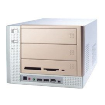
Chapter 1 1.1 Introduction Unlike the traditional PC, the MPC 400 comes with a fancy design case and multimedia I/O ports for quick connection and use. Front Panel Power Switch Eject/Stop Optical SPDIF-in Mic-in USB x 2 J1394-2 Headphone J1394-1... - Page 10 Back Panel Mouse Power Jack Power Voltage Switch Serial Port VGA Port Keyboard ATTENTION!!! Check the AC power voltage switch on the back panel. Select the voltage that is appropriate to the country you are in. LAN Port Parallel Port Speaker-out Optical SPDIF-out USB x 2...
-
Page 11: System Specification
Chapter 1 1.2 System Specification - MS-6749 (Proprietary F/F), 185 x 290 mm (4 layer) CPU: - Support Socket 462 for AMD Chipset: - VIA VT8205A2(KM400)+VT8235CD Memory: - DDR 333 x 2, support memory up to 2.0GB On-Board Audio: - AC’ 97 Codec integrated in ALC 658, support 5.1 channel , SPDIF In/Out. On-Board VGA: - Integrated (AGP 8X) ** On-Board VGA memory: None... - Page 12 - Front Panel: Mic in/Headphone x 1, USB x 2, SPDIF/I x 1, 1394 x 1 (4-pin), 1394 x 1(6-pin) BIOS - 2MB Flash Clock Generator - Integrated in ICS/ICS94230 Others - Microsoft PC 2001 ® - LAN Wake Up Function - Suspend to RAM/Disk function - Top Tech III (Thermal Overheat Protection Technology) - PC Alert System Hardware Monitor...
-
Page 13: Chapter 2. Introducing Mainboard
Introducing Mainboard Introducing Mainboard Introducing Mainboard Introducing Mainboard Introducing Mainboard 2.1 Mainboard Layout 2.1 Mainboard Layout 2.1 Mainboard Layout 2.1 Mainboard Layout 2.1 Mainboard Layout 2.2 CPU 2.2 CPU 2.2 CPU 2.2 CPU 2.2 CPU 2.3 Memory 2.3 Memory 2.3 Memory 2.3 Memory 2.3 Memory 2.4 Power Supply... -
Page 14: Mainboard Layout
Chapter 2 2.1 Mainboard layout MS-6749 v1.X Mainboard ○ ○ ○ ○ ○ ○ ○ ○ ○ ○ ○ ○ ○ ○ ○ ○ ○ ○ ○ ○ ○ ○ ○ ○ ○ J9: Front I/O Connector J8: Control Board Connector JFP1: Front Panel Power Connector J2: USB Connector (reserved) -
Page 15: Cpu
2.2 CPU The system supports AMD processors in the 462-pin package. The mainboard uses a CPU socket called Socket 462 for easy CPU installation. When you are installing the CPU, make sure the CPU has a heat sink and a cooling fan attached on the top to prevent overheating. - Page 16 Chapter 2 CPU Installation Procedures Please turn off the power and unplug the power cord before install- ing the CPU. Pull the lever sideways away from the socket. Make sure to raise the lever up to a 90-degree angle. Look for the gold arrow. The gold arrow should point towards the lever pivot.
-
Page 17: Memory
2.3 Memory The mainboard provides 2 slots for 184-pin DDR SDRAM DIMM (Double In-Line Memory Module) modules and supports the memory size up to 2GB. You can install PC2700/DDR333, PC2100/DDR266 modules into the DDR DIMM slots (DIMM1&DIMM2). Introduction to DDR SDRAM DDR (Double Data Rate) SDRAM is similar to conventional SDRAM, but doubles the rate by transferring data twice per cycle. -
Page 18: Power Supply
Chapter 2 2.4 Power Supply The system is equipped with a 200W(PFC) ATX power supply. The power cord of power supply has been connected to the connector JWR1 on the mainboard when shipped out. Except the 20-pin connector JWR1, you can find another 4-pin power connector JPW1 on the mainboard. -
Page 19: Front Panel
2.5 Front panel The Front Panel is independent and extended from the mainboard. It’s connected to the Front I/O Connector on the mainboard. You can find the following ports on the Front Panel. Optical SPDIF-In Mic-In Head-Phone IEEE 1394 Port: J1394-2 The mainboard provides two IEEE 1394 ports. -
Page 20: Ieee 1394 Port: J1394-1
Chapter 2 IEEE 1394 Port: J1394-1 The bigger 6-pin IEEE 1394 Port on the back panel is designed for you to connect to IEEE 1394 devices without external power. That means the mainboard can provide the power for the devices connected to this port. Software Support IEEE 1394 Driver is provided by Windows ®... -
Page 21: Mic-In/Head-Phone
Mic-in/Head-Phone Mic-in is a connector for microphone. Head-Phone is a connector for Speakers or Headphones. OPTICAL SPDIF-in The OPTICAL connector allows you to receive the audio file of SPDIF interface for recording and playing. The SPDIF (Sony & Philips Digital Interface) is developed jointly by the Sony and Philips corporations . -
Page 22: Back Panel
Chapter 2 2.6 Back panel The Back Panel provides the following ports: Mouse Serial Port Keyboard USB x 2 VGA Port Serial Port The mainboard offers a 9-pin male DIN serial port . The port is 16550A high speed communication ports that sends/receives 16 bytes FIFOs. You can attach a serial mouse or other serial devices directly to the connector. -
Page 23: Mouse/Keyboard Connectors
Mouse/Keyboard Connectors The mainboard provides two standard mini DIN connectors for attaching PS/2 mouse and keyboard. You can plug a PS/2 ® into the connector. PS/2 Mouse (6-pin Female) PS/2 Keyboard (6-pin Female) VGA Port The mainboard provides one DB 15-pin female connector to connect a VGA monitor. -
Page 24: Lan Port
Chapter 2 LAN Port The mainboard provides one standard RJ-45 jack for connection to Local Area Network (LAN). You can connect a network cable to the LAN jack. S-Video Out Connector You can connect to a TV or video device to S-Video out connector for video-out function which allows you to output the image to a TV or video device. -
Page 25: Parallel Port
Parallel Port The mainboard provides a 25-pin female centronic connector as LPT. A parallel port is a standard printer port that supports Enhanced Parallel Port (EPP) and Extended Capabilities Parallel Port (ECP) mode. ○ ○ ○ ○ ○ ○ ○ ○ ○ ○ ○ ○ ○ ○ ○ ○ ○ ○ ○ ○ ○ ○ ○ ○ ○ Pin Definition SIGNAL DESCRIPTION... -
Page 26: Usb Ports
Chapter 2 USB Ports The mainboard provides two USB2.0 EHCI/USB1.1 OHCI Universal Se- rial Bus root for attaching USB devices such as keyboard, mouse or other USB- compatible devices. You can plug the USB device directly into the connector. USB Ports Audio Port Speaker-out is a connector for Speakers or Headphones. -
Page 27: Connectors
2.7 Connectors IDE Connectors: IDE1 & IDE2 The mainboard has a 32-bit Enhanced PCI IDE and Ultra DMA 33/66/100/ 133 controller that provides PIO mode 0~4, Bus Master, and Ultra DMA/33/66/ 100/133 function. The two connectors on the mainboard allows you to connect to two IDE devices. -
Page 28: Cd-In Connector: Jcd1
Chapter 2 CD-in Connector: JCD1 The connector is for CD-ROM audio connector. Standby Power Connector: U11 The mainboard provides a connector to connect the Standby power. CPU/System Fan Connectors: CPUFAN1/CN31/CN30 The CPU and System Fan connectors support system cooling fans with +12V that is controlled by PWM. -
Page 29: Front Panel Power Connector: Jfp1
Front Panel Power Connector: JFP1 The mainboard provides a Front Panel connector for electrical connec- tion to the Front Panel switches and LEDs. JFP1 is compliant with Intel Panel I/O Connectivity Design Guide. JFP1 SIGNAL HD_LED_P FP PWR/SLP HD_LED_N FP PWR/SLP RST_SW_N PWR_SW_P RST_SW_P... -
Page 30: Jumper
Chapter 2 2.8 Jumpers There is a CMOS RAM on board that has a power supply from external battery to keep the data of system configuration. With the CMOS RAM, the system can automatically boot OS every time it is turned on. That battery has long life time for at least 2 years. -
Page 31: Slots
2.9 Slots PCI Slot The PCI slot allows you to insert PCI card or TV Tuner card. When adding or removing expansion cards, make sure that you unplug the power supply first. Meanwhile, read the documentation for the expansion card to make any neces- sary hardware or software settings NOTE: You can install the OPTIONAL MS8606 card into the PCI slot to enjoy watching TV. -
Page 32: Chapter 3: Setting Bios Function
Setting BIOS Function Setting BIOS Function 3.1 Entering Setup 3.2 The Main Menu 3.3 Standard CMOS Features 3.4 Advanced BIOS Features 3.5 Advanced Chipset Features 3.6 Power Management Features 3.7 PnP/PCI Configurations 3.8 Integrated Peripherals 3.9 PC Health Status 3.10 System Information... -
Page 33: Entering Setup
Chapter 3 3.1 Entering Setup Power on the computer and the system will start POST (Power On Self Test) process. When the message below appears on the screen, press <DEL> key to enter Setup. Press DEL to enter SETUP If the message disappears before you respond and you still wish to enter Setup, restart the system by turning it OFF and On or pressing the RESET button. -
Page 34: Getting Help
Getting Help After entering the Setup menu, the first menu you will see is the Main Menu. Main Menu The main menu lists the setup functions you can make changes to. You can use the control keys ( highlighted setup function is displayed at the bottom of the screen. Sub-Menu If you find a right pointer symbol (as shown in the right view) appears to the left of certain fields that means a sub-menu containing additional options can be... -
Page 35: The Main Menu
Chapter 3 3.2 The main menu Once you enter BIOS CMOS Setup Utility, the Main Menu (Figure 1) will appear on the screen. The Main Menu allows you to select from twelve setup functions and two exit choices. Use arrow keys to select among the items and press <Enter>... - Page 36 Setting BIOS Function PnP/PCI Configurations This entry appears if your system supports PnP/PCI. Integrated Peripherals Use this menu to specify your settings for integrated peripherals. PC Health Status This entry shows your PC health status. System Information This entry shows the system information. Set Supervisor Password Use this menu to set Supervisor Password.
-
Page 37: Standard Cmos Features
Chapter 3 3.3 standard cmos features The items in Standard CMOS Features Menu are divided into 14 categories. Each category includes no, one or more than one setup items. Use the arrow keys to highlight the item and then use the <PgUp> or <PgDn> keys to select the value you want in each item. - Page 38 If you select Manual, related information is asked to be entered to the following items. Enter the information directly from the keyboard. This information should be provided in the documentation from your hard disk vendor or the system manufacturer. Access Mode Capacity Cylinder Head...
-
Page 39: Advanced Bios Features
Chapter 3 3.4 advanced bios features Quick Boot Setting the item to Enabled allows the system to boot within 5 seconds since it will skip some check items. Available options: Enabled, Disabled. Full Screen Logo Show This item enables you to show the company logo on the bootup screen. Settings are: Shows a still image (logo) on the full screen at boot. - Page 40 Boot Device Priority 1st/2nd/3rd Boot Device The items allow you to set the sequence of boot devices where BIOS attempts to load the disk operating system. If you select boot from USB device, USB Device Legacy Support must be set to Enabled. Try Other Boot Devices Setting the option to Enabled allows the system to try to boot from other device if the system fails to boot from the 1st/2nd/3rd boot device.
- Page 41 Chapter 3 Security Option This specifies the type of BIOS password protection that is implemented. Set- tings are described below: Option Description Setup The password prompt appears only when end users try to run Setup. System A password prompt appears every time when the com- puter is powered on or when end users try to run Setup.
-
Page 42: Advanced Chipset Features
Setting BIOS Function 3.5 advanced chipset features NOTE: Change these settings only if you are familiar with the chipset. Spread Spectrum This item is used to enable or disable the FSB clock generator’ s Spread Spectrum feature. When overclocking the FSB, always set it to Disabled. Options: Disabled, ±0.25%, ±0.5%, ±0.75%. - Page 43 Chapter 3 Configure SDRAM Timing by SPD Selects whether DRAM timing is controlled by the SPD (Serial Presence Detect) EEPROM on the DRAM module. Setting to SPD enables SDRAMFrequency, SDRAM CAS Latency and SDRAM Bank Interleave automatically to be determined by BIOS based on the configurations on the SPD.
- Page 44 Setting BIOS Function SDRAM Burst Length This setting allows you to set the size of Burst-Length for DRAM. Bursting feature is a technique that DRAM itself predicts the address of the next memory location to be accessed after the first address is accessed. To use the feature, you need to define the burst length, which is the actual length of burst plus the starting address and allows internal address counter to properly generate the next memory location.
- Page 45 Chapter 3 AGP Fast Write This option enables or disables the AGP Fast Write feature. The Fast Write technology allows the CPU to write directly to the graphics card without passing anything through the system memory and improves the AGP 4X speed.
- Page 46 Setting BIOS Function TV-Out Function Press <Enter> to enter the sub-menu and the following screen appears: Boot Display Device This item allows you to select the Boot Display Device. Options: CRT, TV Type Select the TV standard which is used as the video signal format of your TV if you have connected a TV to the system.
-
Page 47: Power Management Features
Chapter 3 3.6 Power management features Sleep State This item specifies the power saving modes for ACPI function. Options are: The S1 sleep mode is a low power state. In this state, no S1/POS system context is lost (CPU or chipset) and hardware main tains all system context. - Page 48 Set WakeUp Events Press <Enter> to enter the sub-menu and the following screen appears: Wake Up On PME, Wake Up By Keyboard (with “Wake-Up Key” and “Wake-Up Password”), Wake Up By PS/2 Mouse These fields specify whether the system will be awakened from power saving modes when activity or input signal of the specified hardware peripheral or component is detected.
-
Page 49: Pnp/Pci Configurations
Chapter 3 3.7 PNP/PCI Configurations Clear NVRAM The ESCD (Extended System Configuration Data) NVRAM (Nonvolatile Random Access Memory) is where the BIOS stores resource information for both PNP and non-PNP devices in a bit string format. When the item is set to Yes, the system will reset ESCD NVRAM right after the system is booted up and then set the setting of the item back to No automatically. -
Page 50: Integrated Peripherals
Setting BIOS Function 3.8 Integrated peripherals On-Chip IDE This setting controls the onboard IDE controller. Setting options: Disabled, Primary, Secondary, Both. Onboard LAN Controller This setting controls the onboard LAN controller. Setting options: Disabled, Enabled. OnBoard LAN P.M.E This setting controls the power management function of LAN. Setting “Enabled ”... - Page 51 Chapter 3 OnBoard AC’ 97 Audio Select Enabled to use the audio capabilities of your system. Most of the follow- ing fields do not appear when this field is Disabled. OnBoard 1394 Controller This setting controls the onboard 1394 device. Setting options: Disabled, Enabled. USB Controller This setting is used to enable/disable the onboard USB controller.
- Page 52 Setting BIOS Function Serial Port 1 These items specify the base I/O port addresses of the onboard Serial Port 1 (COM A)/Serial Port 2 (COM B). Selecting Auto allows AMIBIOS to automatically determine the correct base I/O port address. Settings: Auto, 3F8/COM1, 2F8/COM2, 3E8/COM3, 2E8/COM4 and Disabled.
-
Page 53: Pc Health Status
Chapter 3 3.9 PC health status System/CPU Temperature, CPU Fan1/CPU Fan2 Speed, Vcore, +5.0V, +12.0V, -12.0V, -5.0V, Battery, +5V SB These items display the current status of all of the monitored hardware devices/ components such as CPU voltages, temperatures and all fans’ speeds. 3-22... -
Page 54: System Information
Setting BIOS Function 3.10 System Information Product Name, System BIOS Version, BlueBird F/W Version, Processor Type, Processor Speed, Total Memory These items shows the information about the system status, such as product name, BIOS version, processor type, processor speed and total memory. 3-23...