Table of Contents
Advertisement
Quick Links
Instruction Manual
D103435X012
Fisher
V150E Expanded Outlet Vee-Ball
™
Valve
Contents
Introduction
. . . . . . . . . . . . . . . . . . . . . . . . . . . . . . . . .
Scope of Manual
. . . . . . . . . . . . . . . . . . . . . . . . . . . . .
. . . . . . . . . . . . . . . . . . . . . . . . . . . . . . . . .
. . . . . . . . . . . . . . . . . . . . . . . . . . . . . . .
. . . . . . . . . . . . . . . . . . . . . . . . . . . . . . . . . . . .
. . . . . . . . . . . . . . . . . . . . . . . . . . . . . . . . . .
. . . . . . . . . . . . . . . . . . . . . . . . . . . .
. . . . . . . . . . . . . . . . . . . . . . . . . . . . . . . .
. . . . . . . . . . . . . . . . . . . . . . . . . . . . . . . . . . . . .
. . . . . . . . . . . . . . . . . . . . . . . . . . . . . . . . . . . . .
Introduction
Scope of Manual
This instruction manual provides installation, operation, maintenance, and parts information for the Fisher Vee-Ball
V150E rotary control valve (see figure 1).
For information on ENVIRO-SEAL™ packing, see the ENVIRO-SEAL Packing System for Rotary Valves instruction
manual, D101643X012. Refer to separate manuals for information concerning the actuator, positioner and
accessories.
Do not install, operate, or maintain a V150E valve without being fully trained and qualified in valve, actuator, and
accessory installation, operation, and maintenance. To avoid personal injury or property damage, it is important to
carefully read, understand, and follow all the contents of this manual, including all safety cautions and warnings. If you
have any questions about these instructions, contact your
proceeding.
Description
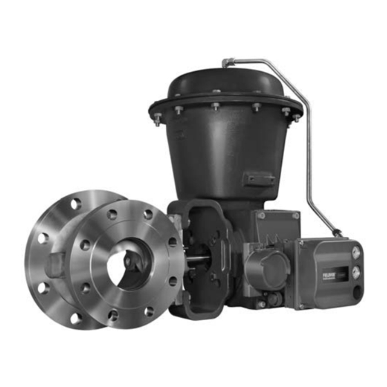
V150E Vee-Ball valves (figure 1) with a V-notch ball are used in throttling service. The V150E valve is a raised-face
flanged construction. The splined valve shaft connects to a variety of Fisher rotary-shaft actuators.
www.Fisher.com
. . . . . . . . . . . . . . . . . . . . . . . . .
. . . . . . . . . . . . . . . . . . . . .
. . . . . . . . . . . . . . . . .
. . . . . . . . . . . . . . .
. . . . . . . . . . . . . . . . .
Figure 1. Fisher V150E Expanded Outlet Vee-Ball
Valve with 2052 Actuator and FIELDVUE™ DVC6200
1
Digital Valve Controller
1
1
2
2
5
5
7
12
15
16
16
16
21
22
W9915
Emerson sales office
Control
™
or Local Business Partner before
V150E Valve
July 2017
Advertisement
Table of Contents

Related Manuals for Emerson Fisher V150E


Summary of Contents for Emerson Fisher V150E
-
Page 1: Table Of Contents
™ Valve Contents Figure 1. Fisher V150E Expanded Outlet Vee-Ball Valve with 2052 Actuator and FIELDVUE™ DVC6200 Introduction ....... . . -
Page 2: Specifications
Instruction Manual V150E Valve July 2017 D103435X012 Table 1. Specifications Valve Sizes and End Connection Styles Actuator Mounting DN J 80x100, J 100x150, J 150x200, J 200x250, Standard valve construction is for right-hand 250x300 and NPS J 3x4, J 4x6, J 6x8, J 8x10, mounting, as viewed from upstream end of valve with 10x12 flanged valves that mate with J PN 10/16, the shaft horizontal. - Page 3 To avoid possible personal injury and because some valve/trim material combinations are limited in their pressure drop and temperature ranges, do not apply any other conditions to the valve without first contacting your Emerson sales office or Local Business Partner. WARNING The valve drive shaft is not necessarily grounded to the pipeline when installed.
- Page 4 Instruction Manual V150E Valve July 2017 D103435X012 CAUTION Ensure the valve and adjacent pipelines are free of foreign material that could damage the valve seating surfaces. 7. Be certain the valve and adjacent pipelines are free of any foreign material that could damage the valve sealing surfaces.
-
Page 5: Maintenance
Instruction Manual V150E Valve D103435X012 July 2017 Maintenance Valve parts are subject to normal wear and must be inspected and replaced as necessary. The frequency of inspection and replacement depends upon the severity of service conditions. Key numbers in this procedure are shown in figure 10, unless otherwise noted. WARNING The Vee‐ball closes with a shearing, cutting motion, which could result in personal injury. - Page 6 Instruction Manual V150E Valve July 2017 D103435X012 Disassembly WARNING Observe the steps in the WARNING at the beginning of the Maintenance section. 1. Isolate the control valve from the line pressure, release pressure from both sides of the valve body, and drain the process media from both sides of the valve.
-
Page 7: Replacing The Hd Ball Seal
Instruction Manual V150E Valve D103435X012 July 2017 drive shaft or packing box wall; scratching these surfaces could cause leakage. Clean all accessible metal parts and surfaces to remove particles that would prevent the packing from sealing. Assembly If the valve is equipped with the ENVIRO‐SEAL packing system, refer to the ENVIRO‐SEAL Packing System for Rotary Valves instruction manual, D101643X012, for assembly. - Page 8 Instruction Manual V150E Valve July 2017 D103435X012 Figure 3. Packing Arrangements PACKING FOLLOWER (KEY 17) PACKING FOLLOWER (KEY 17) PACKING RING (KEY 35) PACKING SET (KEY 16) PACKING PACKING BOX RING (KEY 39) BOX RING (KEY 39) PTFE V‐RING PACKING GRAPHITE RIBBON PACKING FOR V150E FOR V150E...
- Page 9 Instruction Manual V150E Valve D103435X012 July 2017 Figure 4. Typical Fisher V150E Valve Showing Pry Bar PRY IN THIS DIRECTION THRUST AND BEARING SURFACE ACTUATOR SIDE OF VALVE BALL GE44766-A b. For NPS 6x8 and larger valves, the HD seal can be removed through the outlet end of the valve with the ball installed.
- Page 10 Instruction Manual V150E Valve July 2017 D103435X012 D If the seal is difficult to push out, it is recommended that a seal removal plate be used to press the HD metal seal out of the valve body. Refer to figure 6 for dimensions of the seal removal plate. Figure 5.
- Page 11 Instruction Manual V150E Valve D103435X012 July 2017 Figure 6. HD Seal Removal Plate Dimensions DIMENSION A 6.4 mm VALVE SIZE, Minimum‐Maximum, Minimum‐Maximum, (0.250 INCHES) Inches MINIMUM 75.9‐76.2 2.990‐3.000 95.0‐95.3 3.740‐3.750 126.7‐127.0 4.990‐5.000 8x10 158.5‐158.8 6.240‐6.250 10x12 212.5‐212.7 8.365‐8.375 A5544 Installing HD metal seals Refer to figures 6, and 13 for key number locations during seal installation.
-
Page 12: Bearing And Ball Maintenance
Instruction Manual V150E Valve July 2017 D103435X012 Bearing and Ball Maintenance WARNING Before performing the steps in this section, observe the WARNING at the beginning of the Maintenance section on page 5. Procedures for disassembly and assembly of the bearings and ball cannot be accomplished until the shaft and valve packing are removed from the valve. - Page 13 Instruction Manual V150E Valve D103435X012 July 2017 8. Carefully remove the follower shaft and ball (key 2) from the outlet end of the valve body. 9. The bearings are not pressed in, so they can be removed with minimal force. Be careful not to damage the machined surfaces of the bearing bore if prying is required.
- Page 14 Instruction Manual V150E Valve July 2017 D103435X012 Figure 7. Informational Tag GE11636‐A FOR STANDARD RIGHT/LEFT HAND BALL GE11637‐A FOR OPTIONAL LEFT HAND BALL Installing the Taper Key Current standard construction materials for all valves require the taper key (key 4, figure 9) to be tack welded in place after properly seating, using the following procedure.
-
Page 15: Actuator Mounting
Instruction Manual V150E Valve D103435X012 July 2017 15. When the above conditions are met, tack weld the taper key (key 4) to the ball ear on the head end of the key (see figures 8 and 10). Use a: D 1/8 inch diameter weld on NPS 3x4, 4x6, 6x8 valves, D 3/16 inch diameter weld on NPS 8x10 and 10x12 valves 16. -
Page 16: Determining Mounting Position
WARNING Use only genuine Fisher replacement parts. Components that are not supplied by Emerson Automation Solutions should not, under any circumstances, be used in any Fisher valve, because they may void your warranty, might adversely affect the performance of the valve, and could cause personal injury and property damage. - Page 17 Instruction Manual V150E Valve D103435X012 July 2017 Figure 9. Index Marks for Actuator Lever Orientation GG08274-A...
- Page 18 Instruction Manual V150E Valve July 2017 D103435X012 Figure 10. Exploded View, Fisher V150E GG07077_A PARTS NOT SHOWN: KEY 30, 31, 35, 36, AND 57...
- Page 19 V150E Valve D103435X012 July 2017 Figure 11. Fisher V150E Dimensions MATCHES CL150 RF, PN10 AND 16, OR JIS 10K FLANGES S DIA GE44656_A Table 6. Fisher V150E Dimensions (see figure 11) APPROXIMATE WEIGHT E (optional) 80x100 19.1 31.8 14.2 1/2 NPT 100x150 19.1...
- Page 20 Instruction Manual V150E Valve July 2017 D103435X012 Figure 12. Centering Template in Use 19B8493 E0740 Figure 13. Centering Template Dimensions VALVE SIZE 80x100 100x150 150x200 200x250 250x300 Inches 5.00 2.50 0.94 1.50 19B8493 E0741 6.19 3.25 1.42 1.75 8.50 4.62 0.82 2.00 8x10...
-
Page 21: Parts Kits
Instruction Manual V150E Valve D103435X012 July 2017 Retrofit Kits for ENVIRO‐SEAL Packing Retrofit kits include parts to convert existing V150E valves with shallow (single packing depth) packing box to the ENVIRO‐SEAL packing box construction. Retrofit kits include single PTFE packing. See following table. ENVIRO‐SEAL Packing Retrofit Kits SHAFT DIAMETER PART NUMBER... -
Page 22: Parts List
If you need a valve body as a replacement part, 19 Packing Follower Stud order by valve size, serial number, and desired 20 Packing Follower Nut valve body material. Contact your Emerson sales office or Local 23 Actuator Mounting Screw Business Partner for assistance. 24 Actuator Mounting Nut 2... - Page 23 Instruction Manual V150E Valve D103435X012 July 2017 ENVIRO‐SEAL Packing System Description Part Number 107* Packing Box Ring (Parts in all Vee‐Ball Valves) W/single and double PTFE packing NPS 3x4 and 4x6 16A6084X012 (figure 3) NPS 6x8 16A6085X012 108* Packing Ring (2 req'd) Description Part Number W/double PTFE packing...
- Page 24 Fisher, Vee-Ball, ENVIRO-SEAL, and FIELDVUE are marks owned by one of the companies in the Emerson Automation Solutions business unit of Emerson Electric Co. Emerson Automation Solutions, Emerson, and the Emerson logo are trademarks and service marks of Emerson Electric Co. All other marks are the property of their respective owners.