Table of Contents
Advertisement
Instruction Manual
D100423X012
Fishert V500 Rotary Globe Control Valve
Contents
. . . . . . . . . . . . . . . . . . . . . . . . . . . . . . . . .
Scope of Manual
. . . . . . . . . . . . . . . . . . . . . . . . . . . . .
. . . . . . . . . . . . . . . . . . . . . . . . . . . . . . . . .
. . . . . . . . . . . . . . . . . . . . . . . . . . . . . . .
. . . . . . . . . . . . . . . . . . . . . . . . . . . . . . . . . .
. . . . . . . . . . . . . . . . . . . . . . . . . . . . . . . . .
. . . . . . . . . . . . . . . . . . . . . . . . . . . . . . .
. . . . . . . . . . . . . . . . . . . . . . . . . . . . . . . . . . .
. . . . . . . . . . . . . . . . . . . . . . . . . . . . . . . . . . .
Introduction
Scope of Manual
This instruction manual provides installation, operation, maintenance, and parts ordering information for NPS 1
through 8 Fisher V500 eccentric plug rotary control valves. Refer to separate manuals for information concerning the
actuator and accessories.
Do not install, operate, or maintain a V500 valve without being fully trained and qualified in valve, actuator, and
accessory installation, operation, and maintenance. To avoid personal injury or property damage, it is important to
carefully read, understand, and follow all the contents of this manual, including all safety cautions and warnings. If you
have any questions about these instructions, contact your
proceeding.
Unless otherwise noted, all NACE references are to NACE MR0175-2002.
Description
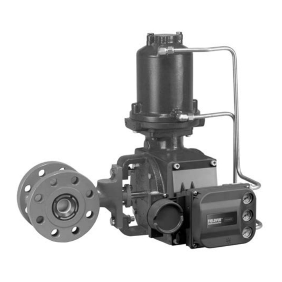
The V500 rotary control valve is a flanged (figure 1) or flangeless valve with a self-centering seat, eccentrically rotating
plug, and splined valve shaft. Suitable for forward or reverse flow use, this valve mates with a variety of actuators to
provide throttling or on-off service. Both flanged and flangeless valves mate with CL150, 300, or 600 raised face
pipeline flanges or DIN PN10 through PN100 flanges.
. . . . . . . . . . . . . . . . . . . . . . . . .
. . . . . . .
. . . . . . . . . . . . . . . . . . . .
. . . . . . . . . . . . . . . .
. . . . . . . . . . . .
Figure 1. Fisher V500 Flanged Rotary Control Valve
with 1061 Actuator and FIELDVUE™ DVC6200 Digital
1
Valve Controller
1
1
2
2
7
8
. . . .
10
15
20
21
21
21
22
24
W8380-1
Emerson sales office
or Local Business Partner before
V500 Valve
July 2017
Advertisement
Table of Contents

Related Manuals for Emerson Fisher V500


Summary of Contents for Emerson Fisher V500
-
Page 1: Table Of Contents
Scope of Manual This instruction manual provides installation, operation, maintenance, and parts ordering information for NPS 1 through 8 Fisher V500 eccentric plug rotary control valves. Refer to separate manuals for information concerning the actuator and accessories. Do not install, operate, or maintain a V500 valve without being fully trained and qualified in valve, actuator, and accessory installation, operation, and maintenance. -
Page 2: Specifications
J Left‐hand or J right‐hand as viewed from the flangeless valve bodies). DIN PN10 through PN100 upstream side of the valve. See figure 2 flanges also available; consult your Emerson sales office or Local Business Partner. Valve Plug Rotation Counterclockwise to close (when viewed from... - Page 3 Since some valve body/trim material combinations are limited in their pressure drop and temperature ranges, do not apply any other conditions to the valve without first contacting your Emerson sales office or Local Business Partner. Table 2. Shaft Diameter and Approximate Weights...
- Page 4 Instruction Manual V500 Valve July 2017 D100423X012 Figure 2. Index Marks for Actuator Lever Orientation 43A5323‐D C0586‐1...
- Page 5 Instruction Manual V500 Valve July 2017 D100423X012 Table 3. Line Stud (Key 36) Valve Size Bolt Length Pressure Rating Bolt Size Inches CL150 5/8-11 UNC 10.62 CL300 3/4-10 UNC 11.12 CL600 3/4-10 UNC 11.50 CL150 5/8-11 UNC 11.44 CL300 3/4-10 UNC 12.12 CL600 7/8- 9 UNC...
- Page 6 Instruction Manual V500 Valve July 2017 D100423X012 Figure 4. Optional Shaft‐to‐Body Bonding Strap Assembly ACTUATOR VALVE BODY 37A6528‐A VIEW A‐A A3143‐2 Note For best shutoff performance and to reduce bearing wear, it is recommended that you install the valve shaft in a horizontal direction.
-
Page 7: Maintenance
If the valve has ENVIRO‐SEALt live‐loaded packing installed readjustment will probably not be required. See the Emerson Automation Solutions instruction manual entitled ENVIRO‐SEAL Packing System for Rotary Valves (D101643X012) for packing instructions. If you wish to convert your present packing arrangement to ENVIRO‐SEAL packing, refer to the retrofit kits listed in the Parts Kit section later in this manual. -
Page 8: Packing Maintenance
Instruction Manual V500 Valve July 2017 D100423X012 D Vent the power actuator loading pressure and relieve any actuator spring precompression. D Use lock‐out procedures to be sure that the above measures stay in effect while you work on the equipment. D The valve packing area may contain process fluids that are pressurized, even when the valve has been removed from the pipeline. - Page 9 Instruction Manual V500 Valve July 2017 D100423X012 Removing the Packing 1. Isolate the control valve from the line pressure, release pressure from both sides of the valve, and drain the process media from both sides of the valve. If using a power actuator, also shut off all pressure lines to the power actuator, release all pressure from the actuator.
-
Page 10: Replacing Retainer, Seat Ring, And Face Seals
Instruction Manual V500 Valve July 2017 D100423X012 7. When the control valve is being put back into operation, check the packing follower for leakage, and retighten the packing nuts as necessary. Replacing Retainer, Seat Ring, and Face Seals This procedure is to be performed if the control valve is not shutting off properly, if the port diameter is to be changed by installing a different seat ring, or if seat ring inspection is necessary. - Page 11 Instruction Manual V500 Valve July 2017 D100423X012 Figure 5. Packing Arrangements PACKING RING (KEY 13) ZINC PACKING WASHERS RINGS (KEY 28) (KEY 13) LANTERN RING LANTERN (KEY 18) RINGS ZINC (KEY 18) WASHERS ZINC PACKING PACKING (KEY 28) WASHER BOX RING BOX RING (KEY 28) (KEY 17)
- Page 12 Instruction Manual V500 Valve July 2017 D100423X012 Figure 5. Packing Arrangements (continued) PACKING FLANGE STUD (KEY 100) PACKING FLANGE NUT (KEY 101) PACKING FLANGE (KEY 102) GRAPHITE PACKING SET (KEY 105) PACKING BOX RING (KEY 107) SPRING PACK ASSEMBLY GRAPHITE PACKING (KEY 103) IN A STANDARD DEPTH BOX PTFE PACKING...
- Page 13 Instruction Manual V500 Valve July 2017 D100423X012 Table 6. Data for Making Retainer Tool VALVE SIZE, (HEX) (SQUARE) (HEX) (SQUARE) Inches 26.9 28.4 28.4 ‐ ‐ ‐ 1.06 1.12 1.12 ‐ ‐ ‐ 1-1/2 36.6 28.4 38.1 ‐ ‐ ‐ 1.44 1.12 1.50...
-
Page 14: Proceeding
Instruction Manual V500 Valve July 2017 D100423X012 Assembly of Retainer, Seat Ring, and Face Seals WARNING Seat ring installation requires that the valve plug (key 2) remain in the open position. To avoid personal injury or damage to tools, valve parts, or other items resulting from plug closing, prevent plug travel by using travel stops, manual actuators, constant supply pressure to a pneumatic actuator, or other steps as appropriate. -
Page 15: Replacing Valve Plug, Shaft, And Bearings
3. With the valve body (key 1) out of the pipeline, loosen the packing nuts (key 16). If the packing is to be reused, do not remove it. However, Emerson Automation Solutions recommends that the packing be replaced whenever the drive shaft is removed. - Page 16 Instruction Manual V500 Valve July 2017 D100423X012 Figure 8. Detail of Valve Plug for Pin Removal DRIVE PINS OUT FROM THIS END (SMALLER HOLE) SLASH MARK ON SPLINED A3307‐1 END OF SHAFT Table 9. Data for Tapped Hole in Valve Shaft SHAFT DIAMETERS THREAD SIZE, Through Valve Body...
- Page 17 Instruction Manual V500 Valve July 2017 D100423X012 7. Remove the plug and thrust washer (key 12) from the valve body. Note Two shaft bearings (key 6) are located inside the valve body on either side of the valve plug. Only one of these two bearings is identified by key 6.
- Page 18 Instruction Manual V500 Valve July 2017 D100423X012 Figure 9. Ram Dimension for Bearing Removal (also see table 10) A3308 Assembly of Valve Plug, Shaft, and Bearings Note Before starting to assemble the valve components, place the valve body (key 1) on a flat surface with the retainer (key 5) facing down as shown in figure 10.
- Page 19 Instruction Manual V500 Valve July 2017 D100423X012 Figure 10. Detail of Valve Plug for Pin Insertion PINS GO IN FROM THIS END (LARGER HOLE) SLASH MARK ON SPLINED END OF SHAFT BENCH A3309‐1 Note Before proceeding, inspect the valve plug position once again to ensure the correct orientation as described in step 6. If the valve plug is not properly installed, it will not rotate properly and will not shutoff in service.
-
Page 20: Adjusting Actuator Travel
Instruction Manual V500 Valve July 2017 D100423X012 NPS 1 through 2 VTC valve plugs are sold only as a set that includes N10276 pins. Use only the pins that are furnished with the set. Components of the VTC valve plug assembly for the NPS 3 through 8 cannot be repaired in the field. 11. -
Page 21: Changing Valve Flow Direction
WARNING Use only genuine Fisher replacement parts. Components that are not supplied by Emerson Automation Solutions should not, under any circumstances, be used in any Fisher valve, because they may void your warranty, might adversely affect the... -
Page 22: Parts Kits
Leakoff packing and sealed bearings Deep packing box with both lube and end tapping Purged bearing and single packing for purged bearings Deep packing box with both lube and end tapping 1. Please contact your Emerson sales office for more information. - Page 23 Instruction Manual V500 Valve July 2017 D100423X012 Figure 11. Fisher V500 Rotary Control Flange Valve, NPS 1 and 1-1/2 DOUBLE PACKING OPTIONAL PIPE PLUG OPTIONAL SEALED BEARING V APPLY LUBRICANT 39A9677‐D...
-
Page 24: Parts List
Thrust Washer Part numbers are shown for recommended spares only. For part 13* Packing Set numbers not shown, contact your Emerson sales office or Local Business PTFE & carbon‐filled V‐ring set (conductive) Partner. Single & purged bearing construction ‐ 1 req'd Double ‐... - Page 25 Instruction Manual V500 Valve July 2017 D100423X012 Figure 13. Fisher V500 Rotary Control Valve, NPS 2, 3, 4, 6, and 8 DOUBLE PACKING SEALED OPTIONAL BEARING PIPE PLUG OPTIONAL MEASURE GAP HERE APPLY LUB 49A3686‐F...
- Page 26 Instruction Manual V500 Valve July 2017 D100423X012 Description Description 13* Packing Set (continued) PTFE/bound composition rings 28* Packing Washer (not shown) Single & purged bearing construction Zinc (for graphite/ribbon pkg only) Conductive ‐ 3 req'd & graphite filament ring Single ‐ 3 req'd Nonconductive ‐...
- Page 27 Instruction Manual V500 Valve July 2017 D100423X012 Figure 14. ENVIRO‐SEAL Rotary Packing Arrangements with PTFE and Graphite Packing SINGLE PTFE PACKING STANDARD DEPTH BOX STACKING ORDER OF PTFE PACKING RINGS STACKING ORDER OF GRAPHITE PACKING RINGS GRAPHITE PACKING STANDARD DEPTH BOX NOTES: APPLY LUBRICANT.
-
Page 28: Www.fisher.com
Responsibility for proper selection, use, and maintenance of any product remains solely with the purchaser and end user. Fisher, FIELDVUE, and ENVIRO-SEAL are marks owned by one of the companies in the Emerson Automation Solutions business unit of Emerson Electric Co.