Table of Contents
Advertisement
Advertisement
Table of Contents

Related Manuals for MSI MEGA 651


Summary of Contents for MSI MEGA 651
- Page 2 Shielded interface cables and AC. power cord, if any, must be used in order to comply with the emission limits. VOIR LA NOTICE D’INSTALLATION AVANT DE RACCORDER AU RESEAU. Micro-Star International MEGA 651 Tested to comply with FCC Standard For Home or Office Use...
-
Page 3: Lithium Battery Statement
Lithium Battery Statement CAUTION Danger of explosion if battery is incorrectly replaced. Replace only with the same or equivalent type recommended by the manufactuer. Discard used bat- teries according to the manufacturer’s instructions. ® Macrovision Statement This product incorporates copyright protection technology that is protected by method claims of certain U.S. -
Page 4: Safety Instructions
Safety Instructions Always read the safety instructions carefully. Keep this User’s Manual for future reference. Keep this equipment away from humidity. Lay this equipment on a reliable flat surface before setting it up. The openings on the enclosure are for air convection hence protects the equipment from overheating. -
Page 5: Copyright Notice
Copyright Notice The material in this document is the intellectual property of MICRO-STAR INTERNATIONAL. We take every care in the preparation of this document, but no guarantee is given as to the correctness of its contents. Our products are under continual improvement and we reserve the right to make changes with- out notice. -
Page 6: Table Of Contents
Introduction Chapter 1. Getting Started...1-1 All-in-One Feature Set...1-2 Front Panel...1-3 Back Panel...1-3 System Specification...1-4 Performance PC ...1-6 Hi-Fi Audio...1-8 Home Theater...1-10 Chapter 2. Introducing Mainboard...2-1 Mainboard Layout...2-2 CPU/Memory...2-3 Introduction to DDR SDRAM...2-3 Power Supply...2-4 Front Panel...2-5 IEEE 1394 Port: J1394-2...2-5 IEEE 1394 Port: J1394-1...2-6 USB Ports...2-6 Mic-in/Head-Phone...2-7... - Page 7 IDE Connectors: CN22 & CN23...2-13 FDD Connector: CN10... 2-13 CD-in Connector: CN16...2-14 TV-Tuner Card Connector: CN13...2-14 CPU Fan Connector: CN15...2-14 Front Panel Power Connector: CN4...2-15 USB Card Reader Connector: CN6...2-15 LCM Connector: CN18...2-16 Modem Module Connector: CN21...2-16 Jumper...2-17 Clear CMOS Jumper: J2...2-17 Slots...2-18 PCI Slot...2-18 AGP Slot...2-18...
- Page 8 Standard CMOS Features...4-6 Advanced BIOS Features...4-8 Advanced Chipset Features...4-11 Integrated Peripherals...4-13 Power Management Setup...4-19 PNP/PCI Configurations...4-23 PC Health Status...4-25 Frequency/Voltage Control...4-26 Appendix. Using Mega Radio...A-1 Listening to Radio...A-2 Setting Memory Station...A-6 Recording Music...A-7 viii...
-
Page 9: Introduction
Introducing Y Introducing Y our Introducing Y Introducing Y Introducing Y “Digital Media Platform “Digital Media Platform ” ” ” ” ” “Digital Media Platform “Digital Media Platform “Digital Media Platform Introduction... - Page 10 Thank you for your purchasing of MEGA 651, the Best of Computing & Home Entertainment. Based on the design idea of consumer product, the MEGA 651 is not just a PC anymore. The “All-in-One” feature positions MEGA 651 as a Digital Media Platform.
- Page 11 - Media Center: Card Reader + 1394 + SPDIF I/O +PVR - Completed PC: Office + Game Machine A New Digital Media Form Factor from MSI That Allows You to - Control Live Television - Enjoy Home Theater (DVD + 5.1 Channel)
-
Page 12: Chapter 1. Getting Started
Getting Started Getting Started Getting Started Getting Started Getting Started 1.1 All-in- 1.1 All-in- 1.1 All-in-One Feature Set 1.1 All-in- 1.1 All-in- 1.2 System Specification 1.2 System Specification 1.2 System Specification 1.2 System Specification 1.2 System Specification 1.3 P 1.3 P erformance PC erformance PC 1.3 P... -
Page 13: All-In-One Feature Set
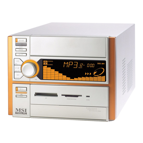
Chapter 1 1.1 All-in-one Feature Set The MEGA651 implements all the Hi-Fi Stereo into Home-PC with a fancy equalizer LCM and control panel in the front bezel. When PC is power off, you can use it just like a Hi-Fi Stereo with a remote controller. When PC is power on, you can use it for Home Theater and Media Center PC. -
Page 14: Front Panel
Front Panel Hi-Fi Power Switch IR Receiver Mode Eject/Stop Forward Play/Pause Backward Shuttle Controller PC Power Switch HDD LED PC Reset Optical SPDIF-in Back Panel Power Jack Serial Port VGA Port ○ ○ ○ ○ ○ ○ ○ ○ ○ ○ ○ ○ ○ ○ ○ ○ ○ ○ ○ ○ ○ ○ ○ ○ ○ J1394-2 USB x 2 Mic-in... -
Page 15: System Specification
Chapter 1 1.2 System Specification - MS-6760 (Proprietary F/F), 185 x 290 mm (4 layer) CPU: - Support Socket 478 for Pentium Chipset: - SiS 651 + SiS 962 Memory: - DDR 333 x 2, support memory up to 2.0GB On-Board Audio: - AC’97 Codec integrated in ALC 650, support 5.1 channel , SPDIF In/Out. - Page 16 On-Board Headers & Connectors - Rear Panel: Parallel Port x 1, Serial Port x 1, VGA x 1, PS/2 x 2, Mic in/Line in/ Line out x 1, USB x 2, LAN (RJ45) x 1, SPDIF/O x 1, Modem (RJ11) x 1 - Front Panel: Mic in/Headphone x 1, USB x 2, SPDIF/I x 1, 1394 x 1 (4-pin), 1394 x 1(6-pin) BIOS...
-
Page 17: Performance Pc
Chapter 1 1.3 Performance PC When PC is power on, the MEGA651 is your performance PC. Power on means “If the power button of PC is pressed, the Hi-Fi stereo has no function even you press the Hi-Fi button.” Press the Power button to start the PC function Features CPU support: Intel P4... - Page 18 Target Operating System -- Microsoft Windows XP Home Edition Security -- The security features protect the data of machine from unveiled publicity and unauthorized access through BIOS control. Password -- The MEGA651 uses two levels of BIOS access (User Password & Supervisor Password) to protect the computer system.
-
Page 19: Hi-Fi Audio
Chapter 1 1.4 Hi-Fi Audio When PC is power off, the MEGA651 can be used as a Hi-Fi audio. You can press the Hi-Fi button or use the remote controller to start the audio function. Power-off means “When used as a Hi-Fi audio, the PC should be in power-off status. - Page 20 MEGA651 is equipped with SRS audio enforce- ment technology. SRS (Sound Retrieval System) was the first generation of 3D sound, dramatically improv- ing the quality of standard stereo. SRS is based on the human hearing system and was designed to retrieve the natural spatial cues and ambient information that is present in audio but masked by traditional record- ing and playback methods.
-
Page 21: Home Theater
Chapter 1 1.5 Home Theater Except the general PC function, the MEGA651 has the extra Home The- ater function when PC button is pressed on. When PC button is pressed on, you can use the equipped optical drive to play DVD. The equipped 5.1 channel audio effect gives you a wonderful feeling of home theater while playing DVD. -
Page 22: Chapter 2. Introducing Mainboard
Introducing Mainboard Introducing Mainboard Introducing Mainboard Introducing Mainboard Introducing Mainboard 2.1 Mainboard Layout 2.1 Mainboard Layout 2.1 Mainboard Layout 2.1 Mainboard Layout 2.1 Mainboard Layout 2.2 CPU/Memory 2.2 CPU/Memory 2.2 CPU/Memory 2.2 CPU/Memory 2.2 CPU/Memory 2.3 P 2.3 P ower Supply ower Supply 2.3 P 2.3 P... -
Page 23: Mainboard Layout
Chapter 2 2.1 Mainboard layout The MEGA651 is equipped with MS6760 proprietary mainboard. See the following for the mainboard layout: IDE Connectors DDR DIMM Slots Modem Module Connector Power Supply Connector ○ ○ ○ ○ ○ ○ ○ ○ ○ ○ ○ ○ ○ ○ ○ ○ ○ ○ ○ ○ ○ ○ ○ ○ ○ MS6760 v1.X Mainboard FDD Connector Front Panel Connector... -
Page 24: Cpu/Memory
2.2 CPU/memory The MEGA651 supports Intel package. The mainboard uses a CPU socket called PGA478 for easy CPU installation. When you are installing the CPU, make sure the CPU has a heat sink and a cooling fan attached on the top to prevent overheating. Overheating Overheating will seriously damage the CPU and system, always make sure the cooling fan can work properly to... -
Page 25: Power Supply
Chapter 2 2.3 Power Supply The system is equipped with a 200W(PFC) ATX power supply. The power cord of power supply has been connected to the connectors on the mainboard when shipped out. You can find two connectors (20-Piin & CN 20) on the mainboard. -
Page 26: Front Panel
2.4 Front panel The Front Panel is independent and extended from the mainboard. It’s connected to the Front Panel Connector on the mainboard. You can find the following ports on the Front Panel. Optical SPDIF-In Mic-In Head-Phone IEEE 1394 Port: J1394-2 The mainboard provides two IEEE 1394 ports. -
Page 27: Ieee 1394 Port: J1394-1
Chapter 2 IEEE 1394 Port: J1394-1 The bigger 6-pin IEEE 1394 Port on the back panel is designed for you to connect to IEEE 1394 devices without external power. That means the mainboard can provide the power for the devices connected to this port. Software Support IEEE 1394 Driver is provided by Windows dows... -
Page 28: Mic-In/Head-Phone
Mic-in/Head-Phone Mic-in is a connector for microphone. Head-Phone is a connector for Speakers or Headphones. OPTICAL SPDIF-in The OPTICAL connector allows you to receive the audio file of SPDIF interface for recording and playing. The SPDIF (Sony & Philips Digital Interface) is developed jointly by the Sony and Philips corporations . -
Page 29: Back Panel
Chapter 2 2.5 Back panel The Back Panel provides the following ports: Serial Port Mouse VGA Port Keyboard USB x 2 Serial Port The mainboard offers a 9-pin male DIN serial port . The port is 16550A high speed communication ports that sends/receives 16 bytes FIFOs. You can attach a serial mouse or other serial devices directly to the connector. -
Page 30: Vga Port
VGA Port The mainboard provides one DB 15-pin female connector to connect a VGA monitor. DB 15-Pin Female Connector Mouse/Keyboard Connectors The mainboard provides two standard mini DIN connectors for attaching ® PS/2 mouse and keyboard. You can plug a PS/2 into the connector. -
Page 31: Rj45 Lan Jack
Chapter 2 RJ45 LAN Jack The mainboard provides one standard RJ-45 jack for connection to Local Area Network (LAN). You can connect a network cable to the LAN jack. USB Ports The mainboard provides an OHCI (Universal Host Controller Interface) Universal Serial Bus root for attaching USB devices such as keyboard, mouse or other USB-compatible devices. -
Page 32: Parallel Port
Parallel Port The mainboard provides a 25-pin female centronic connector as LPT. A parallel port is a standard printer port that supports Enhanced Parallel Port (EPP) and Extended Capabilities Parallel Port (ECP) mode. ○ ○ ○ ○ ○ ○ ○ ○ ○ ○ ○ ○ ○ ○ ○ ○ ○ ○ ○ ○ ○ ○ ○ ○ ○ Pin Definition SIGNAL DESCRIPTION... -
Page 33: Audio Port
Chapter 2 Audio Port Speak-out is a connector for Speakers or Headphones. Line In is used for external CD player, Tape player, or other audio devices. Mic-in is a connector for microphones. Speak-out Lin-in Mic-in 2-12 ○ ○ ○ ○ ○ ○ ○ ○ ○ ○ ○ ○ ○ ○ ○ ○ ○ ○ ○ ○ ○ ○ ○ ○ ○... -
Page 34: Connectors
2.6 Connectors IDE Connectors: CN22 & CN23 The mainboard has a 32-bit Enhanced PCI IDE and Ultra DMA 33/66/100 controller that provides PIO mode 0~4, Bus Master, and Ultra DMA/33/66/100 function. The two connectors on the mainboard allows you to connect to two IDE device. -
Page 35: Cd-In Connector: Cn16
Chapter 2 CD-in Connector: CN16 The connector is for CD-ROM audio connector. TV-Tuner Card Connector: CN13 The mainboard provides the connector to connect the TV-Tuner card. The TV-Tuner card is included in the package. You can insert the TV-Tuner card into the PCI Slot 1. -
Page 36: Front Panel Power Connector: Cn4
Front Panel Power Connector: CN4 The mainboard provides a Front Panel connector for electrical connection to the Front Panel switches and LEDs. CN4 is compliant with Intel I/O Connectivity Design Guide. Reset Switch SIGNAL HD_LED_P FP PWR/SLP HD_LED_N FP PWR/SLP RST_SW_N PWR_SW_P RST_SW_P... -
Page 37: Lcm Connector: Cn18
Chapter 2 LCM Connector: CN8 The connector is used to connect the LCM on the front panel. +12VSBY Key (0-~5) VCC5SBY Modem Module Connector: CN21 The mainboard provides the connector to connect the modem module. The modem module is directly inserted into the connector without an extra cable. 2-16 ○... -
Page 38: Jumper
2.7 Jumper There is a CMOS RAM on board that has a power supply from external battery to keep the data of system configuration. With the CMOS RAM, the sys- tem can automatically boot OS every time it is turned on. That battery has long life time for at least 5 years. -
Page 39: Slots
Chapter 2 2.8 Slots PCI Slot The PCI slot allows you to insert PCI card or TV Tuner card. The TV Tuner card is included in the MEGA651. When adding or removing expansion cards, make sure that you unplug the power supply first. Meanwhile, read the documentation for the expansion card to make any neces- sary hardware or software settings NOTE: You can insert the OPTIONAL MS8606 card into the... -
Page 40: Chapter 3. Using Audio Function
Using Audio Function Using Audio Function Using Audio Function Using Audio Function Using Audio Function 3.1 Control Panel 3.1 Control Panel 3.1 Control Panel 3.1 Control Panel 3.1 Control Panel 3.2 Remote Controller 3.2 Remote Controller 3.2 Remote Controller 3.2 Remote Controller 3.2 Remote Controller 3.3 AC Power on 3.3 AC Power on... -
Page 41: Introduction
The MEGA 651 is featured with audio function. There are two ways to use audio function: in PC mode, in Hi-Fi mode. As the Mega 651 is shipped out in barebone, you must install the necessary components (such as HDD, CPU, RAM...) before us- ing audio function in PC mode. -
Page 42: Control Panel
3.1 Control Panel Hi-Fi Power Switch IR Receiver Mode Eject/Stop Forward Play/Pause Backward Shuttle Controller HiFi Power Start the audio function. Mode Eject/Stop Forward Play/Pause Backward Shuttle ○ ○ ○ ○ ○ ○ ○ ○ ○ ○ ○ ○ ○ ○ ○ ○ ○ ○ ○ ○ ○ ○ ○ ○ ○ ○ Choose the audio mode (CD/MP3, FM, AM) Eject the CD/MP3 or stop the play. -
Page 43: Remote Controller
Chapter 3 3.2 remote Controller The buttons on the bottom are used for audio function while the ones on the top are used for TV application. See the manual of TV Tuner Card MS8606 for information on top part button. SRS on/off Button Mute Button Mode Button... -
Page 44: Ac Power On
Using Audio Function 3.3 AC Power ON - Plug in the power cord Plug in the power cord. You will see the panel (LCM) items FLASH 2 times. - Set Timer Then you can adjust time by shuttle. You will see timer 00:00 flash Turn the shuttle clockwise to adjust minute. -
Page 45: Playing Cd/Mp3 In Hi-Fi Mode
Chapter 3 3.4 playing CD/Mp3 in Hi-fi mode - Select CD/MP3 Press HiFi button to start the audio function. Press MODE on the Control Panel to select CD/MP3 mode or press CD/MP3 on the remote controller to play CD/MP3. If there is no CD in the tray or CD is broken, the LCM shows “NO disc”. - Page 46 Using Audio Function - Pause Music Press “Play/Pause” button to pause the music. The LCM shows - Play Next Song Press the “Forward” button to play the next song. There is no action if you hold “Forward” button. - Replay the song Press “Backward”...
- Page 47 Chapter 3 - Adjusting volume Turn the shuttle clockwise to turn the volume up and counterclockwise to turn the volume down. - Set Play Sub-Mode Press the shuttle once to set the Play Sub-Mode (NORMAL, RANDOM, REPEAT, and REPEAT DISC) Turn the shuttle to choose Play Sub- Mode.
-
Page 48: Using Audio Function
- Set EQ Sub-Mode Turn the shuttle to choose EQ Sub- Mode. The item you choose will flash and the others are on. Wait for 5 sec- onds to set the EQ Sub-Mode and go back to volume mode. You can also press the shuttle to set it and change to the Timer Sub-Mode at the same time. -
Page 49: Playing Fm/Am In Hi-Fi Mode
Chapter 3 3.5 playing FM/AM in Hi-fi mode - Select AM/FM Press the “MODE” button on the Con- trol Panel to set AM/FM mode or press AM/FM button on the Remote Control- ler to switch to AM or FM station. - Next Available Station Press the “Forward”... - Page 50 Using Audio Function - Adjusting Volume Turn the shuttle to adjust the volume. - Recall Memory Station Press the “Eject/Stop” once to recall the memory sub-mode and turn the shuttle to choose the number of spot (1-6) to play. - Set EQ Sub-Mode Press the shuttle once into the “EQ”...
-
Page 51: Using Audio Function In Pc Mode
Remote Controller Function 1. Press “Hi-Fi” button to turn on/off radio. 2. Press “FM/AM” button to launch MSI Mega Radio to listen to radio. 3. Press “Mute” button to mute the volume. 4. Press “Vol up/down” button to adjust volume. - Page 52 Front Panel Function 1. Press “Hi-Fi” button to turn on/off radio. 2. Press “Mode” button to launch MSI Radio to listen to radio. 3. Turn “Shuttle” to adjust the volume. 4. Press “Forward/Backward” button to get an available station. Memory Station The shuttle is not allowed to set the memory station as in Hi-Fi mode.
- Page 53 Chapter 3 Remote Controller Function 1. Press “Hi-Fi” button to turn on/off CD/MP3. 2. Press “FM/AM/CDMP3” button to select the mode you want. 3. Press “Mute” button to mute the volume. 4. Press “Vol up/down” button to adjust volume. 5. Press “Forward/Backward” button to get the next/last song. 6.
-
Page 54: Chapter 4: Setting Bios Function
Setting BIOS Function Setting BIOS Function Setting BIOS Function Setting BIOS Function Setting BIOS Function 4.1 Entering Setup 4.1 Entering Setup 4.1 Entering Setup 4.1 Entering Setup 4.1 Entering Setup 4.2 The Main Menu 4.2 The Main Menu 4.2 The Main Menu 4.2 The Main Menu 4.2 The Main Menu 4.3 Standard CMOS Features... -
Page 55: Entering Setup
Chapter 4 4.1 Entering Setup Power on the computer and the system will start POST (Power On Self Test) process. When the message below appears on the screen, press <DEL> key to enter Setup. If the message disappears before you respond and you still wish to enter Setup, restart the system by turning it OFF and On or pressing the RESET button. -
Page 56: Getting Help
Getting Help After entering the Setup menu, the first menu you will see is the Main Menu. Main Menu The main menu lists the setup functions you can make changes to. You can use the control keys ( highlighted setup function is displayed at the bottom of the screen. Sub-Menu If you find a right pointer symbol (as shown in the right view) appears to the left of certain fields that means a sub-menu containing additional options can be... -
Page 57: The Main Menu
Chapter 4 4.2 The main menu ® Once you enter Phoenix-Award BIOS CMOS Setup Utility, the Main Menu (Figure 1) will appear on the screen. The Main Menu allows you to select from twelve setup functions and two exit choices. Use arrow keys to select among the items and press <Enter>... - Page 58 Setting BIOS Function Power Management Setup Use this menu to specify your settings for power management. PNP/PCI Configurations This entry appears if your system supports PnP/PCI. PC Health Status This entry shows your PC health status. Frequency/Voltage Control Use this menu to specify your settings for frequency/voltage control. Load Fail/Safe Defaults Use this menu to load factory default settings into the BIOS for stable system performance operations.
-
Page 59: Standard Cmos Features
Chapter 4 4.3 standard cmos features The items in Standard CMOS Features Menu are divided into 12 categories. Each category includes no, one or more than one setup items. Use the arrow keys to highlight the item and then use the <PgUp> or <PgDn> keys to select the value you want in each item. - Page 60 If you select Manual, related information is asked to be entered to the following items. Enter the information directly from the keyboard. This information should be provided in the documentation from your hard disk vendor or the system manufacturer. Access Mode Capacity Cylinder Head...
-
Page 61: Advanced Bios Features
Chapter 4 4.4 advanced bios features Quick Boot Setting the item to Enabled allows the system to boot within 5 seconds since it will skip some check items. Available options: Enabled, Disabled. Boot Sequence The items allow you to set the sequence of boot devices where BIOS attempts to load the disk operating system. - Page 62 Setting BIOS Function CPU L2 Cache ECC Checking This setting allows you to enable or disable the ECC (Error-Correcting Code) fea- ture for error detection and correction when data passes through L2 cache memory. Setting options: Disabled, Enabled. Seek Floppy Setting to Enabled will make BIOS seek floppy drive A: before booting the system.
- Page 63 Chapter 4 Security Option This specifies the type of BIOS password protection that is implemented. Set- tings are described below: Option Description Setup The password prompt appears only when end users try to run Setup. System A password prompt appears every time when the com- puter is powered on or when end users try to run Setup.
-
Page 64: Advanced Chipset Features
Setting BIOS Function 4.5 advanced chipset features Advanced DRAM Control 1 Press <Enter> to enter the sub-menu and the following screen appears: System Performance The DRAM timing is controlled by the DRAM Timing Registers. The Timings programmed into this register are dependent on the system design. Slower rates may be required in certain system designs to support loose layouts or slower memory. - Page 65 Chapter 4 MA 1T/2T Select This setting controls the SDRAM command rate. Setting to Auto allows the SDRAM command rate to be determined by the BIOS. Selecting MA 1T/MA 2T makes SDRAM signal controller run at 1T/2T rate. 1T is faster than 2T. Setting options: Auto, MA 2T, MA 1T.
-
Page 66: Integrated Peripherals
Setting BIOS Function 4.6 integrated peripherals SIS OnChip IDE Device Press <Enter> to enter the sub-menu and the following screen appears: Internal PCI/IDE This setting enables or disables the internal primary and secondary PCI & IDE controllers. Setting options: Disabled, Primary, Secondary, Both. ○... - Page 67 Chapter 4 IDE Primary/Secondary Master/Slave PIO The four IDE PIO (Programmed Input/Output) fields let you set a PIO mode (0-4) for each of the four IDE devices that the onboard IDE interface supports. Modes 0 through 4 provide successively increased performance. In Auto mode, the sys- tem automatically determines the best mode for each device.
- Page 68 Setting BIOS Function USB 2.0 Supports Set to Enabled if you need to use any USB 2.0 device in the operating system that does not support or have any USB 2.0 driver installed, such as DOS and SCO Unix. Setting options: Disabled, Enabled. USB Keyboard Support Select Enabled if you need to use a keyboard in the operating system.
- Page 69 Chapter 4 Onboard Super IO Device Press <Enter> to enter the sub-menu and the following screen appears: Onboard FDC Controller Select Enabled if your system has a floppy disk controller (FDD) installed on the system board and you wish to use it. If you install add-on FDC or the system has no floppy drive, select Disabled in this field.
- Page 70 Setting BIOS Function EPP Mode Select The onboard parallel port is EPP Spec. compliant, so after the user chooses the onboard parallel port with the EPP function, the following message will be dis- played on the screen: “EPP Mode Select.” At this time either EPP 1.7 spec or EPP 1.9 spec can be chosen.
- Page 71 Chapter 4 Onboard LAN Device This item is used to enable or disable the onboard LAN controllers. Setting options: Enabled, Disabled. Onboard Lan Boot ROM The items enable or disable the initialization of the onboard LAN Boot ROMs during bootup. Selecting Disabled will speed up the boot process. 4-18 ○...
-
Page 72: Power Management Setup
4.7 Power management setup Sleep State This item specifies the power saving modes for ACPI function. If your operating system supports ACPI, such as Windows 98SE, Windows ME and Windows 2000, you can choose to enter the Standby mode in S1(POS) or S3(STR) fashion through the setting of this field. - Page 73 Chapter 4 Power Management This item is used to select the degree (or type) of power saving and is related to these modes: Suspend Mode and HDD Power Down. There are three options for power management: Min Saving Minimum Power Management. Suspend Mode=1 Hour Max Saving Maximum Power Management.
- Page 74 After AC Power Lost This setting specifies whether your system will reboot after a power failure or interrupt occurs. Available settings are: Leaves the computer in the power off state. Leaves the computer in the power on state. Last State Restores the system to the status before power failure or interrupt occurred.
- Page 75 Chapter 4 USB Wake Up from S3 This item allows the activity of the USB device to wake up the system from S3 (Suspend to RAM) sleep state. Settings are: Enabled and Disabled. PS2KB Wake Up from S3/S4/S5 This setting allows you to enter “Any Key” (max. 8 numbers) to wake up the system from S3/S4/S5 state.
-
Page 76: Pnp/Pci Configurations
Setting BIOS Function 4.8 pnp/pci configurations This section describes configuring the PCI bus system and PnP (Plug & Play) feature. PCI, or Peripheral Component Interconnect, is a system which allows I/O devices to operate at speeds nearing the speed the CPU itself uses when communicating with its special components. - Page 77 Chapter 4 a “ ”). The settings are: Auto (ESCD), Manual. IRQ Resources The items are adjustable only when Resources Controlled By is set to Manual. Press <Enter> and you will enter the sub-menu of the items. IRQ Resources list IRQ 3/4/5/7/9/10/11/12/14/15 for users to set each IRQ a type depending on the type of device using the IRQ.
-
Page 78: Pc Health Status
Setting BIOS Function 4.9 PC health status Shutdown Temperature When the processor reaches the preset temperature, the ACPI-aware system will be shut down. Settings: Disabled, 85 C/185 F, 90 C/194 System/CPU Temperature, CPU Fan, Vcore, 3.3V, +5V, +12V, -12V, VBAT (V), 5VSB(V) These items display the current status of all of the monitored hardware devices/ components such as CPU voltages, temperatures and all fans’... -
Page 79: Frequency/Voltage Control
Chapter 4 4.10 Frequency/Voltage Control CPU Clock Ratio This setting controls the multiplier that is used to determine the internal clock speed of the processor relative to the external or motherboard clock speed. Auto Detect DIMM/PCI Clk This option allows you to enable/disable the feature of auto detecting the clock frequency of the installed DIMM/PCI bus. - Page 80 Setting BIOS Function CPU Frequency Use this item to select the appropriate frequency for your CPU FSB. Options: Default, 100MHz, 133MHz. DRAM Frequency This setting shows the current frequency of DDR DRAM (read only). Options: By SPD, 200MHz, 266MHz, 333MHz. ○...
-
Page 81: Appendix. Using Mega Radio
Appendix: Appendix: Appendix: Appendix: Appendix: Using Mega Radio Using Mega Radio Using Mega Radio Using Mega Radio Using Mega Radio ○ ○ ○ ○ ○ ○ ○ ○ ○ ○ ○ ○ ○ ○ ○ ○ ○ ○ ○ ○ ○ ○ ○ ○ ○... -
Page 82: Listening To Radio
The Mega Radio Application is developed by MSI which is used for Mega 651 only. The application allows you to listen to radio, set memory station and record music in Windows XP. Please pay attention to the fact as below: If the AC power is off while you are using Mega Radio application, the system will lose the data saved before when the power is turned on again. - Page 83 d. Preference Setting Clicking on the SET button allows you to set preference. There are four kinds of preference you can set <Setting Configuration> In “Configuration” window, you can set “Area” and “EQ Mode”. There are six options in “Area”: Asia, Middle East, Near East, Russia, South Africa and Others (Europe).
- Page 84 <Setting AM/FM Memory List> In “AM Memory List” or “FM Memory List” window, you can set 6 AM or FM memory stations. Just type the AM or FM frequency and station name to set the memory station. ○ ○ ○ ○ ○ ○ ○ ○ ○ ○ ○ ○ ○ ○ ○ ○ ○ ○ ○ ○ ○ ○ ○ ○ ○...
- Page 85 <About Mega Radio> The window shows the Mega Radio version you are using. Click the web address to contact us if you need more information about our products. ○ ○ ○ ○ ○ ○ ○ ○ ○ ○ ○ ○ ○ ○ ○ ○ ○ ○ ○ ○ ○ ○ ○ ○ ○...
-
Page 86: Setting Memory Station
Setting Memory Station Click on the PREVIOUS or NEXT button to choose the station you want to memorize. After selecting the station, click on the memory station number you want to memorize. There are 6 station numbers you can use. The number you choose will become “yellow”... -
Page 87: Recording Music
Recording Music Click on the Click on the button to use the record- ing function. You will see the recording window pops up. There are five buttons on the recording window. Click on this button to close the recording window. Click on this button to suspend the music from playing. - Page 88 After recording, click on the button again. You will see the “Save As” window pops up. Type the file name you want to save, and then click on “Save” to save the music. ○ ○ ○ ○ ○ ○ ○ ○ ○ ○ ○ ○ ○ ○ ○ ○ ○ ○ ○ ○ ○ ○ ○ ○ ○...