Table of Contents
Advertisement
Advertisement
Table of Contents

Related Manuals for MSI Mega 180


Summary of Contents for MSI Mega 180
- Page 1 User’s Guide...
- Page 2 Shielded interface cables and AC. power cord, if any, must be used in order to comply with the emission limits. VOIR LA NOTICE D’ INSTALLATION AVANT DE RACCORDER AU RESEAU. Micro-Star International MEGA 180 Tested to comply with FCC Standard...
-
Page 3: Lithium Battery Statement
Lithium Battery Statement CAUTION Danger of explosion if battery is incorrectly replaced. Replace only with the same or equivalent type recommended by the manufactuer. Discard used bat- teries according to the manufacturer’ s instructions. Macrovision Statement ® This product incorporates copyright protection technology that is protected by method claims of certain U.S. -
Page 4: Safety Instructions
Safety Instructions Always read the safety instructions carefully. Keep this User’ s Manual for future reference. Keep this equipment away from humidity. Lay this equipment on a reliable flat surface before setting it up. The openings on the enclosure are for air convection hence protects the equipment from overheating. -
Page 5: Copyright Notice
Copyright Notice The material in this document is the intellectual property of MICRO-STAR INTERNATIONAL. We take every care in the preparation of this document, but no guarantee is given as to the correctness of its contents. Our products are under continual improvement and we reserve the right to make changes with- out notice. -
Page 6: Table Of Contents
CONTENTS Introduction Chapter 1. Getting Started -------------------------------------------------------- 1-1 1.1 All-in-One Feature Set ------------------------------------------------- 1-2 Front Panel -------------------------------------------------------------- 1-3 Back Panel -------------------------------------------------------------- 1-3 1.2 System Specification --------------------------------------------------- 1-4 1.3 Performance PC ---------------------------------------------------------- 1-6 1.4 Hi-Fi Audio --------------------------------------------------------------- 1-8 Chapter 2. Introducing Mainboard ---------------------------------------------- 2-1 2.1 Mainboard Layout ------------------------------------------------------- 2-2 2.2 CPU ------------------------------------------------------------------------ 2-3 CPU Clock Frequency Selection ----------------------------------- 2-3... - Page 7 OPTICAL SPDIF-out ------------------------------------------------- 2-12 Parallel Port ----------------------------------------------------------- 2-13 Audio Port ------------------------------------------------------------- 2-14 2.7 Connectors -------------------------------------------------------------- 2-15 IDE Connectors: IDE1&IDE2 -------------------------------------- 2-15 FDD Connector: FDD1 --------------------------------------------- 2-15 CD-in Connector: CN7 --------------------------------------------- 2-16 TV-Tuner Card Connector: CN6 ---------------------------------- 2-16 CPU/System Fan Connectors -------------------------------------- 2-16 Front Panel Power Connector: JFP1 ------------------------------ 2-17 Card Reader Connector: J5 ---------------------------------------- 2-17 Hi-Fi Power Connector: CN3 ------------------------------------- 2-17...
- Page 8 Chapter 4: Setting BIOS Function ............4-1 4.1 Entering Setup ..............4-2 Control Keys ..............4-2 Getting Help ..............4-3 Main Menu ................ 4-3 Sub-Menu ................4-3 General Help<F1> ............. 4-3 4.2 The Main Menu ..............4-4 4.3 Standard CMOS Features ............4-6 4.4 Advanced BIOS Features ............
-
Page 9: Introduction
Introduction Introducing Your “Digital Media Platform”... - Page 10 Media Center Edition” on HP “Free Style”, Intel is also exploring their “Digital Home” concept for the “Home-use” PC. To meet the new concept of Home PC, the MEGA 180 has been posi- tioned as a Digital Media Platform to perform TV-recording (optional), home theater (DVD+5.1 channels), digital audio playback (MP3, Audio CD), photo...
- Page 11 - Wireless LAN: Mini PCI wireless LAN card (for Deluxe model) - Completed PC: Office + Game Machine A New Digital Media Form Factor from MSI That Allows You to - Control Live Television - Enjoy Home Theater (DVD + 5.1 Channel)
-
Page 12: Chapter 1. Getting Started
Getting Started Getting Started 1.1 All-in-One Feature Set 1.2 System Specification 1.3 Performance PC 1.4 Hi-Fi Audio 1.5 Home Theater... -
Page 13: All-In-One Feature Set
Chapter 1 1.1 All-in-one Feature Set The MEGA 180 implements all the Hi-Fi Stereo into Home-PC with a fancy color LED and control panel in the front bezel. When PC is powered off, you can use it just like a Hi-Fi Stereo with a remote controller. When PC is powered on, you can use it as a Home Theater or Media Center PC. -
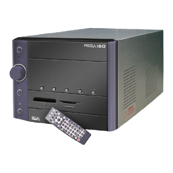
Page 14: Front Panel
Getting Started Front Panel Backward Forward Mode Play/Pause Eject/Stop Hi-Fi Power Switch Shuttle Controller PC Power Switch Card Reader (For Deluxe model) PC Reset “Front I/O Cover” Release Button Front I/O Cover (See p. 2-7 for information on front I/O.) Back Panel Mouse Parallel Port... -
Page 15: System Specification
Chapter 1 1.2 System Specification - MS-6796 (Proprietary F/F), 185 x 290 mm (6 layers) CPU: - Support Socket 462 for AMD Athlon /Duron /Athlon XP up to 3000+ ® Chipset: - nVIDIA nFORCE2 (Crush 18G) + MCP2T Memory: - DDR 333 x 2, support memory up to 2.0GB (Dual Channel support) On-Board Audio: - AC’... - Page 16 Getting Started Power Supply: - 200W (PFC 5V/12V SB) Full Range Chassis: - 202(W) x 320(D) x 151(H) mm On-Board Headers & Connectors - Rear Panel: Parallel Port x 1, VGA x 2, PS/2 x 2, Mic in/Line in/Line out x 1, USB x 2, LAN (RJ45) x 1, SPDIF/O x 1, Modem (RJ11) x 1, TV-out (S-Video) - Front Panel: Mic-in x 1, Headphone x 1, USB x 2, SPDIF/I x 1, 1394 x 1 (4-pin), 1394 x 1(6-pin)
-
Page 17: Performance Pc
Chapter 1 1.3 Performance PC When PC is power on, the MEGA180 is your performance PC. Power on means “If the power button of PC is pressed, the Hi-Fi stereo has no function even you press the Hi-Fi button.” However, you can still use the audio function through Windows Media Player and Mega Radio. - Page 18 Getting Started Target Operating System -- Microsoft Windows XP Home Edition Security -- The security features protect the data of machine from unauthorized access through BIOS control. Password -- The MEGA180 uses two levels of BIOS access (User Password & Supervisor Password) to protect the computer system.
-
Page 19: Hi-Fi Audio
Chapter 1 1.4 Hi-Fi Audio When PC is powered off, the MEGA 180 can be used as a Hi-Fi audio. You can press the Hi-Fi button or use the remote controller to start the audio function. Power-off means “When used as a Hi-Fi audio, the PC should be in power-off status. - Page 20 Getting Started MEGA 180 is equipped with SRS audio enforce- ment technology. SRS (Sound Retrieval System) was the first generation of 3D sound, dramatically improv- ing the quality of standard stereo. SRS is based on the human hearing system and was designed to retrieve...
- Page 21 Chapter 1 1-10...
-
Page 22: Chapter 2. Introducing Mainboard
Introducing Mainboard Introducing Mainboard 2.1 Mainboard Layout 2.2 CPU 2.3 Memory 2.4 Power Supply 2.5 Front Panel 2.6 Back Panel 2.7 Connectors 2.8 Jumper 2.9 Slots... -
Page 23: Mainboard Layout
Chapter 2 2.1 Mainboard layout Front I/O Connector IDE Connectors FDD Connector Front Panel Power Connector IDE1 Radio Antenna Connector IDE2 DDR DIMM Slots Color LED Connector Card Reader Connector Radio Module Mini PCI slot FSB Frequency Jumper FSB Mode Jumper SMSC LPC47M292-NR Clear CMOS Jumper... -
Page 24: Cpu
Introducing Mainboard 2.2 CPU The MEGA 180 supports AMD Athlon , Duron , Athlon XP up to ® 3000+ processors in the 462-pin package. The mainboard uses a CPU socket called Socket A for easy CPU installation. When you are installing the CPU, make sure the CPU has a heat sink and a cooling fan attached on the top to prevent overheating. -
Page 25: Cpu Installation Procedures
Chapter 2 CPU Installation Procedures Please turn off the power and Open Lever unplug the power cord before install- ing the CPU. Sliding 90 degree Plate Pull the lever sideways away from the socket. Make sure to raise the lever up to a 90-degree angle. Gold arrow Look for the gold arrow. -
Page 26: Memory
Introducing Mainboard 2.3 Memory The mainboard provides 2 slots for 184-pin DDR SDRAM DIMM (Double In-Line Memory Module) modules and supports the memory size up to 2GB. You can install PC2700/DDR333, PC2100/DDR266 or PC1600/DDR200 modules into the DDR DIMM slots (DIMM1&DIMM2). Introduction to DDR SDRAM DDR (Double Data Rate) SDRAM is similar to conventional SDRAM, but doubles the rate by... -
Page 27: Power Supply
Chapter 2 2.4 Power Supply The system is equipped with a 200W(PFC) ATX power supply. The power cord of power supply has been connected to the connector JWR1 on the mainboard when shipped out. Except the 20-pin connector JWR1, you can find another 4-pin power connector JPW1 on the mainboard. -
Page 28: Front Panel
Introducing Mainboard 2.5 Front panel The Front Panel is independent and extended from the mainboard. It’ s connected to the Front I/O Connector on the mainboard. You can find the following ports on the Front Panel. Optical SPDIF-In USB x 2 J1394-1 J1394-2 Mic-In... -
Page 29: Ieee 1394 Port: J1394-1
Chapter 2 IEEE 1394 Port: J1394-1 The bigger 6-pin IEEE 1394 Port on the back panel is designed for you to connect to IEEE 1394 devices without external power. That means the mainboard can provide the power for the devices connected to this port. Software Support IEEE 1394 Driver is provided by Windows 98 SE, Win-... -
Page 30: Mic-In/Head-Phone
Introducing Mainboard Mic-in/Head-Phone Mic-in is a connector for microphone. Head-Phone is a connector for Speakers or Headphones. OPTICAL SPDIF-in The OPTICAL connector allows you to receive the audio file of SPDIF interface for recording and playing. The SPDIF (Sony & Philips Digital Interface) is developed jointly by the Sony and Philips corporations . -
Page 31: Back Panel
Chapter 2 2.6 Back panel The Back Panel provides the following ports: Mouse Parallel Port LAN Port VGA 2 S-Video out Keyboard USB x 2 VGA 1 Lin-in Mic-in Optical SPDIF-out (Default) Speak-out VGA Port The mainboard provides two DB 15-pin VGA connectors for you to con- nect two monitors. -
Page 32: Mouse/Keyboard Connectors
Introducing Mainboard Mouse/Keyboard Connectors The mainboard provides two standard mini DIN connectors for attaching PS/2 mouse and keyboard. You can plug a PS/2 mouse or keyboard directly ® ® into the connector. Pin Definition SIGNAL DESCRIPTION Mouse DATA Mouse DATA No connection Ground Mouse Clock... -
Page 33: Usb Ports
Chapter 2 USB Ports The mainboard provides two USB2.0 EHCI/USB1.1 OHCI Universal Se- rial Bus root for attaching USB devices such as keyboard, mouse or other USB- compatible devices. You can plug the USB device directly into the connector. USB Port Description SIGNAL DESCRIPTION -Data 0... -
Page 34: Parallel Port
Introducing Mainboard Parallel Port The mainboard provides a 25-pin female centronic connector as LPT. A parallel port is a standard printer port that supports Enhanced Parallel Port (EPP) and Extended Capabilities Parallel Port (ECP) mode. Pin Definition SIGNAL DESCRIPTION STROBE Strobe DATA0 Data0 DATA1... -
Page 35: Audio Port
Chapter 2 Audio Port Speak-out is a connector for Speakers or Headphones. Line In is used for external CD player, Tape player, or other audio devices. Mic-in is a connector for microphones. These three ports can also be used for 5.1 channel audio output. -
Page 36: Connectors
Introducing Mainboard 2.7 Connectors IDE Connectors: IDE1 & IDE2 The mainboard has a 32-bit Enhanced PCI IDE and Ultra DMA 33/66/100/ 133 controller that provides PIO mode 0~4, Bus Master, and Ultra DMA/33/66/ 100/133 function. The two connectors on the mainboard allows you to connect to two IDE devices. -
Page 37: Cd-In Connector: Cn7
Chapter 2 CD-in Connector: CN7 The connector is for CD-ROM audio connector. TV-Tuner Card Connector: CN6 The mainboard provides the connector to connect the TV-Tuner card. The TV-Tuner card is included in the package. You can insert the TV-Tuner card into the PCI Slot 1. -
Page 38: Front Panel Power Connector: Jfp1
Introducing Mainboard Front Panel Power Connector: JFP1 The mainboard provides a Front Panel connector for electrical connection to the Front Panel switches and LEDs. JFP1 is compliant with Intel Front Panel ® I/O Connectivity Design Guide. Power LED JFP1 Reset Power Switch Switch... -
Page 39: Color Led Connector: Cn4
Chapter 2 Color LED Connector: CN4 The connector is used to connect the color LED on the front panel. CN 4 VCC3SBY +12VSBY SPI Bus Key (0-~5) CD_SMI VCC5 HDLED PWRBTNH FP_RST LED-BL VCC5SBY Modem Module Connector: J6 (Optional) The mainboard provides the connector to connect the modem module. The modem module is directly inserted into the connector without an extra cable. -
Page 40: Jumpers
Introducing Mainboard 2.8 Jumpers There is a CMOS RAM on board that has a power supply from external battery to keep the data of system configuration. With the CMOS RAM, the sys- tem can automatically boot OS every time it is turned on. That battery has long life time for at least 2 years. -
Page 41: Fsb Mode Jumper: J8
Chapter 2 FSB Mode Jumper: J8 This jumper allows you to set the CPU FSB mode. Safe mode User mode 100 MHz (default) 133 MHz CPU FSB Frequency Jumper: J7 This jumper is used to specify the CPU FSB (Front Side Bus) frequency. Leave the jumper short connected if a 133/166MHz FSB CPU is installed. -
Page 42: Slots
PCI Slot The PCI slot allows you to insert PCI card or TV Tuner card. The TV Tuner card is included in the MEGA 180. When adding or removing expansion cards, make sure that you unplug the power supply first. Meanwhile, read the... -
Page 43: Chapter 3. Using Audio Function
Using Audio Function Using Audio Function 3.1 Control Panel 3.2 Remote Controller 3.3 AC Power on 3.4 Playing CD/MP3 in Hi-Fi Mode 3.5 Playing FM/AM in Hi-Fi Mode 3.6 Using Audio Function in PC Mode... - Page 44 The MEGA 180 is featured with audio function. There are two ways to use audio function: in PC mode, in Hi-Fi mode. As the MEGA 180 is shipped out in barebone, you must install the necessary components (such as HDD, CPU, RAM...) before us- ing audio function in PC mode.
-
Page 45: Control Panel
Using Audio Function 3.1 Control Panel Backward Forward Mode Play/Pause Eject/Stop Hi-Fi Power Switch Shuttle Controller Deluxe model HiFi Power Start the audio function. Mode Choose the audio mode (CD/MP3, FM, AM) Eject the CD/MP3 or stop the play. In Hi-Fi Eject/Stop mode, you can press this button to recall memory sub-mode. -
Page 46: Remote Controller
Chapter 3 3.2 remote Controller The slim and subtle remote controller embeds more than 30 buttons for your quick access. In Hi-Fi mode, you can control the play and EQ mode wih one touch. Even in Media Center (PC mode), you can still fully control the miltimedia applications with the remote controller. -
Page 47: Ac Power On
Using Audio Function 3.3 AC Power ON - Plug in the power cord After plugging in the power cord. You will see the panel (Color LED) items FLASH 2 times. - Set Timer Then you can adjust time by shuttle. You will see timer 00:00 flash. -
Page 48: Playing Cd/Mp3 In Hi-Fi Mode
Chapter 3 3.4 playing CD/MP3 in Hi-fi mode - Select CD/MP3 Press HiFi button to start the audio function. Press MODE on the Control Panel to select CD/MP3 mode or press CD/MP3 on the remote controller to play CD/MP3. If there is no CD in the tray or CD is broken, the Color LED shows “NO disc”. - Page 49 Using Audio Function - Pause Music Press “Play/Pause” button to pause the music. - Play Next Song Press the “Forward” button to play the next song. - Replay the song Press “Backward” button once to re- play the song. - Replay previous song Press the “Backward”...
- Page 50 Chapter 3 - Adjusting volume Turn the shuttle clockwise to turn the volume up and counterclockwise to turn the volume down. - Set Play Sub-Mode Press the shuttle once to set the Play Sub-Mode (NORMAL, : Allows you to play the CD in normal selection. RANDOM and REPEAT DISC) : Allows you to play the CD at random.
- Page 51 Using Audio Function - Set EQ Sub-Mode : To play the CD/MP3 in Normal mode. Turn the shuttle to choose EQ Su b- Mod e. T he i tem y ou choose will flash and the others : To play the CD/MP3 in POP mode. are on.
-
Page 52: Playing Fm/Am In Hi-Fi Mode
Chapter 3 3.5 playing FM/AM in hi-fi mode - Select AM/FM Press the “MODE” utton on the Con- trol Panel to set AM/FM mode or press AM/FM button on the Remote Con- troller to switch to AM or FM station. - Next Available Station Press the “Forward”... - Page 53 Using Audio Function - Adjusting Volume Turn the shuttle to adjust the volume (3 steps). - Recall Memory Station Press the “Eject/Stop” once to recall the memory sub-mode and turn the shuttle to choose the number of spot (1-6) to play.
-
Page 54: Using Audio Function In Pc Mode
Remote Controller Function 1. Press “Hi-Fi” button to turn on/off radio. 2. Press “FM/AM” button to launch MSI Mega Radio to listen to radio. 3. Press “Mute” button to mute the volume. 4. Press “Vol up/down” button to adjust volume. -
Page 55: Cd\Mp3 Mode
Using Audio Function Front Panel Function 1. Press “Hi-Fi” button to turn on/off radio. 2. Press “Mode” button to launch MSI Radio to listen to radio. 3. Turn “Shuttle” to adjust the volume. 4. Press “Forward/Backward” button to get an available station. - Page 56 Chapter 3 Remote Controller Function 1. Press “Hi-Fi” button to turn on/off CD/MP3. 2. Press “FM/AM/CDMP3” button to select the mode you want. 3. Press “Mute” button to mute the volume. 4. Press “Vol up/down” button to adjust volume. 5. Press “Forward/Backward” button to get the next/last song. 6.
-
Page 57: Chapter 4: Setting Bios Function
Setting BIOS Function Setting BIOS Function 4.1 Entering Setup 4.2 The Main Menu 4.3 Standard CMOS Features 4.4 Advanced BIOS Features 4.5 Advanced Chipset Features 4.6 Integrated Peripherals 4.7 Power Management Setup 4.8 PnP/PCI Configurations 4.9 PC Health Status 4.10 Frequency/Voltage Control... -
Page 58: Entering Setup
Chapter 4 4.1 Entering Setup Power on the computer and the system will start POST (Power On Self Test) process. When the message below appears on the screen, press <DEL> key to enter Setup. Press DEL to enter SETUP If the message disappears before you respond and you still wish to enter Setup, restart the system by turning it OFF and On or pressing the RESET button. -
Page 59: Getting Help
Setting BIOS Function Getting Help After entering the Setup menu, the first menu you will see is the Main Menu. Main Menu The main menu lists the setup functions you can make changes to. You can use the control keys ( ↑↓ ) to select the item. The on-line description of the highlighted setup function is displayed at the bottom of the screen. -
Page 60: The Main Menu
Chapter 4 4.2 The main menu Once you enter Phoenix-Award BIOS CMOS Setup Utility, the Main Menu ® (Figure 1) will appear on the screen. The Main Menu allows you to select from twelve setup functions and two exit choices. Use arrow keys to select among the items and press <Enter>... - Page 61 Setting BIOS Function Power Management Setup Use this menu to specify your settings for power management. PnP/PCI Configurations This entry appears if your system supports PnP/PCI. PC Health Status This entry shows your PC health status. Frequency/Voltage Control Use this menu to specify your settings for frequency/voltage control. Load Fail/Safe Defaults Use this menu to load factory default settings into the BIOS for stable system performance operations.
-
Page 62: Standard Cmos Features
Chapter 4 4.3 standard cmos features The items in Standard CMOS Features Menu are divided into 14 categories. Each category includes no, one or more than one setup items. Use the arrow keys to highlight the item and then use the <PgUp> or <PgDn> keys to select the value you want in each item. - Page 63 Setting BIOS Function If you select Manual, related information is asked to be entered to the following items. Enter the information directly from the keyboard. This information should be provided in the documentation from your hard disk vendor or the system manufacturer.
-
Page 64: Advanced Bios Features
Chapter 4 4.4 advanced bios features Anti-Virus Protection The item is to set the Virus Warning feature for IDE Hard Disk boot sector protection. If the function is enabled and any attempt to write data into this area is made, BIOS will display a warning message on screen and beep. Settings: Disabled and Enabled. - Page 65 Setting BIOS Function will skip some check items. Available options: Enabled, Disabled. 1st/2nd/3rd Boot Device The items allow you to set the sequence of boot devices where BIOS attempts to load the disk operating system. Boot Other Device Setting the option to Enabled allows the system to try to boot from other device if the system fails to boot from the 1st/2nd/3rd boot device.
- Page 66 Chapter 4 Typematic Rate (Chars/Sec) After Typematic Rate Setting is enabled, this item allows you to set the rate (characters/second) at which the keys are accelerated. Settings: 6, 8, 10, 12, 15, 20, 24 and 30. Typematic Delay (Msec) This item allows you to select the delay between when the key was first pressed and when the acceleration begins.
- Page 67 Setting BIOS Function Boot OS/2 for DRAM > 64MB This allows you to run the OS/2 operating system with DRAM larger than 64MB. ® When you choose No, you cannot run the OS/2 operating system with DRAM ® larger than 64MB. But it is possible if you choose Yes. Hard Disk S.M.A.R.T.
-
Page 68: Advanced Chipset Features
Chapter 4 4.5 advanced chipset features NOTE: Change these settings only if you are familiar with the chipset. Current CPU Clock It shows the current clock frequency of the CPU. (read only) System Performance This field allows users to control the status of system performance. Users may select [Auto] for the most stable settings by SPD. - Page 69 Setting BIOS Function overclocked CPU/FSB parameters. Select [Normal] for normal mode CPU/FSB parameters. FSB/DRAM Ratio This setting controls the ratio of CPU FSB clock & DRAM Frequency to enable the CPU & DRAM to run at different frequency combinations. Please note that the setting options vary according to the CPU FSB clock preset.
- Page 70 Chapter 4 allowed to precharge. If insufficient time is allowed for the RAS to accumulate its charge before DRAM refresh, refresh may be incomplete and DRAM may fail to retain data. This item applies only when synchronous DRAM is installed in the system.
- Page 71 Setting BIOS Function System BIOS Cacheable Selecting Enabled allows caching of the system BIOS ROM at F0000h-FFFFFh, resulting in better system performance. However, if any program writes to this memory area, a system error may result. Setting options: Enabled, Disabled. Video RAM Cacheable Selecting Enabled allows caching of the video memory (RAM) at A0000h to AFFFFh, resulting in better video performance.
-
Page 72: Integrated Peripherals
Chapter 4 4.6 integrated peripherals IDE Function Setup Press <Enter> to enter the sub-menu and the following screen appears: OnChip IDE Channel 10 The integrated peripheral controller contains an IDE interface with support for the IDE channel. Choose [Enabled] to activate the channel. Settings: Enabled, Disabled. - Page 73 Setting BIOS Function Primary/Secondary Master/Slave PIO The four IDE PIO (Programmed Input/Output) fields let you set a PIO mode (0-4) for each of the four IDE devices that the onboard IDE interface supports. Modes 0 through 4 provide successively increased performance. In Auto mode, the system automatically determines the best mode for each device.
- Page 74 Chapter 4 select Enabled for automatic detection of the optimal number of block read/ writes per sector the drive can support. Settings: Enabled, Disabled. Onboard Device Press <Enter> to enter the sub-menu and the following screen appears: AC97 Audio Auto allows the mainboard to detect whether an audio device is used. If an audio device is detected, the onboard AC’...
- Page 75 Setting BIOS Function OnChip 1394 This item allows you to enable/disable the onboard IEEE1394 controller. Setting options: Auto and Disabled. OnChip Lan (nVIDIA) Setting to [Auto] allows the BIOS to auto-detect the nVIDIA LAN controller and enable it. Setting options: Auto and Disabled. MAC Address (nVIDIA) Setting to [Enabled] allows users to manually update the MAC address under MAC (NV) Address Input.
- Page 76 Chapter 4 Disabled Line Printer port 0 3BC/ I RQ 7 278/IRQ5 Line Printer port 2 378/IRQ7 Line Printer port 1 Parallel Port Mode SPP : Standard Parallel Port EPP : Enhanced Parallel Port ECP : Extended Capability Port ECP + EPP: Extended Capability Port + Enhanced Parallel Port SPP/EPP/ECP/ECP+EPP To operate the onboard parallel port as Standard Parallel Port only, choose “SPP.”...
-
Page 77: Power Management Setup
Setting BIOS Function 4.7 Power management setup Sleep State This item specifies the power saving modes for ACPI function. If your operating system supports ACPI, such as Windows 98SE, Windows ME and Windows 2000, you can choose to enter the Standby mode in S1(POS) or S3(STR) fashion through the setting of this field. - Page 78 Chapter 4 Power Management This item is used to select the degree (or type) of power saving and is related to these modes: Suspend Mode and HDD Power Down. There are three options for power management: Min Saving Minimum Power Management. Suspend Mode=1 Hour Max Saving Maximum Power Management.
- Page 79 Setting BIOS Function IRQ/Event Activity Detect Press <Enter> and the following sub-menu appears. IRQ [3-7, 9-15], IRQs Activity & IRQ8 This setting enables/disables the monitoring of the specified IRQ line. If set to Enabled, the activity of the specified IRQ line will prevent the system from enter- ing power saving modes or awaken it from power saving modes.
-
Page 80: Pnp/Pci Configurations
Chapter 4 4.8 pnp/pci configurations This section describes configuring the PCI bus system and PnP (Plug & Play) feature. PCI, or Peripheral Component Interconnect, is a system which allows I/O devices to operate at speeds nearing the speed the CPU itself uses when communicating with its special components. - Page 81 Setting BIOS Function a “Ø”). The settings are: Auto (ESCD), Manual. IRQ Resources The items are adjustable only when Resources Controlled By is set to Manual. Press <Enter> and you will enter the sub-menu of the items. IRQ Resources list IRQ 3/4/5/7/9/10/11/12/14/15 for users to set each IRQ a type depending on the type of device using the IRQ.
-
Page 82: Pc Health Status
Chapter 4 4.9 PC health status System/CPU Temperature, CPU Fan Speed, +2.5V, Vccp, +3.3V, +5V, +1.5V These items display the current status of all of the monitored hardware devices/ components such as CPU voltages, temperatures and all fans’ speeds. 4-26... -
Page 83: Frequency/Voltage Control
Setting BIOS Function 4.10 Frequency/Voltage Control AGP Clock Control This item allows users to set the AGP clock manually or by default. Options: Default, Manual. AGP Clock Value When AGP Clock Control is set to Manual, users can key in a DEC number between 66 and 120. - Page 84 Chapter 4 PCI Clock Auto Detect This feature enables the BIOS to auto detect PCI device and set PCI slot clock. NOTE: Changing CPU Ratio/Vcore could result in the instability of the system; therefore, it is NOT recommended to change the default setting for long-term usage.
- Page 85 Media Center Deluxe III Media Center Deluxe III 5.1 What is Media Center Deluxe III 5.2 Installing Media Center Deluxe III 5.3 Setting the Media Center Deluxe III 5.4 Using the Media Center Deluxe III 5.5 Using the Remote Controller 5.6 Uninstalling...
-
Page 86: What Is Media Center Deluxe Iii
PC resource, we strongly suggest that you install it on the PC running Win- dows 2000/XP to get the best performance. MSI Remind you... If you want to use the TV function in the Media Center Deluxe III, please check whether your system has equipped the op- tional TV tuner card (MS-8606). - Page 87 Media Center Deluxe III 2. Enter user’ s information and click Next to continue. 3. The Media Center Deluxe III will be installed to the default folder or your preferred one. Click Browse to point to the preferred folder. Click Next to continue.
- Page 88 Chapter 5 4. It will be installed with the default title of MSI Media Center Deluxe III. You can edit a preferred title for it. Click Next to continue. 5. The status bar shows the installation process.
- Page 89 Media Center Deluxe III 6. Click Finish to complete the Media Center Deluxe III installation.
-
Page 90: Setting The Media Center Deluxe Iii
Chapter 5 5.3 Setting the media center deluxe III Once you have installed the Media Center Deluxe III, a pop-up window appears asking you to configure your system before entering the Media Center Deluxe III. OK to skip the process, and then change these settings in the Media You can cl i ck Center Deluxe III later. - Page 91 Media Center Deluxe III 5.3.1 General Check here Check here Set here Set here Hide Date & Time You can decide whether the date & time to be displayed on the top of your Media Center Deluxe III. Enable FullScreen Control You can check here to enable the full screen control.
- Page 92 Chapter 5 5.3.2 Pictures Check here Check here Set here Set here Play in Random Order Check the box next to this option, and the pictures will be played at random when using slideshow. Include Subfolders Check the box next to this option, and those pictures in the subfolders will be played when using slideshow.
- Page 93 Media Center Deluxe III 5.3.3 Televsion Select here Select here Select here Select here Select here Select here Select here Select here TV Source You can set the TV source. Option: Cable and Antenna. Country Select the country where you are. Capture Device This item will show the video capture chipset that your tuner card is using.
- Page 94 Chapter 5 Input Source You can choose the source of video from cable TV, video device with S-Video connector or video device with Composite connector. - Source from cable TV S-Video - Source from device which supports S-Video output Composite - Source from device which supports composite output Audio Device This item will show the audio chipset that your PC is using.
- Page 95 Media Center Deluxe III 5.3.4 DVD Select here Select here Select here Select here Select here Set here Audio Language The DVD will be played in the language that you choose, if supported. Subtitle The DVD will be played with the subtitle that you choose, if supported. Auto Resume The video will be played from the position that you choose.
- Page 96 Chapter 5 5.3.5 MediaLibrary Add / Delete Path The location of the media files can be added / delected in advanced. When playing multimedia files in the Media Center Deluxe III, those files in the locations above will be used. Click ReScan, the Media Center Deluxe III will resume the content of the media library.
- Page 97 Media Center Deluxe III 5.3.7 Radio Each area has its proprietary frequency range. If you are unable to receive some stations in your area, there might be the inporper setting in this option. Check the porper radio box to correct the problem. The range for each area is listed below: Others(Europe) --- 87.5 ~ 108.0 MHz Japan --- 76.0 ~ 91.0 MHz...
-
Page 98: Using The Media Center Deluxe
Chapter 5 5.4 using the media center deluxe III Click the Media Center Deluxe III icon on the desktop, the main page of the Media Center Deluxe III will show as below: Chapter 5.4.1 Chapter 5.4.2 Chapter 5.4.3 Chapter 5.4.4 Chapter 5.4.5 Chapter 5.4.6 Chapter 5.4.7... - Page 99 Media Center Deluxe III Settings Click AutoScan, it will automatically scan all available channels for content. The number of channels available varies depending on whether you are using an an- tenna or cable TV. While it is scanning for channels, each channel will briefly appear in the display window.
- Page 100 Chapter 5 Schedule Click Schedule, you can enter the recording schedule screen. Click Add to program a once/weekly/daily recording; in addition, you can click Delete or Modify to delete or modify the existen schedule. Click here Closed Caption In some area, the TV programs come with hided caption. Click Closed Caption to show or hide the caption.
- Page 101 Media Center Deluxe III 5.4.2 Music Click Music, you can play music from your pre-programmed playlists or CD. My Location The Media Center Deluxe III will play the music files from your optical drives. View Library The Library share the same content with that of the Microsoft Media Player ®...
- Page 102 Chapter 5 5.4.3 Pictures Click View Pictures, you can view pictures from a specified folder. Click here to view the picture in full s c r e e n . P r e s s E S C k e y resume Sort by Name / Sort by Date The pictures can be sorted by name or date as you like.
- Page 103 Media Center Deluxe III Click here to view the video clip in full screen. Press E S C k e y resume 5.4.5 DVD / VCD Click DVD / VCD to watch DVD ro VCD. Settings / Start LanguageMate Please refer to chapter 5.3.4. Vocal There are left, right and both vocal for your selection.
- Page 104 Chapter 5 5.4.6 Radio Click Radio to listen to broadcasts. Sort by Name / Frequency These stations can be sorted by name or frequency as you like. AutoScan When first launch the radio player, please click AutoScan to add all available stations to your station lists.
- Page 105 Media Center Deluxe III 5.4.7 Karaoke Click Radio to listen to broadcasts. Settings / Start LanguageMate Please refer to chapter 5.3.4. Vocal There are left, right and both vocal for your selection. Sound Effect You can choose a virtual sound effect for the playing DVD / VCD. These virtual sound effects are None, Rock, Bass, Hall, Soft, Vocal, Echo and Karaoke.
- Page 106 Chapter 5 5.4.8 Application Click Application to quick launch an application. Click here to execute the application S et t i ng s Click Settings to edit the applications list. T h e l oc a t i o n o f t h e s h ort c u t s i n your s ystem T h e c u r r e n t...
- Page 107 Media Center Deluxe III 5.4.9 Setup Click Setup, the window shows step-by-step procedures guiding you to personalize your Media Center Deluxe III. Check the radio box Check the radio box Set the delay time Click here to continue Hide Date & Time You can decide whether the date &...
-
Page 108: Audio Device
Chapter 5 TV So urce You can set the TV source. Option: Cable and Antenna. Country Select the country where you are. Video Capture Device This item will show the video capture chipset that your tuner card is using. Input Source You can choose the source of video from TV cable, video device with S-Video connector or video device with Composite connector. - Page 109 Media Center Deluxe III may vary according to the hardware of your PC. Recording Quality This item allows you to set the quality of recording video. Transi tion Ti me You are allowed to set time for picture slideshow. Take the window above as an example, when you use slideshow to view pictures, the picture shifts to next one after 2 seconds.
- Page 110 Chapter 5 Click here to finish Audi o L anguage The DVD will be played in the language that you choose, if supported. Subti tl e Language The DVD will be played with the subtitle that you choose, if supported. Auto R esume The video will be played from the position that you choose.
-
Page 111: Using The Remote Controller
Media Center Deluxe III 5.5 Using the remote Controller You can use the attached remote controller to control TV as you do in the living room. Check the following note if your remote controller doesn’ t function. What if the TV Tuner Card is installed correctly... What if all necessary cables are connected... - Page 112 Chapter 5 Press the power button under operating system to launch Media Center Deluxe III or MSI PVS alone (if Media Center Deluxe III is not installed). If the MSI PVS is not installed, the power button is void. Number Key You can enter the numbers of channel directly to shift to the channel you want.
-
Page 113: Uninstall
2. Find and double-click Add or Remove Programs icon. Double-click here 3. Select the program that you want to remove. Click Change/Remove to continue. Select MSI Me- d i a C e n t e r Deluxe III and click here... - Page 114 Chapter 5 Please DO NOT REMOVE THE SHARED FILES. Always click No to continue. Click here when asking Click Finish to complete the uninstallation. 5-30...
-
Page 115: Chapter 6: Wireless Lan Card (For Deluxe Model)
Wireless LAN Card Wireless LAN Card (for Deluxe Model) 6.1 Introduction 6.2 Wireless Network Utility 6.3 Encryption 6.4 Status 6.5 Information... -
Page 116: Introduction
The data transfer rate can be auto-negotiated to 1, 2, 5.5Mbps or up to 11Mbps, and is compatible with any existing IEEE802.11b devices. With MSI Wireless LAN Card, you can roam between conference room and office without being disconnected the LAN cables; in addition, sharing files and printers can be easy tasks. -
Page 117: Hardware Specifications
Wireless LAN Card 6.1.1 Hardware Specifications Compliant Standards - IEEE802.11b Bus and Connector Types - 32-bit 3.3V Type IIIA - 124-pin Golden Finger Security Mechanism - Hardware-based WEP Privacy Operational Environment - Operational Temperature: 0~55 - Humidity: 10~90% (Non-Condensing) Weight and Dimension - Weight:12g - Dimension: 50.8 x 59.6 x 4.9mm 6.1.2 Radio Frequency Specifications... -
Page 118: Wireless Network Utility
Chapter 6 6.2 Wireless network utility After installing the driver, MSI Wireless LAN Card provides a convenient and powerful utility that allows you to set up, configure, and know your network- ing status easily and clearly. 6.2.1 The MSI Wireless LAN Icon - Not connected to the network. - Page 119 If your MSI wireless LAN adapter supports Software AP function, you can see this item in the sub-menu, and which allows you to use your MSI wireless adapter as a virtual access point. For details, refer to the MSI Software AP/Gateway User’ s Guide.
- Page 120 If you use Windows XP, the wireless LAN is controlled by the operating system (default). To take full advantage of your MSI wireless adapter, it is recom- mended to use the MSI Wireless Network Utility to control your wireless LAN.
- Page 121 3. Click Advanced, and the Properties window will appear as below. Uncheck this option Click 4. Uncheck the Use Windows to configure my wireless network settings option. Then, click OK. 5. Now, you can use MSI W ireless Network Utility to configure your network.
-
Page 122: Networking
Point must be located with the communication range of the Access Point (see the Access Point's manual for details). Connecting to the Access Point: 1. Click the MSI Wireless LAN icon to bring up the Wireless Net- work Connection window. Click... - Page 123 Wireless LAN Card If you want to configure the network settings: 1. Click Advanced in the Wireless Network Connection window. 2. The Available Networks field contains a list of available Access Points in your network. Select (highlight) one network you want, and then click Configure to set up the selected network.
- Page 124 Chapter 6 4. Click OK. The selected network will appear in the Preferred Networks field. If it contains two or more networks in the list, you can use Move up/Move down to set the priority. Click 5. Click OK to complete the configuration, and an icon indicating connected to the network will appear in the status area.
- Page 125 - All the computers connected should be set to Ad-hoc mode. - The computers have the same SSID (network name) setting. To configure the settings: 1. Click the MSI Wireless LAN icon to bring up the Wireless Network Connection window. Then, click Advanced. Click...
- Page 126 Chapter 6 2. You can build up the Ad-hoc network by clicking Add in the Preferred Networks field. Click 3. Set up the Network Name (SSID) and Network Key (if needed) for the network. Then, check the This is a computer-to-computer [ad hoc] network;...
- Page 127 Wireless LAN Card 4. The computer set up with this Ad-hoc network in step 3 is the designated administrator of the network. Any computer can access the network by selecting Connect in the Wireless Net- work Connection window. Click 5. Click OK to complete the configuration, and an icon indicating connected to the network appears in the status area.
-
Page 128: Encryption
Chapter 6 6.4 Encryption In the wireless network environment, the administrator can set up password (Network Key) to protect the network from being attacked or unauthorized access. When building the network, you can set up 4 sets of WEP keys, which can be 5 characters (10 hex-adecimal digital) or 13 characters (26 hex-adecimal digital) and specify one of them to use. -
Page 129: Status
Wireless LAN Card 6.5 Status In the Status tab, you can configure more network settings. Signal Strength: shows the received signal strength level. Link Quality: shows the measured signal level and connection status. Channel Specifies the operating radio frequency channel in Ad-hoc mode, which should be set to the same channel as the other points in the wireless network. - Page 130 Chapter 6 It is not recommended to change these settings if you are not familiar with the advanced configuration. Fragmentation Threshold You may set the length of the fragment in this field. Please note that each fragment should not be larger than the Fragmentation Threshold. RTS/CTS Threshold You may set the length threshold.
-
Page 131: Information
Wireless LAN Card 6.6 information In the Information tab, you can get some information about the manufacturer, hardware and software. 6-17... - Page 132 Chapter 6 6-18...