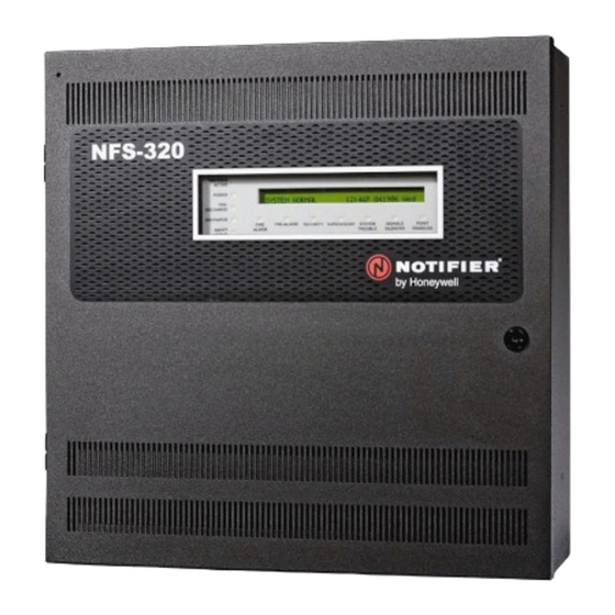
Honeywell NOTIFIER NFS-320 Document
Hide thumbs
Also See for NOTIFIER NFS-320:
- Manual (7 pages) ,
- Wiring manual (80 pages) ,
- Product installation document (18 pages)
Table of Contents
Advertisement
Quick Links
12 Clintonville Road
Northford, CT 06472-1610 USA
800-289-3473 • FAX 203-484-7118
www.notifier.com
For additional documentation on this product, visit http://notifiermanuals.com. This additional documentation for the NFS-320 may be used as a refer-
ence only.
NOTE: The term NFS-320 is used to refer to the NFS-320, NFS-320E, NFS-320C, and NFS-320SYS unless otherwise noted.
NOTE: For Mass Notification applications, Class A circuits called out in this manual are Class X.
1 Installation
Wiring methods used shall be in accordance with Standard for Installation and Classification of Burglar and Holdup Alarm Systems, UL 681.
Wiring methods used shall be in accordance with Standard for Central Station Alarm Services, UL 827.
This product is intended to be installed in accordance with the following:
•
NFPA 70 - National Electrical Code
•
NFPA 72 - National Fire Alarm Code
•
NFPA 12 - Standard on Carbon Dioxide Extinguishing Systems
•
NFPA 12A - Standard on Halon 1301 Fire Extinguishing Systems •
•
NFPA 13 - Standard for Installation of Sprinkler Systems
•
Canadian Electrical Code, Part I
•
ULC S524 - Standard for the Installation of Fire Alarm Systems •
•
NFPA 2010 - Standard for Fixed Aerosol Fire Extinguishing
System
•
NFPA 92 - Standard for Smoke-Control Systems
•
UL 2572 - Standard for Mass Notification Systems
Follow these guidelines when mounting the product's backbox:
•
Backbox should be installed in a dry, indoor location.
•
It is recommended that this system and its peripherals be installed in an environment with a normal room temperature of 15-27°C/60-80°F and at
a relative humidity of 93% ± 2% RH (non-condensing) at 32°C ± 2°C (90°F ± 3°F).
•
Locate the backbox so the top edge is 66 inches (1.6764 m) above the surface of the finished floor.
•
Access to the cabinet shall be in accordance with NFPA 90, article 110.33.
•
Allow sufficient clearance around cabinet for door to swing freely.
•
Use cables provided to connect dress panel(s) and cabinet door to earth ground.
Terminal Block/
Connector
TB4
Alarm & Trouble Output Relays -
Common
TB5
Supervisory & Security Output
Relay - Common or
programmable
TB6 thru TB9
NAC Circuits
Description
• Power-limited (Class 2) only if connected to a power-limited source
• Voltage and Current: Rated 2.0 A at 30 VDC resistive
• Non-supervised
• Power-limited (Class 2) only if connected to a power-limited source
• Voltage and Current: Rated 2.0 A at 30 VDC resistive
• Can be programmed as Alarm via VeriFire Tools
• Non-supervised
• Nominal Operating Voltage: 24 VDC Regulated
• Maximum Current: 1.5A (See Note 1)
• End-Of-Line Resistors: 2.2 K 1/2 W (ELR-2.2K)
• Wiring Configuration: Class B or Class A
• Ground Fault Impedance: 0 ohms
• Maximum Line Impedance: 20 ohms
• Supervised
• Power-limited (Class 2)
Table 1 CPU Wiring Connections (1 of 2)
NFS-320 and NFS-320SYS
Listing Document
PN 52745LD:G9 5/19/2022 16475
•
NFPA 16 - Standard for Deluge-Foam Water Systems
•
NFPA 17 - Standard for Dry Chemical Extinguishing Systems
•
NFPA 17A - Standard for Wet Chemical Extinguishing Systems
NFPA 2001 - Standard for Clean Agent Fire Extinguishing Systems
•
UL 2610 - Standard for Commercial Premises Security Alarm Units and
Systems
•
NFPA 15 - Standard for Water Spray Fixed Systems
ULC S561 - Installation and Services for Fire Signal Receiving Centers
and Systems
•
ULC-S527-11 - Standard for Control Units for Fire Alarm Systems
•
UL 864 Standard for Control Units and Accessories for Fire Alarm
Systems, 10th Edition
Specifications
Advertisement
Table of Contents

Related Manuals for Honeywell NOTIFIER NFS-320


Summary of Contents for Honeywell NOTIFIER NFS-320
- Page 1 NFS-320 and NFS-320SYS Listing Document 12 Clintonville Road PN 52745LD:G9 5/19/2022 16475 Northford, CT 06472-1610 USA 800-289-3473 • FAX 203-484-7118 www.notifier.com For additional documentation on this product, visit http://notifiermanuals.com. This additional documentation for the NFS-320 may be used as a refer- ence only.
- Page 2 Terminal Block/ Description Specifications Connector • Nominal Voltage: 24 VDC, Regulated TB10 DC Power • Maximum Current: 1.25 A DC, 1.5 A max for special applications (See Note 1) • Maximum Ripple Voltage: 176 mVrms • Class B wiring. Supervise with a power supervision relay EOLR-1 •...
- Page 3 1.1 NFS-320SYS Option Boards Slot 1 (CPU, CPS-24, and primary display) Slot 2 (CPU, CPS-24, and primary display) Slot 3 (Mounting location Keypad/display for LEM-320) or other unit attaches to option board chassis rails Slot 4 Mounting location for option boards and other compatible peripherals (Recommended mounting location for fiber versions of the...
- Page 4 When installing the Network Control Display (NCD) into the NFS-320SYS chassis, it can only be left mounted because of the position of the ground- ing screw. Backbox CPS-24/E Dress Panel Option boards Mounted on BMP-1 Figure 3 Top View of Mounting an NCD in the NFS-320SYS Chassis Annunciators, which are attached to the fire alarm control panel Figure 4 Top View of Mounting an NCD with Annunciators NOTE: See the NCD Manual #LS10210-051NF-E for more information.
- Page 5 Figure 5 Installing the CPU on the Chassis Figure 6 Installing the Power Supply on the CPU Figure 7 Installing the KDM-2 on the CPU Figure 8 Installing Option Boards on the CPU Figure 9 Installing Option Boards on the Chassis Figure 10 Installing the Chassis into the Cabinet NFS-320 and NFS-320SYS UL Listing Document —...
- Page 6 1.2 NFS-320 Option Boards The NFS-320 ships fully assembled within its cabinet. One or two option boards can be mounted inside the NFS-320 cabinet, under the keypad, as shown in Figure 12. Option boards that can be installed internally include the wire and/or fiber versions of the NCM or HS-NCM, TM-4, and UDACT/ UDACT-2.
- Page 7 LED2 LED3 LED4 LED5 LED6 LED7 LED8 LED12 LED14 LED16 LED18 LED11 LED13 LED15 LED17 NFS-320 and NFS-320SYS UL Listing Document — P/N 52745LD:G9 5/19/2022...
- Page 8 Figure 14 Power-Supply Wiring Connections NFS-320 and NFS-320SYS UL Listing Document — P/N 52745LD:G9 5/19/2022...
- Page 9 Terminal Block/ Description Specifications Connector • Voltage and current: AC Power NFS-320(SYS): 120 VAC 5.0 A NFS-320E(SYSE): 240 VAC 2.5 A • Frequency: 50/60 Hz • Wiring size: Maximum 12 AWG (3.31 mm ) with 600 VAC insulation • Supervised •...
- Page 10 NFS-320 and NFS-320SYS UL Listing Document — P/N 52745LD:G9 5/19/2022...
-
Page 11: Fire/Security Applications
UL Power-limited Wiring Requirements Power-limited (Class 2) and non-power-limited circuit wiring must remain separated in the cabinet. All power-limited circuit wiring must remain at least 0.25 inches (6.35 mm) from any non-power-limited circuit wiring. All power-limited and non-power-limited circuit wiring must enter and exit the cabinet through different knockout and or conduits. -
Page 12: General Security Requirements
(a) on an open or short circuit (b) on a ±50% change in resistance value from the End-of-Line resistor value (c) on loss of communication with the device. A tamper switch installed in the cabinet door will indicate a door tamper condition whenever the door is open. If the control panel indicates a Security alarm, you can perform acknowledge, signal silence, and system reset from the control panel. -
Page 13: Connecting An Rks-S Remote Key Switch
Connecting an RKS-S Remote Key Switch The RKS-S Remote Key Switch arms and disarms the system. It can be mounted in a UL listed single-gang electrical box. Both the monitor module and RKS-S must be mounted within the protected area. Refer to the Product Installation Document (15984) for information on how to wire the RKS-S to a FMM-1 and FMM-101 module. - Page 14 Zone Map: ZA Custom Label: Exit Door # Motion Detectors with Monitor Modules Address: LXXMYYY (arbitrary) Type ID: ACCESS MONITOR Zone Map: ZB Custom Label: Motion Detection Programming of Logic Equations Logic Equation for 1 minute exit delay: ZLa* = DEL(00:30, 00:00:00, address of key switch) Logic Equation for Trouble arming system: ZLb* = AND (ZA, address of key switch, NOT(Zla)) Logic Equation to arm system:...
-
Page 15: Security Annunciation
Security Annunciation A1P1 Mode: Monitor Source: ZLc A1P2 Mode: Monitor Source: ZLe System Status A1P3 (red is armed) Mode: Monitor System Alarm (red is alarm) Source: LXXMYY Entry/Exit Door 1 Status (red is unsecured) A1P4 Entry/Exit Door 2 Status Mode: Monitor (red is unsecured) Source: LXXMYY Additional doors can be monitored, up to the number of available annunci-... - Page 16 Typical wiring for proprietary security alarm applications with monitor modules Figure 21 shows typical wiring for proprietary security alarm applications with FMM-1 modules. Note the following: UL-listed 47K End-of-Line Resistor • The module is programmed with software Type Code. SECURITY NFS-320 Protected (provided with module) •...
-
Page 17: Earth Ground
Earth Ground To meet UL wiring requirements, install grounding straps on the backbox as shown below. Figure 23 Installing Grounding Straps 2 Operation Following are the approved applications of the NFS-320: • Local application – Emergency relocation (paging, live and pre-recorded) –... - Page 18 • Flashes the LED (red) FIRE ALARM • Displays a Type Code that indicates the type of device that activated the fire alarm • Sends an Alarm message to LCD Display, remote annunciators, History buffer, installed printers and CRT-2s. • Latches the control panel in alarm (Panel will not return to normal operation until a System Reset is completed) •...
- Page 19 Correct the condition that activated the MN Alarm. Press the key to return the control panel to normal operation. A “System Normal” message is sent to the LCD display, remote SYSTEM RESET annunciators, history buffer, installed printers, and CRT-2s. – Mass Notification Supervisory (If no other events exist on the fire panel) •...
- Page 20 • Displays in the status banner on the control panel, along with information specific to the device TROUBL • Sends a Trouble message to the LCD display, remote annunciators, history buffer, installed printers, and CRT-2s. • Sends a Trouble message to the proprietary receiver via the network, if applicable. Custom descriptor for Type of device Type of Event...
- Page 21 Custom descriptor for Status Banner Type Code this device location A C T I V E T A M P E R I N T E N S I V E C A R E U N I T E A S T E R N W I N G Z 0 0 4 0 3 : 1 9 P 0 4 1 5 1 2 1 M 1 4 7 Extended 12 character...
- Page 22 HVAC Equipment For smoke control applications, HVAC systems must have the following capabilities: – Supply outside air to a space – Return air from a space – Exhaust air from a space to the outside The SCS/SCE – The SCS-8 Smoke Control Station and the SCE-8 Smoke Control Expander can be used in conjunction with this panel to provide smoke control capabilities.
-
Page 23: Canadian Applications
• NAC Reactivation • Primary power source failure indication • DAC Communication Format – SIA – Contact ID – 4 + 2 Standard – 4 + 1 – 3 + 1 – 4 + 1 Ademco Express – 4 + 2 Ademco Express •... -
Page 24: Programming Options
4 Programming Options 1 = P R O G R A M M I N G 2 = R E A D S T A T U S E N T R Y ( E S C A P E T O A B O R T ) Menu Hierarchy ENTER PROG OR STAT PASSWORD, THEN ENTER. - Page 25 2 = Read Status READ 1 = P R O G R A M M I N G 2 = R E A D S T A T U S E N T R Y 0 = POINT ( E S C A P E T O A B O R T ) 2 = HIST (History) 4 = ALARM HIST (Alarm History) R E A D P O I N T = 0 H I S T = 2 A L A R M H I S T = 4 <...
- Page 26 NOTE: When programming points, take the following into design consideration: Each general zone must be dedicated to a single event type (i.e. Fire, MN, Security, etc.) Map inputs only to general zones designated for the input’s event type. For example, map mass notification devices to general zones designated for mass notification.
- Page 27 Detector Type Alarm (FlashScan) Alarm (CLIP) Pre-Alarm AL:1=0.50 % AL:1=0.50 % PA:1=Auto SMOKE (ION) AL:2=0.75 % AL:2=0.75 % PA:2=0.40 % (See notes AL:3=1.00 % AL:3=1.00 % PA:3=0.50 % AL:4=1.25 % AL:4=1.25 % PA:4=0.75 % AL:5=1.50 % AL:5=1.50 % PA:5=1.00 % AL:6=1.75 % (d) AL:6=1.75 % (d) PA:6=1.25 % (d)
- Page 28 SUP.L(DUCTI) supervisory lights supervisory LED Ionization smoke detector used as a duct detector to report supervisory condition rather than alarm. Latching. 1, 2 SUP.T(ION) supervisory lights supervisory LED Ionization smoke detector used to report supervisory condition rather than alarm. Tracking. SUP.L(ION) supervisory lights supervisory LED...
- Page 29 SUP.L(LASER) supervisory lights supervisory LED Laser smoke detector used to report supervisory condition rather than alarm. Latching. SUP.T(LASER) supervisory lights supervisory LED Laser smoke detector used to report supervisory condition rather than alarm. Tracking. SMOKE(DUCTL) fire alarm lights fire alarm LED and activates CBE Duct Laser smoke detector SUP T(DUCTL) supervisory...
- Page 30 Blinking Type Code selection 20-character user-editable custom label. P R O G R A M M O N I T O R W E S T E R N E N T R A N C E A N D H A L L W A Y 0 9 _ _ _ _ _ _ _ _ 1 M 1 0 1...
- Page 31 ESC/MN trouble Indicates Trouble on a Mass Notification Monitors mass notification devices. Will generate a trouble TROUBLE MON device condition for both open and short conditions. ECS/MN MNS alarm Does not light any LEDs, overrides existing Monitors mass notification devices MONITOR fire event, shuts off silenceable outputs and all fire activated strobes and activates CBE.
- Page 32 TROUBLE PEND Control Module, an XPC-8 circuit, or an XP5-C (in NAC mode) that will activate upon receipt of a trouble condition, and remain in the ON state until all troubles have been ACKNOWLEDGED. It is programmed as “switch inhibit”. MNS GENERAL Mass notification supervised output.
-
Page 33: Testing/Maintenance
5 Testing/Maintenance When finished with the original installation and all modifications, conduct a complete operational test on the entire installation to verify compliance with applicable NFPA standards. Testing should be conducted by a factory-trained fire alarm technician in the presence of a representative of the Authority Having Jurisdiction and the owner’s representative. - Page 34 • Remove AC power, activate an Initiating Device Circuit through an alarm initiating device or an addressable initiating device on the SLC, and check that programmed active notification appliances sound, and alarm indicators illuminate. Measure the battery voltage with notification appliances active.
- Page 35 Advanced Walk Test During Advanced Walk Test, when the tester activates an input, all CBE mapped to that input will activate with the exception of releasing functions. Each input activation is latching; that is, it will not deactivate until the system is reset. Advanced Walk Test will sound all activated outputs, overriding a setting of “...
-
Page 36: Notifier Compatible Equipment
Sealed lead-acid batteries must be replaced within at most 5 years from their date of manufacture. Minimal replacement battery capacity appears on the control panel marking label. Immediately replace a leaking or damaged battery. You can get replacement batteries from the manufacturer. WARNING: SULFURIC ACID BATTERIES CONTAIN SULFURIC ACID WHICH CAN CAUSE SEVERE BURNS TO THE SKIN AND EYES AND DAMAGE TO FABRICS. -
Page 37: System Configuration
CAB-4 Series Doors (Black unless “R” is added to the P/N. Add “B” to the P/N TR-A4 A-sized trim ring for blank door) TR-B4 B-sized trim ring DR-A4 A-sized door, 1 row of equipment TR-C4 C-sized trim ring DR-B4 B-sized door, 2 rows of equipment TR-D4 D-sized trim ring DR-C4 C-sized door, 3 rows of equipment CHS-4L Low-Profile Chassis... - Page 38 Process Module Description Local P (PPU) P(Burg) P Rec Mana. CAB-A4 Enclosure Y(4) (5) Y(4) (5) Y(4) (5) Y(4) (5) Y(4) (5) Y(4) (5) Y(4) (5) Y(4) (5) Y(4) (5) CAB-B4 Enclosure Y(4) (5) Y(4) (5) Y(4) (5) Y(4) (5) Y(4) (5) Y(4) (5) Y(4) (5) Y(4) (5) Y(4) (5) CAB-C4 Enclosure Y(4) (5) Y(4) (5) Y(4) (5) Y(4) (5) Y(4) (5) Y(4) (5) Y(4) (5) Y(4) (5) Y(4) (5)
-
Page 39: System Power/Size
Process Module Description Local P (PPU) P(Burg) P Rec Mana. KEY: Y - Yes N - No O - Optional NOTES: The system must contain either one of the two displays. The system must contain at least one of the units. Also required when devices for Carbon Monoxide signaling are employed. - Page 40 NFS-320 and NFS-320SYS UL Listing Document — P/N 52745LD:G9 5/19/2022...
- Page 41 NFS-320/E/C and NFS-320SYS/E OPERATING INSTRUCTIONS Discharge. Red LED lights when any of the releasing zones are Section 1 Operating Information active and in the process of discharging a releasing agent; turns off Normal Standby Operation. when no releasing zones are discharging a releasing agent. Green P indicator lit steadily.