Table of Contents
Advertisement
Quick Links
Advertisement
Table of Contents

Related Manuals for Omron NC1-510000


Summary of Contents for Omron NC1-510000
- Page 1 AMR Controller User's Guide NC1-510000 NC1-510001 AMR Controller I650-E-01...
- Page 2 Every precaution has been taken in the preparation of this manual. Nevertheless, OMRON assumes no responsibility for errors or omissions. Neither is any liability assumed for damages resulting from the use of the information contained in this publica- tion.
-
Page 3: Intended Audience
• Personnel in charge of managing Factory Automation systems and facilities. Applicable Products This manual covers following AMR Controller products: Product Model • AMR Controller NC1-510000 • NC1-510001 Additional Information Refer to 1-4 Product Configuration on page 1-5 for configuration details. AMR Controller User's Guide (I650) - Page 4 Introduction AMR Controller User's Guide (I650)
-
Page 5: Sections In This Manual
Sections in this Manual Sections in this Manual Overview System Configurations Hardware Specifications Installation Operating Procedures Maintenance Appendices AMR Controller User's Guide (I650) -
Page 6: Table Of Contents
CONTENTS CONTENTS Introduction ......................1 Intended Audience............................1 Applicable Products ............................1 Sections in this Manual ................... 3 Manual Information....................8 Page Structure..............................8 Special Information ............................9 Terms and Conditions Agreement................ 10 Warranty, Limitations of Liability ........................10 Application Considerations ..........................11 Disclaimers ..............................12 Safety Precautions.................... - Page 7 CONTENTS Section 1 Overview Intended Use .........................1-2 Hardware Features.........................1-3 ID Information Label ......................1-4 Product Configuration......................1-5 Section 2 System Configurations Configuration for a Mobile Robot..................2-2 Section 3 Hardware Layers and Components .......................3-3 3-1-1 Cooling Layer ..........................3-4 3-1-2 Base Layer ..........................3-4 3-1-3 Mobile Robot Layer ........................3-6 LED Indicators Base Layer ....................3-7 3-2-1...
- Page 8 CONTENTS 3-10-6 USB Type-A to USB Type-B Cables ..................3-26 3-10-7 Power Supply ..........................3-27 3-10-8 UPS ............................3-27 Section 4 Specifications General Specifications ......................4-2 4-1-1 Dimensions and Weight ......................4-2 4-1-2 General Electrical Specifications....................4-3 4-1-3 Power Consumption Specifications.....................4-4 4-1-4 Power Supply Specifications .......................4-5 4-1-5 CPU Specifications ........................4-6 4-1-6...
- Page 9 CONTENTS Initial Power ON ........................5-37 5-6-1 Initial Power ON Procedure.......................5-37 Install Software ........................5-39 Connect UPS ........................5-40 5-8-1 Connect UPS Using the USB Connector ..................5-41 5-8-2 Connect UPS Using the I/O Connector ..................5-43 Create Backup and Repair Data ..................5-46 Section 6 Operating Procedures Power ON..........................6-2 6-1-1...
-
Page 10: Manual Information
Manual Information Manual Information This section provides information about this manual. Page Structure The following page structure is used in this manual. 5 Installation Unpack This section provides details on how to unpack the Industrial Panel PC. 5-1-1 Unpack Procedure Check the package for damage. -
Page 11: Special Information
Manual Information Special Information Special information in this manual is classified as follows: Precautions for Safe Use Precautions on what to do and what not to do to ensure safe usage of the product. Precautions for Correct Use Precautions on what to do and what not to do to ensure proper operation and performance. Additional Information Additional information to read as required. -
Page 12: Terms And Conditions Agreement
Omron’s exclusive warranty is that the Products will be free from defects in materials and workmanship for a period of twelve months from the date of sale by Omron (or such other period expressed in writing by Omron). Omron disclaims all other warranties, express or implied. -
Page 13: Application Considerations
ANY WAY CONNECTED WITH THE PRODUCTS, WHETHER SUCH CLAIM IS BASED IN CONTRACT, WARRANTY, NEGLIGENCE OR STRICT LIABILITY. Further, in no event shall liability of Omron Companies exceed the individual price of the Product on which liability is asserted. Application Considerations... -
Page 14: Disclaimers
Disclaimers Performance Data Data presented in Omron Company websites, catalogs and other materials is provided as a guide for the user in determining suitability and does not constitute a warranty. It may represent the result of Omron’s test conditions, and the user must correlate it to actual application requirements. Actual performance is subject to the Omron’s Warranty and Limitations of Liability. -
Page 15: Safety Precautions
Safety Precautions Safety Precautions Definition of Precautionary Information The following notation is used in this manual to provide precautions required to ensure safe usage of the AMR Controller. The safety precautions that are provided are extremely important to safety. Always read and heed the information provided in all safety precautions. The following notation is used. -
Page 16: Warnings
Safety Precautions Warnings WARNING Disassembly and Dropping Do not attempt to disassemble, repair, or modify the product in any way. Doing so may result in malfunction or fire. Installation Always connect to a ground of 100 Ω or less when installing the product. Ensure that installation and post-installation checks of the product are performed by per- sonnel in charge who possess a thorough understanding of the machinery to be instal- led. - Page 17 Safety Precautions Actual Operation Security setting adjustments should only be performed by the engineer in charge that possesses a thorough understanding of the security settings. Selecting non-recommend- ed security settings can put your system at risk. Changing BIOS information is only allowed for the engineer in charge that possesses a thorough understanding of the BIOS settings because it can change the behavior of the product.
-
Page 18: Cautions
Safety Precautions Cautions CAUTION Wiring The product has an internal non-isolated DC power supply. Circuit ground (0 VDC) and frame ground are connected together. When connecting a non-isolated device or a non- isolated interface to the product, take appropriate actions to avoid communication fail- ures or damage to the mentioned ports. -
Page 19: Precautions For Safe Use
Precautions for Safe Use Precautions for Safe Use Disassembly, Dropping, Mounting, Installation and Storage • Do not drop the product or subject it to abnormal vibration or shock. Doing so may result in product malfunction or burning. • When unpacking, check carefully for any external scratches or other damages. Also, shake the product gently and check for any abnormal sound. - Page 20 • If this product caused radio interference with an RFID premises radio station, immediately change the product's frequency or stop radio emission, and contact OMRON representative for actions to take to prevent cross talk.
-
Page 21: Power Supply Design And Turning On/Off The Power Supply
• Use an Omron S8BA UPS with the correct revision number to prevent improper system shutdown. • Power ON after connecting the product and an external monitor. -
Page 22: Operation
• Correctly perform wiring and setting, and ensure that the shutdown by the UPS can be executed. • Always use the SMART monitoring feature for storage devices that do not comply to the Omron Storage Device Specifications. Monitor the operating temperature and vibrations to ensure they stay within the environmental specifications of the storage device. -
Page 23: Precautions For Correct Use
OS boot failure or crash. • Ensure the selected operating system supports ACPI to enable operating system shutdown using the power button. • Download the enhanced Video Driver from the OMRON Download Center and install it on the Indus- trial PC. Wiring •... -
Page 24: Actual Operation And Operation
Precautions for Correct Use • Do not weld the conductors. Doing so may cause the wires to break with vibration. Actual Operation and Operation • After an OS update or a peripheral device driver update for the product is executed, the product be- havior might be different. -
Page 25: Regulations And Standards
• EMC Directive EMC Directive OMRON devices that comply with EU Directives also conform to the related EMC standards so that they can be more easily built into other devices or the overall machine. The actual products have been checked for conformity to EMC standards. -
Page 26: Conformance To Ul And Csa Standards
If the product is used in a manner not specified in the Instruction Sheet or in the product manuals then the protection provided by the equipment may be impaired. Software Licenses and Copyrights This product incorporates certain third party software. The license and copyright information associat- ed with this software is available at http://www.fa.omron.co.jp/nj_info_e/. AMR Controller User's Guide (I650) -
Page 27: Related Manuals
Related Manuals Related Manuals The following manuals are related. Use these manuals for reference. Related AMR Controller Manual Model Cat. Manual name num- Application Description bers NY-series Op- W616 Learning all software related informa- An introduction to the AMR Con- erating Sys- tion about the AMR Controller. -
Page 28: Terminology And Abbreviations
Term / Abbreviation Description Industrial PC Platform An integrated range of OMRON products designed for use in any industrial applica- tion that will benefit from advanced PC technology Industrial Monitor An industrial monitor with a touchscreen as the user interface designed to work in... -
Page 29: Software
Terminology and Abbreviations Software Term / Abbreviation Description ACPI Advanced Configuration and Power Interface protocol for operating systems Application Programming Interface BIOS Basic Input Output System. The first software run by a PC when powered on. Developer Any person involved with the development of software Daylight Saving Time Enhanced Write Filter FBWF... -
Page 30: Revision History
Revision History Revision History A manual revision code appears as a suffix to the catalog number on the front and back covers of the manual. I650-E-01 Cat. No. Revision code Revision code Date Revised content May 2020 Original production AMR Controller User's Guide (I650) - Page 31 Overview This section provides general information about the AMR Controller. Intended Use ....................1-2 Hardware Features ..................1-3 ID Information Label..................1-4 Product Configuration ................... 1-5 AMR Controller User's Guide (I650)
-
Page 32: Overview
1 Overview Intended Use The Autonomous Mobile Robot (AMR) Controller is designed to be integrated as top controller in an HD-1500 Mobile Robot. The AMR Controller simultaneously uses a custom Linux operating system and programs as well as third-party software to serve as a powerful PC platform. AMR Controller User's Guide (I650) -
Page 33: Hardware Features
1 Overview Hardware Features The AMR Controller provides the following hardware features: • Compact design for mounting in a Mobile Robot The AMR Controller can be mounted with two types of brackets. • Fanless cooling and a powerful CPU The AMR Controller has passive cooling for the CPU which means no moving parts and less main- tenance effort. -
Page 34: Id Information Label
The name of your product Model and configuration details Model Power rating Power rating details Standards and QR The applicable standards and a QR code for OMRON internal use code LOT number and Production details, consisting of: • serial number The lot number of the AMR Controller in the format DDMYY£. -
Page 35: Product Configuration
1 Overview Product Configuration This section provides an overview of the product configurations available for the Box PC with AMR Controller. The product configuration is visible in the model-ID that is mentioned on the ID information label of the product. The structure of the model-ID is: NC1-££££££. The ID consists of 3 sets of digits. - Page 36 1 Overview AMR Controller User's Guide (I650)
-
Page 37: System Configurations
System Configurations This section provides an overview of the system configurations for the AMR Controller. Configuration for a Mobile Robot ..............2-2 AMR Controller User's Guide (I650) -
Page 38: Configuration For A Mobile Robot
2 System Configurations Configuration for a Mobile Robot The Box PC with AMR Controller supports the following hardware configurations. Ports Ethernet NC1-series IPC Audio base layer mobile robot layer Operating System & Expansion Mobile Robot Software Utilities & Support APIs SD Memory COMM Card... - Page 39 Hardware This section provides an overview of the hardware of the AMR Controller. Layers and Components ................3-3 3-1-1 Cooling Layer ....................3-4 3-1-2 Base Layer ...................... 3-4 3-1-3 Mobile Robot Layer ..................3-6 LED Indicators Base Layer................3-7 3-2-1 PWR LED Indicator ..................
- Page 40 3 Hardware 3-10 Optional Hardware ..................3-24 3-10-1 Mounting Brackets..................3-24 3-10-2 SD Memory Cards..................3-24 3-10-3 USB Flash Drives ..................3-25 3-10-4 CFast Cards ....................3-25 3-10-5 DVI Cables ....................3-26 3-10-6 USB Type-A to USB Type-B Cables.............. 3-26 3-10-7 Power Supply ....................
-
Page 41: Layers And Components
3 Hardware Layers and Components This section shows the layers of the AMR Controller. Item Name Description Cooling layer Layer to cool the base layer Depending on the product configuration fans can be present and the thick- ness can vary. Base layer The layer with the CPU and the main interfaces The connector layout and the installed option board depend on the product... -
Page 42: Cooling Layer
3 Hardware 3-1-1 Cooling Layer This section gives details on the cooling layer. The cooling layer will dissipate excessive heat from the AMR Controller. Thickness and design details of the cooling layer can vary, depending on the product configuration. Cooling layer with pas- A thin cooling layer for passive sive cooling and a cooling... - Page 43 3 Hardware Item Name Description USB 2.0 connectors 2 USB 2.0 interface connectors 10BASE-T / 100BASE-TX / 3 RJ45 Gb Ethernet interface connectors 1000BASE-T Ethernet con- nectors DVI connector Digital Visual Interface connector SD Memory Card slot SD Memory Card slot Option port Wireless interface CFast Card slot...
-
Page 44: Mobile Robot Layer
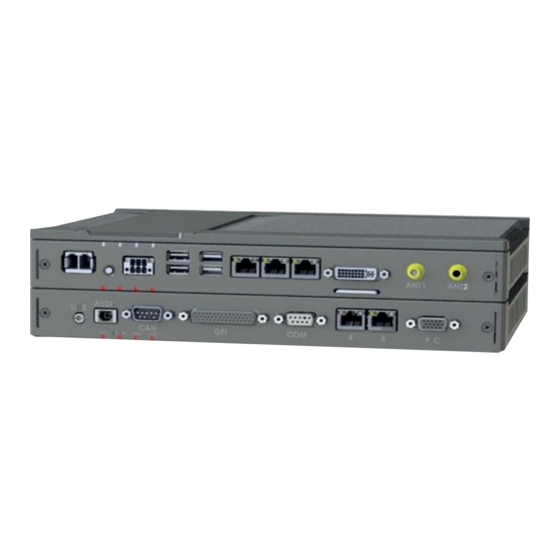
3 Hardware 3-1-3 Mobile Robot Layer This section shows the component names and functions for the Mobile Robot layer. The Mobile Robot layer houses the functionality that is typical for the Box PC with AMR Controller. Frontside Backside The connector layout and the available components can differ depending on the product configuration. Item Name Description... -
Page 45: Led Indicators Base Layer
3 Hardware LED Indicators Base Layer The AMR Controller has LED indicators located at the base layer. These LED indicators provide the current operating status of the AMR Controller. The following LED indicators are available: Item Name Description Indicator Power Indicates the operating mode of the AMR Controller. -
Page 46: Err Led Indicator
3 Hardware 3-2-2 ERR LED Indicator The Error LED (ERR) indicates the presence and type of an error within the AMR Controller. Color Status Meaning • Not lit The 24 VDC power is not supplied • No error is present •... -
Page 47: Led Indicators Mobile Robot Layer
3 Hardware LED Indicators Mobile Robot Layer The AMR Controller has LED indicators located at the mobile robot layer. These LED indicators pro- vide the current operating status of the AMR Controller. The following LED indicators are available: Item Name Description Indicator MCU status... -
Page 48: Io Led Indicator
3 Hardware 3-3-2 IO LED Indicator The Input Output LED (IO) indicates the presence and type of an error within the AMR Controller. Color Status Meaning Not lit No IO error An IO error is active Additional Information • The status of this LED can also be defined by users using the Industrial PC System API. •... -
Page 49: Power Button
3 Hardware Power Button The power button is located at the base layer. The power button is used to manually switch the AMR Controller ON and OFF. Additional Information • Refer to 6-1 Power ON on page 6-2 for ON details. •... -
Page 50: Sd Memory Card Slot
3 Hardware SD Memory Card Slot The SD Memory Card slot is located at the base layer. The SD Memory Card slot on the AMR Controller accepts SD Memory Cards with the following specifi- cations. • SDHC type (SD 2.0 specification) •... -
Page 51: Cfast Card Slot
3 Hardware CFast Card Slot A CFast Card slot is located at the rear side of the base layer. The CFast Card slot accepts CFast Cards that comply with the CFast 2.0 specification. Additional Information Refer to 3-10-4 CFast Cards on page 3-25 for details. 3-13 AMR Controller User's Guide (I650) -
Page 52: Connectors Base Layer
3 Hardware Connectors Base Layer This section gives an overview of the connectors located at the base layer of the AMR Controller. 3-7-1 Power Connector The power connector on the AMR Controller is used to supply 24 VDC power to the AMR Controller. The power connector is supplied with the AMR Controller. -
Page 53: Usb Connectors
3 Hardware Additional Information • Refer to 4-2-2 I/O Connector Specifications on page 4-12 for specifications. • Refer to 5-4-4 Wire the I/O Connector on page 5-31 for wiring details. • Refer to 5-5 Connect on page 5-34 for connection details. 3-7-3 USB Connectors Two USB connectors support USB 2.0 and two USB connectors support USB 3.0 specifications. -
Page 54: Ethernet Connectors
3 Hardware 3-7-4 Ethernet Connectors The Ethernet connectors provide 3 individual Ethernet ports on the AMR Controller. Each port offers 10BASE-T/100BASE-TX/1000BASE-T Ethernet speeds. Additional Information • Refer to 4-2-4 Ethernet Connector Specifications on page 4-17 for specifications. • Refer to 5-5 Connect on page 5-34 for connection details. 3-7-5 DVI Connector The DVI interfaces supported on this connector are dependent on the configuration of the AMR Con-... -
Page 55: Wifi Connectors
3 Hardware 3-7-6 WiFi Connectors The WiFi interface is located at the base layer. The WiFi interface on the AMR Controller provides 2 connectors for antennas or coax-cables. Additional Information • Refer to 4-2-6 Wireless Interface Specifications on page 4-21 for details. •... -
Page 56: Connectors Mobile Robot Layer
3 Hardware Connectors Mobile Robot Layer This section gives an overview of the connectors located at the mobile robot layer of the AMR Control- ler. 3-8-1 Line Connector The line connector is located at the mobile robot layer. This connector supports analog audio. Additional Information •... -
Page 57: Audio Connector
3 Hardware 3-8-2 Audio Connector The optical audio connector is located at the mobile robot layer. The connector supports digital audio using an optical fiber. This connector is also known as Toslink even though the official name is EIAJ optical. Additional Information •... -
Page 58: Expansion Connector
3 Hardware 3-8-4 Expansion Connector The Expansion interface is located at the mobile robot layer. The Expansion interface contains additional interfaces for the COMM connector and the CAN connec- tor and supports digital outputs. The Expansion interface supports RS232, RS422 and CAN interfaces and 24V digital outputs. -
Page 59: Ethernet Connectors
3 Hardware 3-8-6 Ethernet Connectors The Ethernet connector on the Mobile Robot Layer provides two Ethernets port with 10BASE-T/ 100BASE-T/1000BASE-T Ethernet speeds. Additional Information • Refer to 4-2-4 Ethernet Connector Specifications on page 4-17 for specifications. • Refer to 5-5 Connect on page 5-34 for connection details. 3-21 AMR Controller User's Guide (I650) -
Page 60: Plc Safety I/O Connector
3 Hardware 3-8-7 PLC Safety I/O Connector The PLC connector for the Safety I/O interface is located at the mobile robot layer. The Safety I/O interface on the AMR Controller provides the interface to a Safety PLC. Additional Information • Refer to 4-2-12 PLC Connector Specifications on page 4-29 for details. •... -
Page 61: Spare Parts
The Accessory Kit can contain accessories that are not applicable to your model. 3-9-2 Connectors Details for the recommended connectors are provided below. OMRON is not responsible for the operation or performance of any other connector. Model Appearance Specifications NY000-AK01 Power Connectors for Omron Industrial PCs. -
Page 62: 3-10 Optional Hardware
Refer to 4-1-8 Bracket Specifications on page 4-8 for bracket dimension details. 3-10-2 SD Memory Cards SD Memory Card details are provided below. OMRON is not responsible for the operation, performance or write life of any other brand of SD Memo- ry Card. Model Appearance... -
Page 63: Usb Flash Drives
3 Hardware 3-10-3 USB Flash Drives USB Flash Drive details are provided below. OMRON is not responsible for the operation, performance, or write life of any other brand of USB Flash Drives. Model Appearance Capacity FZ-MEM2G 2 GB FZ-MEM8G 8 GB... -
Page 64: Dvi Cables
90 mm 3-10-6 USB Type-A to USB Type-B Cables USB Type-A to USB Type-B cable details are provided below. OMRON is not responsible for the operation or performance of any other brand of USB Type-A to USB Type-B cable. Model Appearance... -
Page 65: Power Supply
3 Hardware 3-10-7 Power Supply Details for the recommended power supply are provided below. OMRON is not responsible for the operation or performance of any other power supply. Model Appearance Specifications S8VK-G£££24 Output voltage: 24 VDC S8VK-X£££24A-EIP S8VK-S£££24 S8VK-WA£££24 Additional Information •... - Page 66 • Refer to 4-1-3 Power Consumption Specifications on page 4-4 for power consumption de- tails. • Refer to the OMRON website for S8BA specifications or to the UPS S8BA User's Manual (Cat. No. U702) for the UPS manual. Note that the power consumption details determine the output current/capacity of your UPS.
-
Page 67: Specifications
Specifications This section provides specifications of the AMR Controller. General Specifications ................. 4-2 4-1-1 Dimensions and Weight .................. 4-2 4-1-2 General Electrical Specifications..............4-3 4-1-3 Power Consumption Specifications..............4-4 4-1-4 Power Supply Specifications ................4-5 4-1-5 CPU Specifications..................4-6 4-1-6 Memory Specifications .................. -
Page 68: General Specifications
Specifications Model details Mount details Width X Height Z Weight *1 *2 Model ID Depth Y • • NC1-510000 With Mobile Ro- Not mounted 282 mm 200 mm 73 mm 3.0 kg • NC1-510001 bot layer Book mount 211 mm 3.3 kg... -
Page 69: General Electrical Specifications
4 Specifications 4-1-2 General Electrical Specifications The following table provides the general electrical specifications. Item Specifications Rated power supply voltage 24 VDC Allowable power supply voltage range 20.4 to 28.8 VDC Power supply standard SELV Grounding method Ground to less than 100 Ω Inrush current At 24 VDC: 12 A / 6 ms max. -
Page 70: Power Consumption Specifications
57 W Installed drives Drives Power consumption CFast Refer to 4-1-7 Storage Device Specifications on page 4-7 for Omron drive de- tails. For other drives refer to the applicable specifications for maximum power con- sumption details. Connected expansions Expansions Power consumption Refer to the power consumption specifications of your connected USB devices. -
Page 71: Power Supply Specifications
Controller. Refer to 4-1-3 Power Consumption Specifications on page 4-4 for details. Minimum power requirements Model Power supply • 120 W NC1-510000 • 120 W NC1-510001 Refer to 3-10-7 Power Supply on page 3-27 for power supply products. AMR Controller User's Guide (I650) -
Page 72: Cpu Specifications
4 Specifications 4-1-5 CPU Specifications This section gives the specifications of the CPUs that are available for the AMR Controller. ® ™ NY£35 Intel Core i5-7300U CPU Specifications ® ™ CPU specifications for an Intel Core i5-7300U CPU. Item Specifications Cores / Threads 2 / 4 CPU base frequency... -
Page 73: Storage Device Specifications
4 Specifications 4-1-7 Storage Device Specifications This section provides the specifications of the storage devices. CFast Card Specifications Specifications for the CFast Drive are provided in the table below. Model Specifications Item 64 GB NY000-AT03 Model Type pSLC Max. power consumption 0.9 W Max. -
Page 74: Bracket Specifications
4 Specifications 4-1-8 Bracket Specifications The metal mounting brackets mount your AMR Controller and they are the connection for the function- al ground. Custom AMR Controller Brackets A custom AMR Controller mounting bracket can mount your AMR Controller. Dimensions of the mounting holes locations for the custom AMR Controller bracket. Bracket Details Drill Specifications Product Dimensions... - Page 75 4 Specifications Book Mount Brackets The metal mounting brackets mount your AMR Controller. Dimensions Examples of book mount brackets Additional Information • Refer to 3-10-1 Mounting Brackets on page 3-24 for bracket IDs. • Refer to 5-3-8 Book Mount Procedure on page 5-18 for book mount details. Bracket Details Drill Specifications Product Dimensions...
- Page 76 4 Specifications Wall Mount Brackets The metal mounting brackets mount your AMR Controller. Dimensions Appearance of wall mount brackets Additional Information • Refer to 3-10-1 Mounting Brackets on page 3-24 for bracket IDs. • Refer to 5-3-9 Wall Mount Procedure on page 5-19 for wall mount details. Bracket Details Drill Specifications Product Dimensions...
-
Page 77: Connector Specifications
4 Specifications Connector Specifications This section provides the Connector Specifications of the AMR Controller. 4-2-1 Power Connector Specifications The power supply connector is locked when inserted to prevent unintentional disconnection. The connector can only be inserted the correct way. The connector is a Phoenix Contact type SPC5/2-STCL-7.62 BK (1711708). The AMR Controller provides protection against reverse polarity. -
Page 78: I/O Connector Specifications
4 Specifications Locking and Removing the Power Connector The power connector automatically locks into place when the black part of the connector is held and pushed in. Pushing both orange sliders B towards the end of the connector A will release the lock when remov- ing the connector. - Page 79 4 Specifications I/O Connector Pin Details The pin details of the I/O connector. The pin layout represents the I/O connector on the AMR Controller. The I/O signals connected must be powered from a power supply which conforms to the SELV stand- ards.
- Page 80 4 Specifications I/O Connector Power Status Output Details This section provides details of the Power Status Output relay. The Power Status Output is a relay between pin 1 and 2 of the I/O Connector. Power ON Power Status Output Operation This section provides power ON details of the Power Status Output operation.
- Page 81 4 Specifications Product ON Shutdown Shutdown Product OFF start finished Closed (ON) Relay Open (OFF) Power supply removed Closed (ON) Relay Open (OFF) Additional Information Refer to 5-4-4 Wire the I/O Connector on page 5-31 for I/O connector wiring details. Lock and Remove the I/O Connector The I/O connector locks into place when the black part of the connector is held and pushed in.
-
Page 82: Usb Connector Specifications
4 Specifications 4-2-3 USB Connector Specifications The AMR Controller includes four USB connectors. Two connectors provide version 2.0 performance and two connectors provide version 3.0 performance. Details of the USB interface connectors are pro- vided below. The connector layout represents the USB connectors on the AMR Controller. Interface Connector Details per Connector •... -
Page 83: Ethernet Connector Specifications
4 Specifications 4-2-4 Ethernet Connector Specifications Details of the RJ45 Ethernet connectors are provided below. The Ethernet connector locks automatically to prevent unintentional disconnection. Base layer: 3 RJ45 connectors Mobile Robot layer: 2 RJ45 connectors The set of 3 RJ45 Ethernet connectors is available on the base layer of all models. Ethernet Connector Specification Details Details of the RJ45 Ethernet connectors are provided below. - Page 84 4 Specifications Ethernet Connector LED Indicators Base Layer Details of the RJ45 Ethernet connectors in the base layer are provided below. Each connector has LED indicators that display the link, activity and speed status. Item Indicator Color Status Description Link/Act Yellow Not lit No link...
- Page 85 4 Specifications Ethernet Connector LED Indicators Mobile Robot Layer Details of the RJ45 Ethernet connectors in the mobile robot layer are provided below. Each connector has LED indicators that display the activity and link status. Item Indicator Color Status Description Activity Yellow Not lit...
-
Page 86: Dvi Connector Specifications
4 Specifications 4-2-5 DVI Connector Specifications DVI is the standard video interface for the AMR Controller. Additional Information • Refer to 4-1-5 CPU Specifications on page 4-6 for graphics controller details. • Refer to 5-4-2 Ground on page 5-20 for grounding details. •... -
Page 87: Wireless Interface Specifications
4 Specifications 4-2-6 Wireless Interface Specifications The AMR Controller has a bluetooth interface and a WiFi interface. WiFi specifications: Item Specification Standard TX/RX Streams 2x2 Bands 2.4 GHz, 5 GHz WiFi 802.11a/b/g/n/ac Connectors 2 x RP-SMA connector for antennas or antenna ca- bles. -
Page 88: Line Analog Audio Connector Specifications
4 Specifications 4-2-7 LINE Analog Audio Connector Specifications The AMR Controller includes analog audio. Details of the analog audio interface connectors are pro- vided below. The connector layout represents the connectors on the AMR Controller. Item Specifications Connector type 3.5mm audio jack 4-pole Wiring details TRRS (Tip Ring Ring Sleeve) •... -
Page 89: Audio Optical Audio Connector Specifications
4 Specifications 4-2-8 AUDIO Optical Audio Connector Specifications The AMR Controller includes optical audio. Details of the optical audio interface connector are provid- ed below. The connector layout represents the connectors on the AMR Controller. Item Specifications Connector type TOSLINK Audio type S/PDIF digital audio Additional Information... -
Page 90: Can Connector Specifications
4 Specifications 4-2-9 CAN Connector Specifications Specifications of the CAN interface on the Mobile Robot layer of the AMR Controller. The CAN connector supports the CAN interface: Additional Information • Refer to 5-4-2 Ground on page 5-20 for grounding details. •... -
Page 91: Expansion Connector Specifications
4 Specifications 4-2-10 EXPANSION Connector Specifications Specifications of the EXPANSION interface on the Mobile Robot layer of the AMR Controller. The Expansion connector supports: • 4 interfaces RS232 This is an expansion of the COMM connector. Refer to 4-2-11 COMM Connector Specifications on page 4-27 for details. •... - Page 92 4 Specifications UL rating: Item Specifications Digital Output 24 VDC, 0.05 A/point (Resistive), 4 points 24 VDC, 1.2 VA/point (Pilot Duty), 4 points CAN Output 12 VDC, 0.1 A/point (Resistive), 1 point 4-26 AMR Controller User's Guide (I650)
-
Page 93: Comm Connector Specifications
4 Specifications 4-2-11 COMM Connector Specifications Specifications of the COMM interface on the Mobile Robot layer of the AMR Controller. The COMM connector supports: • 1 interface RS232 • 1 interface RS422 Additional Information • Refer to 5-4-2 Ground on page 5-20 for grounding details. •... - Page 94 4 Specifications Item Specifications Slew rate 6 V/us typical Powerdown Supported Data control signals Not supported (RTS, CTS, DSR, DCD, DTR) 4-28 AMR Controller User's Guide (I650)
-
Page 95: Plc Connector Specifications
4 Specifications 4-2-12 PLC Connector Specifications Specifications of the PLC interface on the Mobile Robot layer of the AMR Controller. The PLC inter- face provides 24V inputs and 24V outputs to connect to a Safety PLC. Additional Information • Refer to 5-4-2 Ground on page 5-20 for grounding details. •... - Page 96 4 Specifications Item Specifications Input OFF current 1 mA max. Input OFF voltage 5 VDC max. Input ON current 3 mA min. Input ON voltage 15 VDC min. Isolation method Not isolated 4-30 AMR Controller User's Guide (I650)
-
Page 97: Environmental Specifications
4 Specifications Environmental Specifications This section provides environmental specifications of the AMR Controller. 4-3-1 Operation Environment Specifications The following table provides the general environmental specifications for the AMR Controller. Item Specifications Ambient operating temperature 0 to 55°C Ambient storage temperature -20 to 70°C Ambient operating humidity 10% to 90% with no condensation... -
Page 98: Temperature And Humidity Specifications
4 Specifications 4-3-2 Temperature and Humidity Specifications The allowed ambient operating temperature and ambient humidity depend on the model and storage device type. • Refer to 4-3 Environmental Specifications on page 4-31 for humidity details. • Refer to the following topic for temperature details. NC1-51000£... -
Page 99: Installation
Installation This section provides all installation details for the AMR Controller. The AMR Controller can only be used in an HD-1500 Mobile Robot. Unpack ......................5-2 5-1-1 Unpack Procedure................... 5-2 5-1-2 Items Supplied....................5-2 Install Options ....................5-5 Mount....................... 5-6 5-3-1 Installation Method in Control Panels.............. -
Page 100: Unpack
5 Installation Unpack This section provides details on how to unpack the AMR Controller. 5-1-1 Unpack Procedure Check the package for damage. If there is any visible damage: • Take photos of the package and save them. • Inform your supplier immediately. Open the package. - Page 101 5 Installation Items Supplied with the AMR Controller This section describes the items supplied with your AMR Controller. • Industrial Box PC • Documentation: • Safety Precautions sheets (English and Japanese) • General Compliance Information and Instructions for EU • Standards and Certifications sheet •...
- Page 102 5 Installation Items Supplied with the Brackets This section describes the items supplied with the brackets for your AMR Controller. Additional Information • Refer to 3-10-1 Mounting Brackets on page 3-24 for bracket details. • Refer to 5-3-8 Book Mount Procedure on page 5-18 for book mount installation. •...
-
Page 103: Install Options
5 Installation Install Options This section describes the installable options for the AMR Controller. Not Applicable The AMR Controller does not have installable options. AMR Controller User's Guide (I650) -
Page 104: Mount
5 Installation Mount This section describes how to mount the AMR Controller in either a book or wall orientation inside a control panel. WARNING Ensure that installation and post-installation checks of the product are performed by personnel in charge who possess a thorough understanding of the machinery to be installed. -
Page 105: Product Orientation
5 Installation 5-3-2 Product Orientation The AMR Controller can be mounted in a book A or wall B C orientation. • For book mount there is one allowed orientation A . • For wall mount there are two allowed orientations, horizontally mounted B and vertically mounted C . -
Page 106: Temperature
Allow space to accommodate for the bending radius of the cables. • Refer to 3-10 Optional Hardware on page 3-24 for cable bending requirements of cables ad- vised by Omron. • Refer to the cable specifications of the supplier for all other cables. - Page 107 5 Installation • Wall Mount in landscape A or portrait B orientation Item Minimum distance 50 mm 100 mm 50 mm Measure the minimum distances X and Y at the air openings in the sides of the AMR Controller. Check the required bending radius of all wires for the actual required minimum distance. AMR Controller User's Guide (I650)
- Page 108 AMR Controller. • Do not install the AMR Controller directly above any heat-generating equipment, such as heaters or transformers. • Do not install the AMR Controller in a location exposed to direct sunlight. OMRON product OMRON product Natural Cooling ...
-
Page 109: Humidity
5 Installation OMRON product OMRON product Forced Air Circulation Room Cooling Cool the entire room where the control panel is located. Cooler Control panel Room Cooling Low Temperatures The AMR Controller may not start normally if the temperature is below 0°C when the power is turned ON. -
Page 110: Atmosphere
Installation Location Install the AMR Controller as far away as possible from high-voltage (600 V or higher) and power devi- ces to ensure safe operation and maintenance. Example of Recommended Equipment Arrangement OMRON product Control panel Control panel High-voltage... - Page 111 • Keep the wiring between the transformer and the AMR Controller as short as possible, twist the wires well, and keep the wiring separate from high-voltage and power lines. Power circuits Power supply for general operations circuits I/O power supply for Omron product I/O power supply for Omron product Noise Unit power supply for Omron product...
- Page 112 5 Installation Wire External I/O Signal Lines Observe the following points when wiring the external I/O signal lines. • To absorb reverse electromotive force when an inductive load is connected to an output signal, con- nect a surge suppressor near the inductive load in an AC circuit, or connect a diode near the induc- tive load in a DC circuit.
- Page 113 5 Installation External Wiring Wiring, and noise countermeasures in particular, are based on experience, and it is necessary to closely manage wiring based on experience and information in the manuals. Wiring Routes Each of the following combinations includes different signal types, properties, or levels. They will cause the signal-to-noise ratio to drop due to factors such as electrical induction.
- Page 114 Ground of 200 mm 100 Ω or less Example: Separating an OMRON product from Power Lines Wiring Ducts Whenever possible, route the cables and wires through wiring ducts. Install the wiring ducts so that it is easy to route the wires from the AMR Controller directly into the duct.
- Page 115 5 Installation Product Duct Other Precautions Basic I/O Units have both plus and minus commons, so pay attention to the polarity when wiring. 5-17 AMR Controller User's Guide (I650)
-
Page 116: Book Mount Procedure
5 Installation 5-3-8 Book Mount Procedure Use the following procedure to mount the AMR Controller in the book orientation. Additional Information • Refer to 5-4-2 Ground on page 5-20 for grounding details. • Refer to 3-10-1 Mounting Brackets on page 3-24 for the bracket model. To mount the AMR Controller: The AMR Controller has on one side light grey circles around the threaded mounting holes. -
Page 117: Wall Mount Procedure
5 Installation 5-3-9 Wall Mount Procedure Use the following procedure to mount the AMR Controller in the wall orientation. Additional Information • Refer to 5-4-2 Ground on page 5-20 for grounding details. • Refer to 3-10-1 Mounting Brackets on page 3-24 for the bracket model. To mount the AMR Controller: Mount the Brackets A to the AMR Controller C with the 6 Phillips screws B supplied with the brackets. -
Page 118: Wire
5 Installation Wire This section describes how to wire the AMR Controller. 5-4-1 Wiring Warnings and Cautions This section describes the Warnings and Cautions when wiring the AMR Controller. WARNING Provide safety measures in external circuits to ensure safety in the system if an ab- normality occurs due to malfunction of the product or due to other external factors af- fecting operation. - Page 119 5 Installation CAUTION The product has an internal non-isolated DC power supply. Circuit ground (0 VDC) and frame ground are connected together. When connecting a non-isolated device or a non-isolated interface to the product, take appropriate actions to avoid communica- tion failures or damage to the mentioned ports.
- Page 120 5 Installation Considerations for Earthing Methods Local potential fluctuations due to lightning or noise occurred by power devices will cause potential fluctuations between ground terminals of devices. This potential fluctuation may result in device mal- function or damage. To prevent this, it is necessary to suppress the occurrence of a difference in elec- trical potential between ground terminals of devices.
- Page 121 5 Installation Equipotential Bonding System Equipotential bonding is an earthing method in which steel frames and building structures, metal ducts and pipes, and metal structures in floors are connected together and make connections to the earth trunk line to achieve a uniform potential everywhere across the entire building. We recommend this earthing method.
- Page 122 5 Installation Star Earthing If the earthing method used for the building is not equipotential bonding or the earthing system is un- known, choose (a) from among the earthing methods given below. a. Connecting devices and noise sources to separate earth electrodes This is an earthing method to separately ground an earth electrode of the device that is connected with a communications cable or other devices and an earth electrode of a high-power device that could be a noise source, such as a motor or inverter.
- Page 123 5 Installation Daisy Chain This is an earthing method to connect the device that is connected with a communications cable, other devices, and a device that could be a noise source using a daisy-chain topology to a common earth electrode. This earthing method is not recommended because the device that could be a noise source may inter- fere electromagnetically with other devices.
- Page 124 5 Installation Ground Connection Details This section provides details about the ground connection. Use the functional ground terminal on the mounting bracket(s) to ground your AMR Controller. The washers and nut C are supplied with the bracket(s). Refer to Items Supplied with the Brackets on page 5-4 for details. Custom Mount The AMR Controller has on one side light grey circles around the threaded mounting holes.
-
Page 125: Wire The Power Connector
5 Installation Mount the ground connection wire B to the functional ground terminal A using the washers and nut C . Tighten the nut with a torque of 1.2 N·m max. Refer to 5-3-9 Wall Mount Procedure on page 5-19 for wall mounting details. ... - Page 126 5 Installation Additional Information • The selected conductor size must match with the used maximum power supply capacity or an overcurrent protection device must be used. • The used wires and the overcurrent protection device must meet the applicable national standards.
- Page 127 Maximum AWG according to UL/cUL • Power Supply Connector DC Power Supply The OMRON S8VK-series power supply is recommended for use with the AMR Controller. Additional Information • Refer to 3-10-7 Power Supply on page 3-27 for more information. • Refer to 4-1-3 Power Consumption Specifications on page 4-4 for power consumption details.
- Page 128 5 Installation Power Connector Wiring Procedure Use the following procedure to wire the power connector. Ensure the power connector is not connected to the AMR Controller. 7 mm Remove the sheath from the power supply wires. Precautions for Safe Use Observe the following precautions to prevent broken wires.
-
Page 129: Wire The I/O Connector
5 Installation 5-4-4 Wire the I/O Connector This section describes how to wire the I/O connector. I/O Connector Wiring Materials Use the supplied I/O connector to connect the inputs and outputs to the AMR Controller. Recommended I/O conductor sizes for the connector are provided in the table. Wire type Conductor cross-section Solid conductor... - Page 130 5 Installation Description Internal Circuit Details Power ON Input The Power ON Input and the UPS Mode Input are bi-directional and isolated. Each input can be wired as sinking (NPN) or sourc- ing (PNP). Wire these according to the output device connected to UPS Mode Input the inputs.
- Page 131 5 Installation I/O Connector Wiring Procedure Use the following procedure to wire the I/O connector. Ensure the I/O connector is not connected to the AMR Controller. 7 mm Remove the sheath from the wires. Precautions for Safe Use Observe the following precautions to prevent broken wires. •...
-
Page 132: Connect
5 Installation Connect This section describes how to connect the AMR Controller. 5-5-1 Connector Identification An overview of the connectors is available in the overview of Layers. Refer to 3-1-2 Base Layer on page 3-4 for connector details. Refer to for connector details. 5-34 AMR Controller User's Guide (I650) -
Page 133: Connection Procedure
Additional Information • Refer to 5-3 Mount on page 5-6 for mounting details. • Refer to 3-10 Optional Hardware on page 3-24 for the cables advised by Omron. Refer to individual cable specifications for cable bending requirements and connector clear- ance. - Page 134 5 Installation Connect the I/O connector. Hold the black part A when inserting the connector, this enables the auto-locking mechanism. Do not tilt the orange levers B because this will unlock the connector. Connect an external monitor such as the Industrial Monitor. Connect the monitor to the DVI connector and tighten the fastening screws.
-
Page 135: Initial Power On
Connect a keyboard and/or a mouse. Additional Information • If using an OMRON Industrial Monitor this may not be required because it has touch function- ality. • Do not connect additional storage devices before the installation of the operating system completed. - Page 136 The AMR Controller is ON and if an operating system is installed it will start. Precautions for Safe Use Always use the SMART monitoring feature for storage devices that do not comply to the Omron Storage Device Specifications. Monitor the operating temperature and vibrations to ensure they stay within the environmental specifications of the storage device.
-
Page 137: Install Software
5 Installation Install Software Install applicable software and activate Windows. Additional Information Refer to NY-series Operating Systems and Software Utilities Manual (Cat. No. W616) for de- tails. 5-39 AMR Controller User's Guide (I650) -
Page 138: Connect Ups
AMR Controller can shutdown normally without data loss. The AMR Controller can automatically start up again when the power is restored. To connect the AMR Controller to the OMRON S8BA UPS use one of the following two options: • The USB connector and Power Attendant Lite Utility Software. -
Page 139: Connect Ups Using The Usb Connector
• Drivers for the S8BA UPS from this OMRON website. • Installation files and manual for the Power Attendant Lite Utility from this OMRON website. • Installation files and manual for the UPS Settings Utility (Windows only) from this OMRON web- site. - Page 140 5 Installation UPS (S8BA) 24 VDC Power Supply (S8VK) Output Industrial PC Input AC (L) 24 VDC AC (N) 0 VDC Refer to the UPS S8BA User's Manual (Cat. No. U702) for details. Refer to 5-4-3 Wire the Power Connector on page 5-27 for wiring details. Supply power to the Power Supply.
-
Page 141: Connect Ups Using The I/O Connector
• For all other AMR Controllers following software can be downloaded: • Drivers for the S8BA UPS from this OMRON website. • Installation files and manual for the UPS Settings Utility (Windows only) from this OMRON web- site. Precautions for Safe Use •... - Page 142 5 Installation 4) Connect the Contact port of the S8BA UPS to the I/O port of the AMR Controller with the connection cable S8BW-02. Power Supply (S8VK) UPS (S8BA) Output 24 VDC IPC Product 24 VDC 0 VDC Input UPS Mode Input AC (L) 24 VDC AC (N)
- Page 143 5 Installation Additional Information The default Input sensitivity setting is Standard voltage sensitivity and this is correct. Do not set this parameter to Low voltage sensitivity. Doing so can cause a system malfunc- tion when switching to battery mode. 5-45 AMR Controller User's Guide (I650)
-
Page 144: Create Backup And Repair Data
5 Installation Create Backup and Repair Data Ensure the operating system, software and data can always be restored when required. There are different software tools to create a backup and repair data. Select the Backup and Repair procedure or procedures that are most suitable for your situation. Precautions for Correct Use Refer to NY-series Operating Systems and Software Utilities Manual (Cat. - Page 145 Operating Procedures This section provides the operating procedures for the AMR Controller. Power ON ......................6-2 6-1-1 Power ON Using the Power Button ..............6-2 6-1-2 Power ON Using the Power ON/OFF Input............. 6-2 6-1-3 Auto Power ON ....................6-2 Power OFF ......................
-
Page 146: Power On
6 Operating Procedures Power ON This section provides Power ON details. 6-1-1 Power ON Using the Power Button Start condition: Power is supplied to the AMR Controller and the AMR Controller is OFF. Press the power button and release within 1 second. Refer to 3-4 Power Button on page 3-11 for the power button location. -
Page 147: Power Off
6 Operating Procedures Power OFF This section provides Power OFF details. Before following power OFF procedures below, check that the AMR Controller is ON by examining the LED indicators on the AMR Controller. 6-2-1 Power OFF Using the Power Button Ensure all programs are closed. -
Page 148: Power Off Using The Power On/Off Input
6 Operating Procedures 6-2-2 Power OFF Using the Power ON/OFF Input Ensure all programs are closed. If required, close all active programs. Supply a 24 VDC signal to the Power ON/OFF Input (pins 3 and 4) of the I/O connector. The input signal must remain ON for a minimum of 60 ms and a maximum of 750 ms to be correctly detected by the AMR Controller. - Page 149 Maintenance This section provides an overview of all maintenance tasks for the AMR Controller. Preventive Maintenance ................7-2 7-1-1 Preventive Maintenance Schedule..............7-2 7-1-2 Clean the AMR Controller ................7-3 Corrective Maintenance................. 7-4 7-2-1 Warning and Error Messages................7-4 7-2-2 Replace the CFast Card..................
-
Page 150: Preventive Maintenance
7 Maintenance Preventive Maintenance Preventive Maintenance covers all actions that prevent downtime. 7-1-1 Preventive Maintenance Schedule Prevent unscheduled downtime with the following preventive maintenance schedule. Daily Reference • Check AMR Controller status Refer to 7-2-1 Warning and Error Messages on page 7-4 for AMR Controller Messages. -
Page 151: Clean The Amr Controller
7 Maintenance 7-1-2 Clean the AMR Controller Clean the AMR Controller periodically in order to keep it in the best operating condition. Wipe the AMR Controller with a dry, soft cloth. Precautions for Safe Use Do not use corrosive substances to clean the product. Doing so may result in the failure or malfunction. -
Page 152: Corrective Maintenance
WARNING Do not attempt to disassemble, repair, or modify the product in any way. Doing so may result in malfunction or fire. Contact your local OMRON representative if the corrective maintenance actions did not solve the problem. 7-2-1 Warning and Error Messages Warning and Error messages are provided by the AMR Controller when there is a potential problem that may cause downtime. - Page 153 7 Maintenance Windows Action Center The Windows Action Center provides information on Windows related warnings and errors. The Windows Action Center indicates security and maintenance issues. Some examples: • Virus protection (Important) Windows did not find anti-virus software on this computer. •...
-
Page 154: Replace The Cfast Card
7 Maintenance 7-2-2 Replace the CFast Card Use the following procedure to replace the CFast Card. Prepare the new CFast Card. Additional Information • Refer to 3-10-4 CFast Cards on page 3-25 for the available CFast Card models. • Refer to CFast Card Specifications on page 4-7 for specification details. To replace the CFast Card: Power OFF the AMR Controller. - Page 155 7 Maintenance Insert the replacement CFast Card A into the slot of the AMR Controller. Ensure the CFast Card A is completely in the AMR Controller with an extra push using the CFast Card slot cover. If the CFast Card can not go in completely then the CFast Card orientation is incorrect. Re- move the CFast Card, turn it upside down and reinsert it.
- Page 156 7 Maintenance AMR Controller User's Guide (I650)
- Page 157 Appendices BIOS ....................... A-2 A-1-1 BIOS Overview....................A-2 A-1-2 BIOS for 7 generation CPUs................. A-4 DVI Connector Pin Details ................A-20 A-2-1 DVI-I Connector Pin Details ................A-20 CAN Connector Pin Details ................ A-22 EXPANSION Connector Pin Details ............A-23 COMM Connector Pin Details..............
-
Page 158: A-1 Bios
Appendices A-1 BIOS This section provides the BIOS information of the AMR Controller. WARNING Changing BIOS information is only allowed for the engineer in charge that possesses a thorough understanding of the BIOS settings because it can change the behavior of the product. - Page 159 Appendices • Boot • Save & Exit BIOS Navigation and Function Keys The right part of the BIOS screens is divided in two parts. Top part. Provides additional information on selected screens or parameters. Bottom part. Provides information on Keys. •...
-
Page 160: Bios For 7 Th Generation Cpus
Appendices A-1-2 BIOS for 7 generation CPUs The BIOS settings for 7 generation CPUs. Refer to the CPU information in 1-4 Product Configuration on page 1-5 for generation details. The BIOS is divided in the pages Main, Advanced, Chipset, Security, Boot and Save&Exit. BIOS - Main The main setup screen gives platform information about the BIOS, Board Information, Firmware Revi- sion, MAC Addresses and information about the number of Boots and the Running Time. - Page 161 Appendices BIOS - Advanced This section provides Advanced BIOS information for 7 generation CPUs. Changeable BIOS Advanced parameters and their factory default values: Item Default / Remark Intel RC ACPI Settings PTID Support Disabled PECI Access Method Direct I/O Native PCI Express Support Enabled Native ASPM Disabled...
- Page 162 Appendices Item Default / Remark Power & Performance CPU - Power Manage- Boot performance mode Max Non-Turbo Per- ment Control formance Intel ® SpeedStep ™ Enabled Race To Halt (RTH) Enabled Intel ® Speed Shift Technology Enabled HDC Control Enabled Enabled Turbo Mode CPU - Power Management Control /View/Configure Turbo Options...
- Page 163 Appendices Item Default / Remark Power & Performance GT - Power Manage- Maximum GT frequency Default Max Frequen- ment Control PCH-FW Configuration Comms Hub Support Disabled JHI Support Disabled Core Bios Done Message Enabled Firmware Update Con- Me FW Image Re-Flash Disabled figuration PTT Configuration...
- Page 164 Appendices Item Default / Remark Platform Settings UCSI Retry Workaround Disabled Firmware Configuration Test PS2 Keyboard and Mouse Enabled Pmic Vcc IO Level Disabled Pmic Vddq Level Disabled SLP_SO# VM Disabled Power Sharing Manager Disabled Wireless device Disabled Enable Wireless Charge Support Disabled Enable FFU support Disabled...
- Page 165 Appendices Item Default / Remark UEFI Network Stack UEFI Network Stack Disabled CSM & Option ROM CSM Support Enabled Control Gate A20 Active Upon Request Option ROM Messages Force BIOS INT19 Trap Response Immediate Boot Option Filter UEFI and Legacy PXE Option ROM Launch Policy UEFI ROM Only Storage Option ROM Launch Policy...
- Page 166 Appendices BIOS - Chipset This section provides Chipset information for 7 generation CPUs. Changeable BIOS Chipset parameters and their factory default values: Item Default / Remark Processor Memory Configuration / Memory Thermal Configuration Refer to Memory Ther- (Integrated mal Configuration on Components) page A-15 for details.
- Page 167 Appendices Item Default / Remark Processor Memory Configuration / Memory Training Algorithms (Integrated Write Voltage Centering 2D Enabled Components) Read Voltage Centering 2D Enabled Late Command Training Enabled Round Trip Latency Enabled Turn Around Timing Training Enabled Rank Margin Tool Disabled Memory test Disabled...
- Page 168 Appendices Item Default / Remark Processor Memory Configuration Force Single Rank Disabled (Integrated Memory Remap Enabled Components) Time Measure Disabled DLL Weak Lock Support Enabled Pwr Down Idle Timer Mrc Fast Boot Enabled Lpddr Mem WL Set Set B EV Loader Disabled EV Loader Delay Enabled...
- Page 169 Appendices Item Default / Remark Platform Controller Isolate SMBus Segments Always Hub (PCH) PCI Express Configu- PCI Express Clock Gating Disabled ration Legacy IO Low Latency Disabled DMI Link ASPM PCH Side Disabled Port8xh Decode Disabled Peer Memory Write Enable Disabled Compliance Test Mode Disabled...
- Page 170 Appendices Item Default / Remark Platform Controller SATA And RST Con- Hot Plug Disabled Hub (PCH) figuration Spin Up Device Disabled SATA Device Type Hard Disk Drive Topology Unknown SATA Port 2 DevSlp Disabled DITO Configuration Disabled USB Configuration XHCI Disable Compliance Mode False xDCI Support Disabled...
- Page 171 Appendices BIOS - Chipset Details This section provides BIOS Chipset details for 6 generation and 7 generation CPUs. Memory Thermal Configuration Provides BIOS Chipset details for the submenu Processor / Memory Configuration / Memory Ther- mal Configuration /. Changeable BIOS Memory Thermal Configuration parameters and their factory default values: Item Default / Remark Memory Power and...
- Page 172 Appendices PCI Express Port Provides BIOS Chipset details for the submenu Platform Controller Hub / PCI Express Configura- tion / PCI Express Port. Changeable BIOS PCI Express Port parameters and their factory default values: Item Default / Remark PCI Express Port Enabled Topology CPU specific...
- Page 173 Appendices BIOS - Security Provides security information like BIOS Password and HDD information. WARNING Security setting adjustments should only be performed by the engineer in charge that possesses a thorough understanding of the security settings. Selecting non-recom- mended security settings can put your system at risk. Changeable BIOS Security parameters and their factory default values: Item Default / Remark...
- Page 174 Appendices BIOS - Boot Provides Boot information and configuration settings. Changeable BIOS Boot parameters and their factory default values: Item Default / Remark Quiet Boot Disabled Setup Prompt Timeout Bootup NumLock State Turn ON Power Loss Control AT Shutdown Mode Hot S5 Enter Setup If No Boot Device Enable Popup Boot Menu...
- Page 175 Appendices BIOS - Save & Exit Provides the possibility to leave the BIOS with or without saving changes and to create or restore a set of User Defaults. Save & Exit Parameters: • Save Changes and Exit Changed settings are saved and the Operating System starts with the changed settings. •...
-
Page 176: A-2 Dvi Connector Pin Details
Appendices A-2 DVI Connector Pin Details This section provides the pin details for the DVI-I connector and for the optional DVI-D connector. A-2-1 DVI-I Connector Pin Details Pin details of the DVI-I connector. C1 C2 C3 C4 The pin layout represents the DVI-I connector on the AMR Controller. Pin numbers increase from left to right for every row. - Page 177 Appendices Signal Name Function TMDS clock+ Digital clock+ TMDS clock− Digital clock− Analog red Analog red Analog green Analog green Analog blue Analog blue Analog horizontal sync Analog horizontal sync 0 VDC 0 VDC A-21 AMR Controller User's Guide (I650)
-
Page 178: A-3 Can Connector Pin Details
Appendices A-3 CAN Connector Pin Details Pin details of the CAN connector. The pin layout represents the CAN connector on the Mobile Robot layer of the AMR Controller. Signal Name Function Not connected CANL Not connected CANH Not connected +12 V For CAN peripheral A-22 AMR Controller User's Guide (I650) -
Page 179: A-4 Expansion Connector Pin Details
Appendices A-4 EXPANSION Connector Pin Details Pin details of the EXPANSION connector. The pin layout represents EXPANSION connector on the Mobile Robot Layer of the AMR Controller. Pin numbers increase from left to right for every row. Signal Name Function RS422_3_RXP RS422_3_RXN RS422_3_TXN... - Page 180 Appendices Signal Name Function Digital Output_0 Digital Output_1 Digital Output_2 Digital Output_3 RS232_5_RX RS232_5_TX RS232_4_RX RS232_4_TX RS232_3_RX RS232_3_TX RS232_2_RX RS232_2_TX A-24 AMR Controller User's Guide (I650)
-
Page 181: A-5 Comm Connector Pin Details
Appendices A-5 COMM Connector Pin Details Pin details of the COMM connector. The pin layout represents the female DB9 COMM connector on the Mobile Robot layer of the AMR Controller. Signal Name Function RS422_1_RXP RS422_1_RXN RS422_1_TXP RS422_1_TXN RS232_1_RX RS232_1_TX A-25 AMR Controller User's Guide (I650) -
Page 182: A-6 Plc Connector Pin Details
Appendices A-6 PLC Connector Pin Details Pin details of the PLC connector. The pin layout represents the PLC connector on the Mobile Robot layer of the AMR Controller. Signal Name Connects to SIO_IN0 Safety output terminal So0 of NX-SOD400 IOG terminal of NX-SOD400 IOG terminal of Safety PLC SIO_OUTTEST0 Test output terminal T0 of NX-SID800... - Page 183 Index AMR Controller User's Guide (I650)
- Page 184 Index Index Accessory kit ..............3-23 EIAJ connector ............... 3-19 Analog audio connectors Electrical Specifications ..............4-22 Specifications ..............4-3 Audio connector ..............3-19 Err LED ................3-8 Ethernet connector ............3-21 Ethernet connectors ............3-16 LED indicators ........... 4-18, 4-19 Backup ................5-46 Link indicator ...............4-19 Base layer .................3-4 Link/Act indicator ............4-18 Battery low ................3-8...
- Page 185 Index Wall mount ..............3-24 Wall mounting ..............5-19 PLC connector ..............3-22 Watchdog error ..............3-8 Specifications ..............4-29 Weights ................4-2 WiFi ................3-17 Power button ..............3-11 Power connector .............3-14 Specifications ..............4-21 Specifications .............. 4-11 Wire ................5-20 Wiring ..............5-27, 5-30 Wiring Power OFF ...............
- Page 186 Index AMR Controller User's Guide (I650)
- Page 188 4225 Hacienda Drive, Pleasanton, CA 94588 OMRON ASIA PACIFIC PTE. LTD. U.S.A. No. 438A Alexandra Road # 05-05/08 (Lobby 2), © OMRON Corporation 2020 All Rights Reserved. OMRON (CHINA) CO., LTD. Alexandra Technopark, In the interest of product improvement, Room 2211, Bank of China Tower, Singapore 119967 specifications are subject to change without notice.