Furuno FAR-3210 Operator's Manual
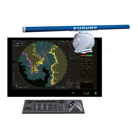
Chart radar
Hide thumbs
Also See for FAR-3210:
- Operator's manual (463 pages) ,
- Installation manual (245 pages) ,
- Instruction manual (99 pages)
Advertisement
Quick Links
CHART RADAR
English
Model
Complies with IEC62923-1/2
Radar Controls
BRILL
Rotate: Adjusts the
brilliance of the monitor.
Push: Selects a color
palette.
A/C RAIN
Rotate: Suppresses rain clutter.
Push: Toggles between manual
and automatic rain clutter
adjustment.
Rotary control for EBL
Adjusts the active EBL.
EBL1, EBL2
Activates or deactivates the respective EBL.
ALARM ACK
Acknowledges alerts; silences the
audio alarm.
See the next page.
InstantAccess knob
Rotate: Selects the buttons on the
InstantAccess bar
TM
.
Push: Activates functions of the
TM
buttons on the InstantAccess bar
.
ESC
Goes back one step in current
operating sequence on the
TM
InstantAccess bar
.
(Product Name: MARINE RADAR)
FAR-3210/3220/3220-NXT/3230S/3230S-SSD/3310/3320/
3320-NXT/3330S/3330S-SSD/3320W/3330SW/3210-BB/3220-BB/
3220-NXT-BB/3230S-BB/3230S-SSD-BB/3220W-BB/3230SW-BB
GAIN
Adjusts the
sensitivity of the
radar receiver.
A/C SEA
Rotate: Suppresses sea clutter.
Push: Toggles between manual
and automatic sea clutter
adjustment.
UNDO
Undoes edit or text input
when creating a radar
map, route, user chart.
RANGE
Selects radar range (radar
and chart radar modes),
chart scale (chart mode).
Operator's Guide
Rotary control for VRM
VRM1, VRM2
Activates or deactivates the respective VRM.
Status LED
The color and state of the LED change
according to system or alert status.
VIEW/HIDE
Radar mode, chart radar mode:
Shows or hides AZ box, Drop mark
boxes, Mark box, PI line box, Trial
box.
Chart mode: Shows or hides EBLs,
InstantAccess bar
TM
, [Overlay/NAV
Tools] box, [Route information] box,
VRMs.
1 1 1
This guide provides the basic operating
procedures for this equipment. For detailed
information, see the Operator's Manual.
The brand and product names mentioned in
this guide are trademarks, registered
trademarks or service marks of their
respective holders.
Adjusts the diameter of the active VRM.
Power switch
Turns the system on or off.
(This switch does control
monitor on/off.)
USB port (under cover)
For connection of a USB flash memory.
To use the USB port, connect the processor
unit to the USB port at the rear side of the
control unit, using the optional USB cable.
Trackball module
Operates similar to a PC mouse.
ACQ/ACT
TT: Acquires cursor-selected target, for target
tracking.
AIS: Activates cursor-selected sleeping AIS
target.
TARGET DATA
Displays the detailed data for selected TT, AIS
target, in the TT/AIS information box.
TARGET CANCEL
TT: Stops tracking cursor-selected tracked
target.
AIS: Sleeps cursor-selected activated AIS target.
Long-press to erase all displayed TT target data.
Advertisement

Related Manuals for Furuno FAR-3210


Summary of Contents for Furuno FAR-3210
- Page 1 Operator's Guide This guide provides the basic operating CHART RADAR (Product Name: MARINE RADAR) procedures for this equipment. For detailed information, see the Operator’s Manual. FAR-3210/3220/3220-NXT/3230S/3230S-SSD/3310/3320/ English Model The brand and product names mentioned in 3320-NXT/3330S/3330S-SSD/3320W/3330SW/3210-BB/3220-BB/ this guide are trademarks, registered...
- Page 2 Radar Controls (con’t) VECTOR TIME VECTOR TIME Sets the vector time (length) for TT and AIS targets. VECTOR MODE VECTOR Sets the vector mode (relative, true) for TT and AIS targets. MODE TARGET LIST TARGET Displays the TT and AIS target list. LIST HL OFF STBY/TX...
- Page 3 Radar Display Indications Cursor position box Sensor information, datum box This box shows Shows your ship's heading, heading source, ship's speed, water tracking - Latitude and longitude of the speed, speed source, course over ground, speed over ground, course and cursor position.
- Page 4 Radar Display Indications (con’t) EBL1 Heading line Bearing scale Measures the bearing to a target. Indicates ship's heading. The bearing scale provides an estimate of the bearing to a target. VRM1 Measures the range to a target. EBL2 VRM2 Measures the bearing to a target. Measures the range to a target.
- Page 5 Status Bar (radar, chart radar mode) Antenna Operating mode Selects an operating mode: RADAR, CHART for RADAR or CONNING Selects an antenna. for RADAR* * Optional specification Chart database Selects the chart database (IMO base, IMO Primary, IMO STBY TX Standard or IMO All).
- Page 6 Instant Access Bar™ (radar, chart radar mode) Radar mode Radar mode PULSE TUNE (other than solid state radar) MAP ON/OFF TUNE Tunes the radar receiver. TUNE PULSE Shows or hides the radar map marks on the radar display, PULSE Selects the radar in the radar mode.
-
Page 7: Ais Operations
When you convert a sleeping target to an activated target, the Symbol Name activated target's course and speed are shown with a vector. Sleeping AIS target You can easily judge target movement by monitoring the vector. FURUNO (green) Activated AIS target Vector Click the AIS (green, thick line) target symbol. - Page 8 TT/AIS The TT/AIS setting box shows or hides the TT and AIS displays, and sets the CPA/TCPA alarm, the past position display, vector time and reference, etc. Click to set association criteria (with arrow). <: AIS symbol used for association target. >: TT symbol used for association target.
- Page 9 Chart Display Layout Status bar (see page 10) CLEAR ECDIS ECDIS 07:19 ECDIS RADAR InstantAccess bar (see page 11) Chart scale, presentation mode box Cursor position box Sensor information box CLEAR 07:19 ECDIS RADAR Larger scale ENC available 10.1kn Upper section 10.1kn 10.1kn...
- Page 10 Status Bar (chart for radar mode) cc_import_03 20.0 OTHERS Sets system in silent. 337.5 332.9 185.0 0.50 00:05:38 0.50 000.0 PLAN Selects the Voyage planning mode. 112.1 CHARTS Goes to the Chart maintenance mode. NAVI Selects the Voyage navigation mode. Operating mode Selects an operating mode: RADAR, CHART for RADAR or CONNING for RADAR* How to open a drop-down list...
-
Page 11: Instant Access Bar
Instant Access Bar™ Upper section (by chart operating mode) Lower section Voyage navigation mode Chart maintenance mode NtoM MSG: Opens the SET: Message Gate-1*: Shows or hides chart dialog box to Automatically installs Gate-1 provided features; sets chart manage AIS charts and licenses. - Page 12 Routes At last waypoint, right-click How to create, check a route and select [Finish]. WPT5 161.4° 353.3NM Click a position to mark a waypoint. WPT6 Plan PLAN Route -ning WPT1 WPT1 WPT4 201.5° 309.0° 2137.2NM 971.4NM Click [New]. Click [New]. WPT2 106.9°...
- Page 13 Routes (con’t) How to select a route to monitor To stop monitoring a route: To stop monitoring a route: Stop XTD Limit: Route selected. Voyage 0.9 m XTD: Monitor 4.70 NM In Voyage navigation Select a route. mode, right click Click [Open].
-
Page 14: User Charts
User Charts How to create a user chart Plan User PLAN -ning Chart Click [New]. Click [New]. Click object to draw. How to create a line How to create a line How to create a circle How to create a circle How to create an area How to create an area (1) Click... - Page 15 User Charts (con’t) How to select objects to display in user chart How to link a user chart to a route Symbol DISP Plan DISP Route selected. PLAN Route -ning Click [Select]. Click [Open]. Click [Mariner] tab. Click [User Chart] tab. Click [Save].
- Page 16 Chart Operations How to control visibility of chart objects Basic Setting Control basic chart settings Chart DISP DISP Control chart objects Symbol DISP Control navigational features...
- Page 17 Chart Operations How to set safety contours and chart alerts Chart DISP Alert Set safety contour here. Click to select chart alert type: Click icon to switch between (Alarm): Audio+visual indications vice versa. (Warning): Visual indication (Caution): No indication To turn off display of a chart object in route monitoring, remove check mark from alert (alarm, warning, caution).
- Page 18 TT/AIS Operations How to find target info Click a target to show its information. Title bar TT Info (1/2) Title bar AIS Info (1/2) Click to switch level of detail TT No. Scroll buttons MMSI Scroll buttons AIS symbols (main) Vessel name TT symbols (main) Bearing...
-
Page 19: Alert Icons And Their Meanings
TT/AIS Operations (con’t) Alert Icons and Their Meanings Open the chart menu, select TT/AIS Setting and then Setting. The below menus can also Icon Alert state Visual indication be displayed by clicking the radio button on the pop-up menu Alert priority: Emergency that appears when an item other than TT/AIS is selected on Not acknowledged/Not rectified Red, flashing the Overlay/NAV Tools box. - Page 20 Pub. No. OSE-36160-G1 (2111 REFU) FAR-3xx0 series...