Table of Contents
Advertisement
Quick Links
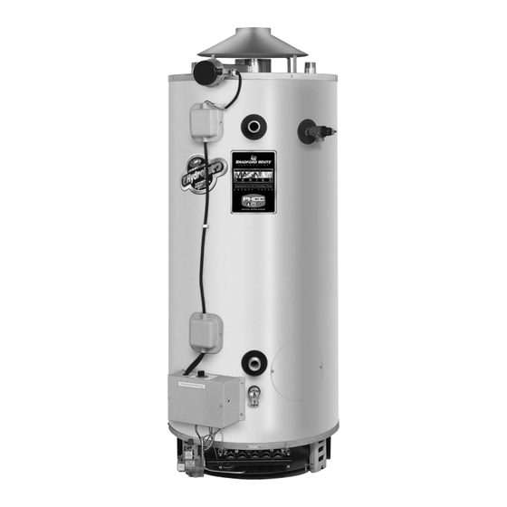
COMMERCIAL 24 VOLT FLUE DAMPER
SERIES WATER HEATER
Manual 47324A
Gas Water Heaters
SERVICE
MANUAL
and Instructions for Service
Troubleshooting Guide
(To be performed ONLY by
qualified service providers)
Models Covered
by This Manual:
For The Bradford White
"D" Series Models:
D38T155
D75T(125,160,300)
D65T(370,399)
D80T(180,199,250)
D80T(425,505)
D100T(199,250)
D80L(399,450,505)
D100L(199,250,270,300)
D100S(199,250)
Save this manual for future reference
Advertisement
Table of Contents

Related Manuals for Bradford White D75T125


Summary of Contents for Bradford White D75T125
- Page 1 SERIES WATER HEATER Gas Water Heaters SERVICE MANUAL Troubleshooting Guide and Instructions for Service (To be performed ONLY by qualified service providers) Models Covered by This Manual: For The Bradford White “D” Series Models: D38T155 D75T(125,160,300) D65T(370,399) D80T(180,199,250) D80T(425,505) D100T(199,250) D80L(399,450,505) D100L(199,250,270,300)
-
Page 2: Table Of Contents
Table of Contents Page eF Service Procedure Introduction - - - Tool required for service - - - Sequence of Operation - - - Troubleshooting - - - Thermostat Circuit Testing D24-I Pilot Operation Testing D24-II Main Burner Operation testing D24-III Main Burner &... -
Page 3: Introduction
It is intended for this manual to be used by qualified service personal for the primary purpose of troubleshooting analysis and repair of the Bradford White 24 Volt Flue Damper Series Water Heater. Understanding the sequence of operation section of this manual will contribute greatly to troubleshooting this product. -
Page 4: Sequence Of Operation
Sequence of Operation Thermostat calls for heat. The relay closes on the thermostat board, sending 24 volts from the “COM” terminal of the thermostat board to the flue damper. Flue damper begins to rotate open. Once damper is full open, 24 volts is allowed to continue through damper to the “TH”... -
Page 5: Troubleshooting
TROUBLESHOOTING CAUTION Use Caution Not to Damage Connectors when making Voltage Measurements or Jumping Terminals DANGER Verify Primary and secondary voltage 120 volt exposure. Use Caution at the transformer To Avoid Personal Injury. (see photo 1) Rear terminals primary Ignition Module LED Status (120 VAC) OFF = No power to module If LED on ignition module is flashing,... -
Page 6: Thermostat Circuit Testing
SERVICE PROCEDURE D24-I Thermostat Circuit Testing CAUTION DANGER Be Careful When Making Voltage 120 volt exposure. To avoid personal injury, Measurements or Jumping Terminals use caution while performing this procedure. Not to Damage or Deform Connectors or Connector Pins. This procedure assumes the flue damper is in working order. Be sure damper opens under its own power when the thermostat circuit is by-passed. - Page 7 SERVICE PROCEDURE D24-I Thermostat Circuit Testing Thermister Resistance Testing Upper Thermister: 1. Determine resistance value of upper thermister. Test across Upper thermister location grey wires. (see photo 9). (applicable models) 2. Draw quart of water off T&P valve. Using a thermometer, determine water temperature.
-
Page 8: Pilot Operation Testing
SERVICE PROCEDURE D24-II Pilot Operation Testing CAUTION DANGER Be Careful When Making Voltage 120 volt exposure. To avoid personal injury, Measurements or Jumping Terminals use caution while performing this procedure. Not to Damage or Deform Connectors or Connector Pins. Condition: Pilot will not light, Ignition module LED is “ON”... - Page 9 SERVICE PROCEDURE D24-II Pilot Operation Testing CAUTION DANGER Be Careful When Making Voltage 120 volt exposure. To avoid personal injury, Measurements or Jumping Terminals use caution while performing this procedure. Not to Damage or Deform Connectors or Connector Pins. Condition: Pilot lights, no flame signal.
-
Page 10: Main Burner Operation Testing
SERVICE PROCEDURE D24-III Main Burner Operation Testing CAUTION DANGER Be Careful When Making Voltage 120 volt exposure. To avoid personal injury, Measurements or Jumping Terminals use caution while performing this procedure. Not to Damage or Deform Connectors or Connector Pins. Condition: Main burner will not light, Ignition module LED is “ON”... - Page 11 SERVICE PROCEDURE D24-III Main Burner Operation Testing CAUTION DANGER Be Careful When Making Voltage 120 volt exposure. To avoid personal injury, Measurements or Jumping Terminals use caution while performing this procedure. Not to Damage or Deform Connectors or Connector Pins. Condition: Main burner short cycle Check gas (line) pressure to the...
-
Page 12: Main Burner & Pilot Removal & Inspection
SERVICE PROCEDURE D24-IV Main Burner & Pilot Removal and Inspection WARNING Heater components may be HOT when performing the following steps in this procedure. Take necessary precaution to prevent personal injury. Gas Valve Wire Leads Main Burner Removal Burner Rack Gas Valve Mounting Control Knob... - Page 13 SERVICE PROCEDURE D24-IV Main Burner & Pilot Removal and Inspection Pilot Shield Pilot Burner Removal Step 1. With burner rack removed from heater, disconnect pilot tube connection from gas valve Step 2. Remove the two pilot burner mounting screws securing the pilot and pilot shield in place. Step 3.
-
Page 14: Flue Baffle Removal, Inspection
SERVICE PROCEDURE D24-V Flue Baffle Removal, Inspection WARNING Heater components may be HOT when performing the following steps in this procedure. Take necessary precaution to prevent personal injury. Step 1. Disconnect (unplug) water heater from electrical supply. Step 2. Disconnect venting from draft diverter and remove draft diverter from top of water heater. Step 3. -
Page 15: Anode Removal & Inspection
SERVICE PROCEDURE D24-VI Anode Removal and Inspection WARNING Heater components may be HOT when performing the following steps in this procedure. Take necessary precaution to prevent personal injury. Step 1. Disconnect (unplug) water heater from electrical supply. Step 2. Turn “OFF” water supply to water heater. Step 3. -
Page 16: Generic Parts List
Generic Parts List 1. Draft Diverter w/Leg Kit. 11. Flue Core. 21. Brass Drain Valve. 2. Draft Diverter. 12. 1" x ¾" Reducer Bushing. 22. Cold Water Inlet Nipple (side). 3. Draft Diverter Leg. 13. Nipple T&P Valve. 23. Gas Valve Harness. 4. - Page 17 Generic Parts List 1A. Draft Panel. 11A. Pilot Mounting Screw. 21A. 1" Close Nipple Black. 2A. Burner Rack. 12A. Burner Tube Support. 22A. Pilot Regulator. 3A. Burner Tube. 13A. Manifold Bracket. 23A. Pilot Solenoid. 4A. Gas Valve. 14A. C-Cane Manifold. 24A.
- Page 18 Generic Parts List 1C. Temperature Control Knob. 9C. Power Cord train Relief Bushing. 2C. Potentiometer Gasket. 10C. Power Cord. 3C. Potentiometer (Temperature Control). 11C. Pilot wire Strain Relief Bushing. 4C. 7/8" Snap Bushing. 12C. 7/8" Snap Bushing. 5C. Temperature Scale Plate. 13C.
-
Page 19: Glossary Of Terms
Glossary of Terms Alternating Current BTU/H British Thermal Units Carbon Monoxide Carbon Dioxide Direct Current Energy Cut Off Ground fault interrupt Gallons per Minute Hertz Light Emitting Diode Oxides of Nitrogen National Pipe Thread Pounds per Square Inch Volt Amps Volts Alternating Current W.C. - Page 20 Email parts@bradfordwhite.com techserv@bradfordwhite.com www.bradfordwhite.com...