Table of Contents
Advertisement
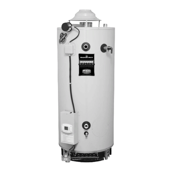
COMMERCIAL 24 VOLT FLUE DAMPER
SERIES WATER HEATER WITH HONEYWELL
INTEGRATED CONTROL SYSTEM
Manual 47985A REV 08/18
Gas Water Heaters
SERVICE
MANUAL
and Instructions for Service
Troubleshooting Guide
(To be performed ONLY by
qualified service providers)
Models Covered
by This Manual:
For The Bradford White
"D" Series Models:
D38T155
D75T(125,160,300)
D65T(370,399)
D80T(180,199,250)
D80T(425,505)
D100T(199,250)
D80L(399,450,505)
D100L(199,250,270,300)
D100S(199,250)
Save this manual for future reference
Advertisement
Table of Contents

Related Manuals for Bradford White D Series


Summary of Contents for Bradford White D Series
- Page 1 INTEGRATED CONTROL SYSTEM Gas Water Heaters SERVICE MANUAL Troubleshooting Guide and Instructions for Service (To be performed ONLY by qualified service providers) Models Covered by This Manual: For The Bradford White “D” Series Models: D38T155 D75T(125,160,300) D65T(370,399) D80T(180,199,250) D80T(425,505) D100T(199,250) D80L(399,450,505) D100L(199,250,270,300)
-
Page 2: Table Of Contents
Table of Contents Page Service Procedure Introduction - - - Tools Required for Service - - - Sequence of Operation - - - Troubleshooting - - - Thermostat Circuit Testing D24-I Pilot Operation Testing D24-II Main Burner Operation Testing D24-III Main Burner &... - Page 3 FEATURES OF HONEYWELL INTEGRATED CONTROLS SYSTEM Attractive digital water heater display on control panel for setting and displaying the temperature setpoint. Pressing temperature up and down buttons changes the temperature setpoint. Temperature format may be displayed in degrees F or degrees C.
-
Page 4: Introduction
It is intended for this manual to be used by qualified service personnel for the primary purpose of troubleshooting analysis and repair of the Bradford White 24 Volt Flue Damper Series Water Heater. Understanding the sequence of operation section of this manual will contribute greatly to troubleshooting this product. - Page 5 Specifications Power Supply Dedicated 120 VAC, 60 Hz., 15 A Current Draw Less than 5 Amps. Gas Supply Connection 1" NPT connection to gas valve for 370,000 Btu/hr. and over for natural gas, ¾" NPT for rest. Schedule 40 black iron pipe recommended. Approved Gas Type Natural or Propane.
-
Page 6: Sequence Of Operation
Sequence of Operation Thermostat calls for heat. The control board sends 24 volts from damper terminal #2 on the control plug to the flue damper. Flue damper begins to rotate open. Once the flue damper is fully open, the damper end switch closes and 24 volts is allowed to continue through damper to damper pin terminal #5. -
Page 7: Troubleshooting
Troubleshooting CAUTION Use Caution Not to Damage Connectors when making Voltage Measurements or Jumping Terminals Water Heater Fault: Water heater does not operate Display Error Code: Water heater display does not operate - blank display Check main power supply to water heater - fuse, circuit breaker, plug receptacle, line cord or wiring to water heater. - Page 8 Troubleshooting CAUTION Use Caution Not to Damage Connectors when making Voltage Measurements or Jumping Terminals From previous page Error code #55 on display. Remove damper from heater and Does damper blade move to the full Does water heater begin to jump black &...
- Page 9 Troubleshooting Using Control Display for Servicing the Water Heater ACCESSING SERVICE MODE ON THE WATER HEATER DISPLAY (FOR SERVICE PERSONNEL ONLY) The display has a “service mode” for changing the maximum setpoint and accessing information in aiding servicing of the water heater.
- Page 10 Troubleshooting 1. Max Setpoint (Display/Change) Max Setpoint value in Water Heater Display °F Setpoint idle Status Operational SELECT 2a. Water Temperature Average (Displays average if there are two sensors - sensor temperature displayed if single sensor is used). Water Temp °F idle Status...
- Page 11 Troubleshooting Flame Current of Pilot Flame Sensor (Displays only in the Heating Cycle) Heating Flame Current Operational Status SELECT 4. Setpoint (Display/Change) setpoint °F idle Operational Status SELECT °F/°C (Display/Change) setpoint °F °F/C° idle Operational Status SELECT Differential (Display only - shows the differential of the thermostat) °F Differential idle...
- Page 12 Troubleshooting 7. Software Version (Display only) Soft idle Status Operational SELECT 8. Error Code History (Displays if there are present error codes or up to 10 previous error codes). Water Heater Display will show a “--“ if there are no error codes. WARNING Setting the water temperature to the maximum set point can...
- Page 13 Troubleshooting Step 2: Press “Set” button to enter setting mode. “Max Setpoint” will flash to indicate setting mode. °F Setpoint idle Status Operational SELECT Step 3: Press the “UP” or “DOWN” buttons to change the maximum setpoint value. This will limit the maximum setpoint the user can select.
- Page 14 Troubleshooting Step 5: 30 Seconds after the last button press, the Water Heater Display will go back to “User Mode”. It will read “Max Setpoint” without showing a temperature value if the temperature setpoint is at the maximum setting. The Water Heater Display can be set back to the “User Mode”...
- Page 15 Troubleshooting Step 3: For water heaters using two temperature sensors, pressing the “Select” button again displays the Lower Sensor temperature reading. “Lower Sensor” will be displayed in the lower left side of the status window of the water heater display. °F idle Operational...
- Page 16 Troubleshooting Step 2: Press the “Set” button to enter the setting mode. “Setpoint” will flash in the water heater display. setpoint °F idle Status Operational SELECT Step 3: To raise the temperature setpoint, press the “Temperature Up” button until the desired temperature is shown on the water heater display.
- Page 17 Troubleshooting Step 5: When the desired setpoint is reached on the water heater display, press the “Set” button to confirm the new setpoint. “Setpoint” stops flashing in the water heater display. setpoint °F idle Status Operational SELECT To Display and Change Temperature Format (°F/°C): To Change Temperature Format in Display from °F to °C or °C to °F: Step 1: While in “Service Mode”, press “Select”...
- Page 18 Troubleshooting Step 3a: Press “Temperature Up” button to change temperature format to °C °C °F/C° idle Operational Status SELECT Step 3b: Press “Temperature Down” button to change temperature format to °F °F °F/C° idle Operational Status SELECT Step 4: Press “Set” button to confirm °F or °C format. °F/°C will stop flashing °F °F °F/C°...
- Page 19 Troubleshooting Step 5: Pressing “Select” button will return display to setpoint in format selected (°F or °C) immediately °F idle Operational Status Lower Sensor SELECT Error Codes and Error History Display: If there is an operating problem with the water heater, an error code number will appear on the water heater display with “Service Needed”...
- Page 20 Troubleshooting To view previous error codes: Step 1: In “Service Mode press the “Select” button until the next display after the “Software Version”. If there are no current error codes, the display will show -- . °F idle Operational Status SELECT Step 2: Press the “Temperature Down”...
- Page 21 Troubleshooting Step 4: Press the “Temperature Down” button to change to the previous code index, code #9. idle Operational Status SELECT Step 5: Press the “Select” button for code index #9 to view if there are any code numbers. idle Operational Status SELECT...
- Page 22 Troubleshooting ERROR CODE DEFINITIONS If the water heater has an operating problem, there will be a number in the water heater display with “Service Needed” shown below the error code number. Note the error code and the definition in the chart below.
- Page 23 WARNING The following procedure is for service and installation personnel only. Resetting lockout conditions without correcting the malfunction can result in a hazardous condition. If an error code is displayed (except for #4, low flame sense current), the water heater will be in a “lockout condition” with the water heater display showing the error code number and “Service Needed”...
-
Page 24: Thermostat Circuit Testing
SERVICE PROCEDURE D24-I Thermostat Circuit Testing CAUTION DANGER Be Careful When Making Voltage 120 volt exposure. To avoid personal injury, Measurements or Jumping Terminals use caution while performing this procedure. Not to Damage or Deform Connectors or Connector Pins. This procedure assumes the flue damper is in working order. Be sure damper opens under its own power when the thermostat circuit is by-passed. - Page 25 SERVICE PROCEDURE D24-I Thermostat Circuit Testing WARNING! Do not operate water heater without verifying that the overheating condition has been corrected. Condition: Water Heater Not Operating Display shows error code “65” High Water Temperature (over 200 deg. F) Continued Once cause of overheating condition has been diagnosed and corrected, the control may be reset Reconnect and switch on power to the water heater.
- Page 26 SERVICE PROCEDURE D24-I Conditions: Upper or Lower Sensor Reading Thermostat Circuit Testing Faulty, High Water Temperature, or suspect thermostat is not accurate. Sensor Resistance Testing Upper Sensor 1. Determine resistance value of upper sensor. Test across grey wires. Upper thermister location (applicable models) 2.
-
Page 27: Pilot Operation Testing
SERVICE PROCEDURE D24-II Pilot Operation Testing CAUTION DANGER Be Careful When Making Voltage 120 volt exposure. To avoid personal injury, Measurements or Jumping Terminals use caution while performing this procedure. Not to Damage or Deform Connectors or Connector Pins. Condition: Pilot will not light or stay lit, Error codes 62, or 63 shown on Water Check across “MV/PV”... - Page 28 SERVICE PROCEDURE D24-II Pilot Inspection Condition: Error code 57: Flame Rod Shorted to Ground Disconnect power. Shut off gas Check to see if pilot shield is touching supply to water heater. Slide out pilot flame sensor or flame sensor Check pilot flame sense wire for burner assembly (see section on touching pilot hood.
- Page 29 SERVICE PROCEDURE D24-II Pilot Operation Testing CAUTION DANGER Be Careful When Making Voltage 120 volt exposure. To avoid personal injury, Measurements or Jumping Terminals use caution while performing this procedure. Not to Damage or Deform Connectors or Connector Pins. Condition: Pilot lights, no or low flame signal.
-
Page 30: Main Burner Operation Testing
SERVICE PROCEDURE D24-III Main Burner Operation Testing CAUTION DANGER Be Careful When Making Voltage 120 volt exposure. To avoid personal injury, Measurements or Jumping Terminals use caution while performing this procedure. Not to Damage or Deform Connectors or Connector Pins. Checking MV &... - Page 31 SERVICE PROCEDURE D24-III Main Burner Operation Testing CAUTION DANGER Be Careful When Making Voltage 120 volt exposure. To avoid personal injury, Measurements or Jumping Terminals use caution while performing this procedure. Not to Damage or Deform Connectors or Connector Pins. Condition: Main burner short cycles.
-
Page 32: Main Burner & Pilot Removal & Inspection
SERVICE PROCEDURE D24-IV Main Burner & Pilot Removal and Inspection WARNING Heater components may be HOT when performing the following steps in this procedure. Take necessary precaution to prevent personal injury. Gas Valve Wire Leads Main Burner Removal Burner Rack Gas Valve Mounting Control Knob... - Page 33 SERVICE PROCEDURE D24-IV Main Burner & Pilot Removal and Inspection Pilot Shield Pilot Burner Removal Step 1. With burner rack removed from heater, disconnect pilot tube connection from gas valve Step 2. Remove the two pilot burner mounting screws securing the pilot and pilot shield in place. Step 3.
- Page 34 SERVICE PROCEDURE D24-IV Control Board Replacement DANGER 120 volt exposure. To avoid personal injury, unplug while performing this procedure. Control board replacement Step 2: Unplug wire connections from board. Step 1: Disconnect Power Depress Wire connections plastic tabs Step 3: To remove board, tilt control panel to the right and slide control hook tabs from slots in control panel.
-
Page 35: Flue Baffle Removal, Inspection
SERVICE PROCEDURE D24-V Flue Baffle Removal, Inspection WARNING Heater components may be HOT when performing the following steps in this procedure. Take necessary precaution to prevent personal injury. Step 1. Disconnect (unplug) water heater from electrical supply. Step 2. Disconnect venting from draft diverter and remove draft diverter from top of water heater. -
Page 36: Anode Removal & Inspection
SERVICE PROCEDURE D24-VI Anode Removal and Inspection WARNING Heater components may be HOT when performing the following steps in this procedure. Take necessary precaution to prevent personal injury. Step 1. Disconnect (unplug) water heater from electrical supply. Step 2. Turn “OFF” water supply to water heater. Step 3. - Page 37 SERVICE PROCEDURE D24-VI Anode Removal and Inspection Approximate Anode Rod Locations Page 37...
-
Page 38: Generic Parts List
Generic Parts List 16/16A 17/17A 1. Draft Diverter w/Leg Kit 11. Flue Core 20. Burner Assembly Complete 2. Draft Diverter 12. 1" x ¾" Reducer Bushing 21. Brass Drain Valve 3. Draft Diverter Leg 13. Nipple T&P Valve 22. Cold Water Inlet Nipple (side) 4. - Page 39 Generic Parts List 1A. Draft Panel 11A. Pilot Mounting Screw 2A. Burner Rack 12A. Burner Tube Support 3A. Burner Tube 13A. Manifold Bracket 4A. Gas Valve 14A. C-Cane Manifold 5A. Burner Manifold 15A. Manifold Straight 6A. Main Burner Orifice 16A. Manifold Bracket 7A.
- Page 40 Generic Parts List 1B. Temperature Display 11B. Power Cord Strain Relief 2B. Control Box Cover 12B. Pilot Wire Strain Relief 3B. Integrated Control Board 13B. Secondary Transformer Wiring Harness 4B. Screw 8-16 X ½ PHCR 14B. Primary Transformer Wiring Harness 5B.
-
Page 41: Glossary Of Terms
Glossary of Terms Alternating Current BTU/H British Thermal Units per Hour Carbon Monoxide Carbon Dioxide Direct Current Energy Cut Off Ground fault interrupt Gallons per Minute Hertz Light Emitting Diode Oxides of Nitrogen National Pipe Thread Pounds per Square Inch Volt Amps Volts Alternating Current W.C. - Page 42 NOTES Page 34...
- Page 43 NOTES Page 34...
- Page 44 Email parts@bradfordwhite.com techserv@bradfordwhite.com www.bradfordwhite.com...