
Related Manuals for Garmin GMC 7 Series


Summary of Contents for Garmin GMC 7 Series
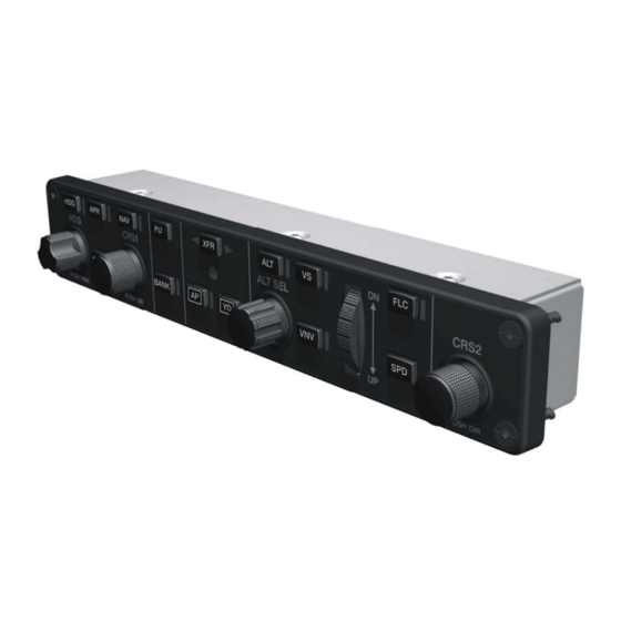
- Page 1 GMC 7XX Installation Manual (GMC 710 Shown) 190-00303-70 September, 2008 Revision F...
- Page 2 Garmin. Garmin hereby grants permission to download a single copy of this manual and of any revision to this manual onto a hard drive or other electronic storage medium to be viewed and...
- Page 3 CURRENT REVISION DESCRIPTION Page Section Revision Description of Change Number(s) Number 1.5.2.2 Changed DO-160E to DO-160D Removed reference to G1000 Line Maintenance and Configuration Manual Updated GMC 710 Outline Drawing DOCUMENT PAGINATION Section Page Range Table of Contents i – vi Section 1 1-1 –...
- Page 4 NOTE Throughout this document references made to the GMC 7XX shall equally apply to the GMC 705, GMC 710, and GMC 715 except where specifically noted. Page ii GMC 7XX Installation Manual Revision F...
-
Page 5: Table Of Contents
TABLE OF CONTENTS PARAGRAPH PAGE GENERAL DESCRIPTION......................1-1 1.1 Introduction............................1-1 1.2 Equipment Description ........................1-1 1.3 Interface Summary..........................1-1 1.4 Technical Specifications ........................1-2 1.5 Certification ............................1-3 1.6 Reference Documents ........................1-7 1.7 Limited Warranty..........................1-8 INSTALLATION OVERVIEW ......................2-1 2.1 Introduction............................2-1 2.2 Installation Materials .........................2-1 2.3 Installation Considerations ........................2-1 2.4 Cabling &... - Page 6 LIST OF FIGURES FIGURE PAGE 2-1 GMC 7XX Locking Socket .......................2-2 3-1 GMC 7XX ¼ Turn Fastener ......................3-2 A-1 GMC 705 Cutout Drawing (Not To Scale)..................A-1 A-2 GMC 710 Cutout Drawing (Not To Scale)..................A-3 A-3 GMC 715 Cutout Drawing (Not To Scale)..................A-5 A-4 GMC 705 Outline Drawing ......................
- Page 7 The table is current at the time of publication of this manual (see date on front cover) and is subject to change without notice. Authorized Garmin Sales and Service Centers are encouraged to access the most up-to-date bulletin and advisory information on the Garmin Dealer Resource web site at www.garmin.com using their Garmin-provided user name and password.
- Page 8 This page intentionally left blank Page vi GMC 7XX Installation Manual Revision F 190-00303-70...
-
Page 9: General Description
This manual presents mechanical and electrical installation requirements for installing the GMC 7XX as part of a Garmin Integrated Flight Deck. The GMC 7XX can be integrated into a variety of airframes under an appropriate TC or STC. Each airframe installation may vary. Use only approved (type or supplemental type) data for specific installation instructions in a particular aircraft. -
Page 10: Technical Specifications
GMC 705 Environmental Qualification Form, Garmin part number 005-00466-03 GMC 710 Environmental Qualification Form, Garmin part number 005-00213-01 GMC 715 Environmental Qualification Form, Garmin part number 005-00384-10 To obtain a copy of this form, see the dealer/OEM portion of the Garmin web site (www.garmin.com). 1.4.2 Physical Characteristics... -
Page 11: Certification
The article may be installed only if performed under 14 CFR part 43 or the applicable airworthiness requirements. At the time of publication, installations of this TSO approved article are only approved when installed in an aircraft as part of a Garmin Integrated Flight Deck. - Page 12 1.5.1 TSO/ETSO Compliance 1.5.1.1 GMC 705 GMC 705 GMC 705 TSO/ETSO/ (011-01737-00) (011-01737-20) Function Applicable LRU Applicable LRU SAE/ RTCA/ EUROCAE SW Part SW Part Numbers Numbers 006-D1125-0(_) 006-D1125-0(_) TSO-C9c 006-B0742-0(_) 006-B0742-0(_) Automatic Pilots ETSO-C9c except except SAE AS402B 006-B0742-00 006-B0742-00 through through...
- Page 13 1.5.1.2 GMC 710 GMC 710 GMC 710 TSO/ETSO/ (011-01020-00) (011-01020-10) Function SAE/ RTCA/ Applicable LRU Applicable LRU EUROCAE SW Part SW Part Numbers Numbers 006-B0387-(__) except 006-B0387-00 006-B0387-(__) TSO-C9c through except Automatic Pilots ETSO-C9c 006-B0387-02 006-B0387-00 SAE AS402B through 006-B0387-07 006-B0387-19 through 006-B0387-19...
- Page 14 3. Garmin was granted a deviation from TSO-C9c subpart A (c), which requires marking the weight of the unit on the unit. Garmin will provide this information in the installation manual in lieu of marking on the serial tag.
-
Page 15: Reference Documents
3. Garmin was granted a deviation from TSO-C9c subpart A (c), which requires marking the weight of the unit on the unit. Garmin will provide this information in the installation manual in lieu of marking on the serial tag. -
Page 16: Limited Warranty
Garmin retains the exclusive right to repair or replace the unit or software or offer a full refund of the purchase price at its sole discretion. SUCH REMEDY SHALL BE YOUR SOLE AND EXCLUSIVE REMEDY FOR ANY BREACH OF WARRANTY. -
Page 17: Installation Overview
GMC 715 Unit Only, (011-01430-00) 010-00554-00 * Garmin recommends this GMC 710 for new TC/STC approvals. Garmin does not recommend the use of 011-01020-00 for new TC/STC approvals. Unit maintains the same form, fit, and function as the original GMC 710. -
Page 18: Cabling & Wiring
Use AWG #24 or larger wire for all connections unless otherwise specified by the aircraft manufacturer or Garmin. The standard pin contacts supplied in the connector kit are compatible with up to AWG #22 wire. In cases where some installations have more than one unit sharing a common circuit breaker, sizing and wire gauge is based on aircraft circuit breaker layout, length of wiring, current draw of units, and internal unit protection characteristics. -
Page 19: Installation Procedure
If the unit is damaged, notify the carrier and file a claim. To justify a claim, save the original shipping container and all packing materials. Do not return the unit to Garmin until the carrier has authorized the claim. -
Page 20: Backshell Assembly
The GMC 7XX does not provide valid outputs until the aircraft post installation configuration procedures are completed. The GMC 7XX must be installed with a Garmin Integrated Flight Deck and have FAA approved configuration data. The GMC 7XX serves as the user interface for the installer configuring the GFC 700 AFCS. -
Page 21: Continued Airworthiness
3.6 Continued Airworthiness Maintenance of the GMC 7XX is “on condition” only. For regulatory periodic functional checks, refer to approved aircraft maintenance manuals or manual supplements for actual aircraft maintenance requirements. GMC 7XX Installation Manual Page 3-3 190-00303-70 Revision F... - Page 22 This page intentionally left blank Page 3-4 GMC 7XX Installation Manual Revision F 190-00303-70...
-
Page 23: System Interconnects
SYSTEM INTERCONNECTS Pin Function List 4.1.1 P7101 View of J7101 connector from back of unit Pin Name RS-232 OUT 1 RS-232 IN 1 RS-232 OUT 2 RS-232 IN 2 POWER GROUND SIGNAL GROUND AIRCRAFT POWER 1 SIGNAL GROUND AIRCRAFT POWER 2 CONTROL UNIT REMOTE POWER OFF LIGHTING BUS HI LIGHTING BUS LO... -
Page 24: Serial Data
Serial Data 4.3.1 Serial Data Electrical Connections 4.3.1.1 RS-232 Pin Name Connector RS-232 OUT 1 P7101 RS-232 IN 1 P7101 RS-232 OUT 2 P7101 RS-232 IN 2 P7101 SIGNAL GROUND P7101 SIGNAL GROUND P7101 The RS-232 outputs conform to EIA Standard RS-232C with an output voltage swing of at least ±5V when driving a standard RS-232 load. -
Page 25: Appendix A Outline & Installation Drawings
APPENDIX A OUTLINE & INSTALLATION DRAWINGS ° 0 ± ± ± ± Figure A-1. GMC 705 Cutout Drawing (Not To Scale) GMC 7XX Installation Manual Page A-1 (Page A-2 blank) 190-00303-70 Revision F... - Page 26 APPENDIX A OUTLINE & INSTALLATION DRAWINGS ° Figure A-2. GMC 710 Cutout Drawing (Not To Scale) GMC 7XX Installation Manual Page A-3 (Page A-4 blank) 190-00303-70 Revision F...
- Page 27 APPENDIX A OUTLINE & INSTALLATION DRAWINGS PANEL CUTOUT 12X R.065 1.65 8.310 211.07 .094 2.39 8.160 207.26 4X .170 4.32 1.150 29.21 1.090 27.69 2X .885 22.48 2X .595 15.11 .230 5.84 2X .577 14.65 2X .448 11.38 2.180 55.37 0 0.0 2X .448 11.38 BEZEL OUTLINE...
- Page 28 APPENDIX A OUTLINE & INSTALLATION DRAWINGS Figure A-4. GMC 705 Outline Drawing GMC 7XX Installation Manual Page A-7 (Page A-8 blank) 190-00303-70 Revision F...
- Page 29 APPENDIX A OUTLINE & INSTALLATION DRAWINGS 8.61 218.7 .45 11.3 3.20 81.3 NOTES: DIMENSIONS: INCHES[mm] DIMENSIONS ARE SHOWN FOR REFERENCE ONLY. 1.27 32.1 .4 10 FRONT SURFACE OF PANEL 7.92 201.2 9.50 241.3 4.9 126 .05 1.1 1.54 39.1 1.65 41.9 1.13 28.7 .92 23.4 Figure A-5.
- Page 30 APPENDIX A OUTLINE & INSTALLATION DRAWINGS 8.12 206.2 .46 11.6 3.20 81.4 1.27 32.2 .6 15 7.69 195.2 9.03 229.4 5.2 132 1.3 32 .08 2.0 2.14 54.4 2.30 58.4 .34 8.6 1.47 37.2 .91 23.0 NOTES: UNLESS OTHERWISE SPECIFIED DIMENSIONS: INCHES[mm] DIMENSIONS ARE SHOWN FOR REFERENCE ONLY.
- Page 31 APPENDIX A OUTLINE & INSTALLATION DRAWINGS Figure A-7. GMC 705 Installation Drawing GMC 7XX Installation Manual Page A-13 (Page A-14 blank) 190-00303-70 Revision F...
- Page 32 APPENDIX A OUTLINE & INSTALLATION DRAWINGS Figure A-8. GMC 710 Installation Drawing GMC 7XX Installation Manual Page A-15 (Page A-16 blank) 190-00303-70 Revision F...
- Page 33 APPENDIX A OUTLINE & INSTALLATION DRAWINGS GMC 715 UNIT CONNECTOR KIT 011-01430-( ) 011-01040-01 MOUNTING HW KIT 011-00821-( ) Figure A-9. GMC 715 Installation Drawing GMC 7XX Installation Manual Page A-17 (Page A-18 blank) 190-00303-70 Revision F...
-
Page 34: Appendix B Interconnect Example
APPENDIX B INTERCONNECT EXAMPLE Figure B-1. GMC 7XX Example Interconnect GMC 7XX Installation Manual Page B-1 (Page B-2 blank) 190-00303-70 Revision F...