Table of Contents
Advertisement
Quick Links
Advertisement
Table of Contents

Related Manuals for Guardian 55 ES


Summary of Contents for Guardian 55 ES
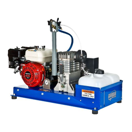
- Page 1 MODEL 55 ES ©2008 GUARDIAN ULV EQUIPMENT PRODUCT OF ADAPCO, INC., SANFORD, FL...
- Page 2 Hazard control and accident prevention are dependent upon the awareness, concern, prudence, and proper training of the personnel involved in the operation, transport, maintenance, and storage of the equipment. This manual covers the operating instructions, illustrations, and parts lists for: Guardian 55 ES...
-
Page 3: Table Of Contents
TABLE OF CONTENTS MODEL 55 ES Contents SPECIFICATIONS ............................5 INTRODUCTION ............................7 SERVICING THE ENGINE ..........................7 DIRECTION REFERENCE ..........................8 SAFETY INFORMATION ..........................9 SIGNAL WORDS ............................9 BEFORE OPERATION CONSIDERATIONS ....................10 OPERATION CONSIDERATIONS ....................... 12 MAINTENANCE AND STORAGE ........................13 FAMILIARIZATION ............................ - Page 4 FLOW CALIBRATION PROCEDURES ......................25 FLOW DIAGRAM ............................27 TROUBLESHOOTING ............................ 28 ILLUSTRATED PARTS BREAKDOWN ......................29 GUARDIAN 55 ES ............................. 29 GUARDIAN 55 ES PARTS LIST ........................30 GUARDIAN 55 ES PARTS LIST ........................31 GUARDIAN ULV LIMITED WARRANTY ......................33...
-
Page 5: Specifications
SPECIFICATIONS Guardian 55 ES Engine Make: Honda Model GX160 Horse Power: Engine type: Air cooled, 4-stroke, OHV, Single cylinder Bore & Stroke: 68 x 45 mm (2.7 x 1.8 in.) Displacement: 163 cm (9.9 cu. In) Ignition system: Transistorized magneto... - Page 6 Capacity Fuel: 0.95 U.S. gallons (3.6 liter) Formulation: 2.5 Gallon (9.46 liter) Natural/opaque Flow Control No pump Siphon Orifice disk Orifice sizes .020ø through .061ø (9 sizes) Formulation filter: Inline Gauges Pressure: 0-150 PSI Throttle & Choke Control Throttle: manual Choke: manual Finish:...
-
Page 7: Introduction
MANUFACTURER’S AUTHORIZED REPLACEMENT PART MAY ADVERSELY AFFECT THE PERFORMANCE, DURABILITY OR SAFETY OF THIS PRODUCT. USE OF OTHER THAN ADAPCO/GUARDIAN ULV REPLACEMENT PARTS WILL VOID THE WARRANTY. For some pictoral clarity, some illustrations and figures in this manual may show guards, or shrouds removed. -
Page 8: Direction Reference
DIRECTION REFERENCE The “Right” and “Left”, “Front” and “Rear” of the machine are refereced from the operator’s right and left when standing behind the vehicle and facing in the normal forward direction of the vehicle. Additionally, the ULV sprayer is designed to be placed in the back of a vehicle with the engine and compressor facing the rear. -
Page 9: Safety Information
SAFETY INFORMATION GENERAL SAFETY INFORMATION Your ULV sprayer is only as safe as the operator. Carelessness or operator error may result in serious bodily injury or death. Hazard control and accident prevention are dependent upon the awareness, concern, prudence, and proper training of the personnel involved in the operation, transport, maintenance, and storage of the equipment. -
Page 10: Before Operation Considerations
The message that follows the symbol contains important information about safety. To avoid injury and possible death, carefully read the message! Be sure to understand the causes of possible injury or death. Signal Word: The Signal word is a distinctive word found on the safety decals on the machine and throughout this manual that alerts the viewer to the existence and relative degree of the hazard. - Page 11 shoes is advisable and may be required by some local ordinances or insurance regulations. 4. Always wear hearing protection. Operating this machine for prolonged periods of time without hearing protection can cause permanent loss of hearing. 5. Keep the Spray machine and attachments in good operating condition. Keep all guards, or shrouds in place.
-
Page 12: Operation Considerations
h. If fuel is spilled on clothing, change clothing immediately. i. Replace gas cap and tighten securely. 7. Fill chemical tank to the indicated full level not to exceed 2.5 U.S. gallons (9.46 liters). a. Keep fill nozzle or funnel securely in the opening at all time while chemical is being transferred. -
Page 13: Maintenance And Storage
6. NEVER walk directly into the air/chemical blast from the nozzle when insecticide or any other formulation is being atomized. 7. DO NOT direct the air/chemical discharge toward bystanders or allow anyone near the machine while in operation. 8. DO NOT run the engine inside a building or a confined area without proper ventilation. -
Page 14: Familiarization
FAMILIARIZATION OPERATOR CONTROLS The standard configuration of the Guardian 55 ES incorporates manual controls of the engine and the spray on/off. Optional electrical remote spray on/off is available by using a 12-volt electric solenoid valve in place of the manual spray ball valve to control the flow of chemical to the nozzle. This remote control device plugs into a “cigarette”... -
Page 15: Spray Valve (Ball Valve)
A remote spray on/off option is available for the Guardian 55 ES in the form of a 12-volt electric solenoid valve which is installed in place of the manual valve. -
Page 16: Atomization Nozzle
2.5 gallon jugs. This cap is fitted with a draw tube and compression style coupling and vent. Simply replace the existing cap of your “RTU” jug with the new Guardian cap and place the jug in the same location as standard tank and strap securely in place. -
Page 17: Installation
INSTALLATION COLD FOG GENERATOR (ULV SPRAYER) CONTENTS FACTORY FLUID LEVELS When you receive your Guardian ULV sprayer, the fluid levels will be as follows: Engine oil full Compressor full Fuel tank empty Formulation tank empty Each machine is fully tested functionally and appropriate fluid levels are services beforehand. -
Page 18: Engine Starting & Stopping
2/3 full in the sight gauge on the side of the compressor. ENGINE STARTING & STOPPING The Guardian 55ES has either a 4 hp Kawasaki or 4 hp Honda engine that has an on/off ignition switch connected electrically to the engine. When the engine is cold, the manual choke will be... -
Page 19: Engine Symbols
required to start the engine. After the engine is warm, the choke should not be required in most cases. Refer to the engine symbols below for definitions Engine Symbols Fuel On Fuel Off Choke off Choke On Fuel selected Fuel valve to In this position, To aid in cold Run fast mode... -
Page 20: Maintenance
MAINTENANCE CHECKING ENGINE CRANKCASE OIL LEVEL 1. The engine oil level should be checked after every 8 hours of operation or daily as instructed in the Engine Operator’s Manual furnished with this machine. 2. Level the machine and engine to ensure accurate inspection and to prevent overfilling 3. -
Page 21: Compressor Lubrication
COMPRESSOR LUBRICATION A clear sight gauge or window is located on the air compressor indicating lubrication oil level. Ensure the oil level is maintained to 2/3 full as visible on the sight gage. Use 30 weight, non-detergent oil for temperatures above 56°F, or 20 weight non-detergent oil for temperatures from 32-55°F. - Page 22 In the final analysis, the correct belt tension is just enough tension to keep the belt from slipping under normal load conditions.
-
Page 23: Lubrication And Maintenance
LUBRICATION AND MAINTENANCE BREAK-IN ( AFTER FIRST 8 HOURS) 8 HOURS (DAILY) EVERY 25 HOURS EVERY 50 HOURS EVERY 100 HOURS EVERY 200 HOURS Every 300 HOURS OR ANNUALLY EVERY PROCEDURE COMMENTS Check all hardware for tightness Check drive belt for proper alignment Change engine oil (break-in) See Engine Owner's Manual Check engine oil level... -
Page 24: Calibration
Perform these calibrations in the order outlined in this manual. FLOW CALIBRATION DESCRIPTION Flow to the atomization nozzle is controlled on the Guardian 55 ES by 2 variables, pressure and orifice size. Generally speaking, the maximum pressure potential of this unit under normal operating conditions is approximately 80 psi which produces the greatest vacuum or siphoning. -
Page 25: Flow Calibration Procedures
FLOW CALIBRATION PROCEDURES 1. Disconnect hose on upper side of orifice disk fitting with gloved hands. Pull back on the black collar and pull the tubing straight out until disconnected. 2. Loosen the black orifice fitting to reveal both a filter screen and orifice disk. Place the desired disk chosen from the proceeding table into the fitting and retighten. - Page 26 3. With hose still attached to the formulation tank, unscrew the hose and draw tube assembly from the formulation tank and place into a graduated cylinder. Reconnect the tube from the nozzle to the top of the orifice fitting. 4. Add chemical to the graduated cylinder until well above the bottom of draw tube and note volume in the cylinder.
-
Page 27: Flow Diagram
FLOW DIAGRAM BALL VALVE ATOMIZATION NOZZLE COMPRESSED ORIFICE & FILTER ASSEMBLY ORIFICE IN-LINE FILTER FORMULATION TANK... -
Page 28: Troubleshooting
TROUBLESHOOTING Troubleshooting guidelines are outlined for both the engine and air compressor in the corresponding owner’s manuals of each. For problem identification, refer to these manuals for further guidance. For all other troubleshooting symptoms, refer to the table below. If the troubleshooting symptom you are experiencing is not listed in the below table or in either of the engine or air compressor troubleshooting sections, contact the manufacturer for service and support. -
Page 29: Illustrated Parts Breakdown
ILLUSTRATED PARTS BREAKDOWN GUARDIAN 55ES USING 2.5 GAL RTU JUG OPTION 14 15 33 14 50 49... -
Page 30: Guardian 55 Es Parts List
GUARDIAN 55 ES PARTS LIST Ref. Ref. Part No. Description Part No. Description 1865-601 K12 Air Compressor 1865-627 Orifice assembly 1/4"FPT x 1/4" barb 1865-622 GX200K1(Honda) Recoil start engine. 1865-629-X Orifice disk, X = size (see orifice chart) 1865-103 Air Compressor Aluminum Flywheel... -
Page 31: Guardian 55 Es Parts List
GUARDIAN 55 ES PARTS LIST Ref. Part No. Description 1865-629-020 Orifice disk, .020" diameter -025 Orifice disk, .025" diameter -030 Orifice disk, .030" diameter -035 Orifice disk, .035" diameter -040 Orifice disk, .040" diameter -045 Orifice disk, .045" diameter -051 Orifice disk, .051"... - Page 32 NOTES:...
-
Page 33: Guardian Ulv Limited Warranty
ADAPCO, Inc. and found in the reasonable judgment of ADAPCO, to be defective in materials or workmanship, will be repaired or replaced by ADAPCO or an Authorized Guardian ULV Service Dealer without charge for parts and labor during the periods specified below. - Page 34 NALED as the active ingredient. This Guardian ULV machine will not be warranted for any period if the active ingredient NALED is used for any purpose. Guardian Model: 55 ES_________ Serial Number: _________________________Record the serial number of your machine here...