
Related Manuals for Life Fitness Elevation and Platinum Club Series


Summary of Contents for Life Fitness Elevation and Platinum Club Series
- Page 1 Elevation and Platinum Club Series Treadmill (95T / PCST with Discover SE3HD / ST Consoles) Assembly Instructions M051-00K92-0000 REV GB...
- Page 3 Latin America and Caribbean* Spain Hong Kong Life Fitness, LLC Life Fitness IBERIA Life Fitness Asia Pacific LTD 10601 W Belmont Ave C/Frederic Mompou 5,1º1ª 26/F, Global Trade Square Franklin Park, IL 60131 U.S.A. 08960 Sant Just Desvern Barcelona...
- Page 4 User and Service Documents Link https://lifefitness9512.zendesk.com/hc/en-us https://www.lftechsupport.com/web/document-library/documents Additional information is available online using the links above. أ علاه إل ر إبط باستخدإم إ لإ ن تر نت على إضافية معلومات تتوفر 点击上面的链接可在线获取更多信息。 Flere oplysninger er tilgængelige online gennem linket ovenfor. Bijkomende informatie is online beschikbaar via bovenstaande link.
-
Page 5: Table Of Contents
Copyright 2022, Life Fitness, LLC. All Rights Reserved. Life Fitness, Hammer Strength, Cybex, ICG and SCIFIT are registered trademarks of Life Fitness, LLC and its affiliated companies and subsidiaries. Disclaimer: Images and specifications are current as of the date of publication and are subject to change. -
Page 6: Getting Started
• Life Fitness Family of Brands does not warrant nor guarantee that component parts used in the manufacture of products offered under the Life Fitness Family of Brands are latex-free. Users of these products must take all necessary precautions to prevent accidental contact that could lead to an adverse latex reaction. - Page 7 • Allow LCD consoles to “normalize” with respect to temperature for one hour before plugging the unit in and using. • When the product is not in use, Life Fitness recommends unplugging the product. Disconnect from the electrical outlet when not in use, and before putting on or taking off parts. To disconnect, turn power OFF at the ON/OFF switch, then remove plug from electrical outlet.
-
Page 8: Consignes De
Consignes de Sécurité Veuillez lire toutes les instructions avant usage. AVERTISSEMENT : Une utilisation incorrecte ou excessive de l'appareil peut entraîner des blessures. Life Fitness Family of Brands Recommande VIVEMENT aux utilisateurs de passer un examen médical complet avant d'entamer un programme d'entraînement, et tout particulièrement dans les cas suivants : antécédents familiaux d'hypertension (pression sanguine trop élevée) ou de pathologies cardiaques, utilisateurs de 45 ans ou plus, tabagisme, hypercholestérolémie (taux de cholestérol sanguin trop élevé), obésité, absence d'exercice physique depuis un an ou plus. - Page 9 à la clientèle. Nous vous en fournirons de nouvelles. Les étiquettes d’avertissement sont expédiées avec les appareils et doivent être installées avant utilisation de ces derniers. Life Fitness Family of Brands n’est pas responsable des étiquettes manquantes ou endommagées.
-
Page 10: Set-Up
Set-Up Read the entire manual before setting up the treadmill. Place the treadmill where it will be used before beginning the setup procedure. Electrical Power Requirements The treadmill requires a dedicated* line with isolated neutral according to the electrical configurations listed in the chart below. -
Page 11: How To Position And Stabilize The Safety Clearances
How to Position and Stabilize the Treadmill Follow all safety instructions. Move the treadmill to the location in which it will be used. NOTE: See How to Adjust and Tension the Striding Belt to center the striding belt. Safety Clearances The following information is supplied as regional reference data regarding safety clearances around the exterior of the treadmill. -
Page 12: Turning The Unit On
Cable TV Hook-Up The console can receive both analog and digital signals. Life Fitness is not responsible for the installation of CATV service or components required for the delivery of CATV service. An external TV signal input via a 75-ohm coaxial cable must be present before TV setup can occur. -
Page 13: Immobilization Method - Discover
Immobilization Method - Discover Console The purpose of immobilizing the treadmill is to prevent unauthorized use. The system causes immobilization of the treadmill when activated. 1. Tap the LANGUAGE icon to access the SELECT LANGUAGE screen. 2. Tap the lower part of the screen in the following sequence: Lower-Left, Lower-Right, Lower-Left, and Lower-Right. 3. -
Page 14: Product Overview
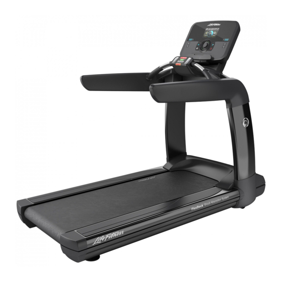
2. Product Overview Product Features Item Description Qty. Console Contact Heart Rate Sensors Transport Wheels Walking Belt Leg Leveler Emergency Stop Lanyard Emergency Stop Magnet Cup Holder Activity Zone Page 12 of 35... -
Page 15: Mounting And Dismounting The User Position
Mounting and Dismounting the Treadmill Use the handrails to enhance stability when mounting or dismounting a treadmill. Never mount or dismount the treadmill while the running belt is moving. Use the STOP button on the console to end a workout and stop the running belt. -
Page 16: Service And Technical Data
3. Service and Technical Data Preventive Maintenance Tips NOTE: Safety of the equipment can be maintained only if the equipment is examined regularly for damage or wear. Keep the equipment out of use until defective parts are repaired or replaced. Pay special attention to parts that are subject to wear, as outlined below. -
Page 17: Troubleshooting The Polar
Using a voltmeter, verify power at outlet. If no power exists, reset circuit breaker at panel. Line cord is damaged. Replace line cord. Contact Life Fitness Customer Support. Line cord is improperly seated in socket. Inspect power connections at wall outlet and at machine for proper contact. -
Page 18: Treadmill
• Incorrect console or power supply. • Line cord at treadmill • Power switch • All console connections • All lower electronics connections Contact Life Fitness Customer Support. Unit resets randomly or pauses. Probable Cause Corrective Action Power source is insufficient. -
Page 19: Strap
Troubleshooting the Polar ® Heart Rate Chest Strap Heart rate reading is erratic or absent entirely Probable Cause Corrective Action Belt transmitter electrodes are not wet enough to pick up Wet the belt transmitter electrodes. accurate heart rate readings. Belt transmitter electrodes are not laying flat against the Ensure the belt transmitter electrodes are laying flat skin. - Page 20 NOTE: Do not exceed one full turn of the adjusting screws in either direction. If after one full turn the belt does not track properly, contact Life Fitness Customer Support. Do not overtighten the tensioning bolts while making belt adjustments. Overtightening of bolts may over stretch and damage the striding belt or roller.
- Page 21 Tensioning an Existing Striding Belt 1. Press GO and operate the treadmill for five minutes at 5.0 MPH (8.0 KPH). NOTE: Do not run or walk on belt! 2. Reduce the speed to 2.0 MPH (3.2 KPH). Walk on the treadmill. Tightly grip the handrails and apply force with feet on the striding belt near the motor cover against the moving belt direction.
-
Page 22: Assembly
4. Assembly Hardware and Required Tools Item Description M6 X 14 BUTTON HEAD SCREW M6 X 20 SOCKET HEAD SCREW M5 X 14 PHILLIPS PAN HEAD SCREW M6 X 35 BUTTON HEAD SCREW M12 X 30 HEX BUTTON HEAD SCREW M12.5 WASHER M6.5 WASHER #10-16 X 8 PHILLIPS PAN HEAD SCREW... -
Page 23: Attach Line Cord To
Attach Line Cord to Base 1. Turn treadmill base on its side. 2. Loosen the screw located nearest the edge of the line cord bracket. Remove the other screw on the line cord bracket and retain hardware. Item Description Qty. Line Cord Bracket M4 X 10 Screw 1.69 Nm (1.25 ft. -
Page 24: Remove Motor
4. Fully tighten the screw previously loosened on the line cord bracket. Secure the line bracket with the previously removed screw. Remove Motor Cover Remove motor cover and hardware. Retain all parts. Item Description Qty. Motor Cover Screw: 10-16 X 8, PHL, PAN, ST, ZB Page 22 of 35... -
Page 25: Attach Uprights
Attach Uprights 1. Run cables up through the left upright. 2. Attach left upright to upright support. 3. Run cables up through the right upright. 4. Attach right upright to upright support. 5. Tighten all hardware 50%. Item Description Qty. Left Upright M12 X 30 Hex Button Head Screw M12.5 Washer... -
Page 26: Secure Bridge Assembly To
Secure Console Mounting Bracket to Bridge Assembly Item Description Qty. Console Mounting Bracket M6 X 85 Screw M6.5 Washer M6 Lock Nut 10.84 Nm (8 ft. lbs.) Secure Hardware into Ergo Bar Assembly Item Description Qty. Ergo Bar Assembly M6 X 20 Socket Head Screw M6.5 Washer 6 Nm ( 53.1 in. -
Page 27: Attach Bridge Top
Attach Bridge Top Cover 1. Run cables through opening of bridge top cover. 2. Attach bridge top cover to bridge assembly. Item Description Qty. Top Cover M6 X 14 Button Head Screw 2.8-3.9 Nm ( 25-35 in. lbs.) Page 25 of 35... -
Page 28: Covers
Attach Outer Handrail Covers Item Description Qty. Outer Handrail Cover, Right Outer Handrail Cover, Left M6 X 14 Button Head Screw 2.0 Nm (17.5 in. lbs.) Attach Inner Handrail Covers Item Description Qty. Inner Handrail Cover, Right Inner Handrail Cover, Left M6 X 14 Button Head Screw 2.0 Nm (17.5 in. -
Page 29: Attach Console Neck
Attach Console Neck Spacer Item Description Qty. Console Neck Spacer M6 X 14 Button Head Screw 2.8-3.9 Nm ( 25-35 in. lbs.) Attach Activity Zone 1. Remove access door. 2. Connect Emergency Stop cables. 3. Secure activity zone assembly to ergo bar assembly. 4. -
Page 30: Assembly
Attach Console and Console Rear Shroud Assembly Item Description Qty. Console M5 X 14 Phillips Pan Head Screw 1.9 Nm (1.4 ft. lbs.) Item Description Qty. Rear Console Shroud Assembly M6 X 14 Button Head Screw 2.8 - 3.9 Nm (25 - 25 in. lbs.) Page 28 of 35... -
Page 31: Attach Lower Frame Extrusion Assemblies
Attach Lower Frame Extrusion Assemblies Two options for assembling the lower frame extrusions to the upper extrusions are shown. • Attach top of the lower frame extrusion assembly first. • Attach bottom of the lower frame extrusion assembly first. NOTE: Left frame extrusion shown in all images. Remove and discard liners on foam pad spacers on both the left and right lower frame extrusion assemblies. -
Page 32: Attach Lower Extrusion Spacer
Attach bottom of the lower frame extrusion assembly first. 1. Snap bottom of lower frame extension into place. 2. Swing up the lower frame extrusion and slide the top of the lower frame extrusion into the corresponding slot on the upper extrusion assembly. Attach Lower Extrusion Spacer Attach rubber spacers on the left and right sides of the treadmill. -
Page 33: Uprights
Secure Upright Covers to Uprights Item Description Qty. Upright Cover, Right Upright Cover, Left #10-16 X 8 Phillips Pan Head Screw 3.38 Nm (2.5 ft. lbs.) #8-8 X 12 Phillips Pan Head Screw 1.1 Nm (10 in. lbs.) Attach Rear End Caps Item Description Qty. -
Page 34: Grommets
Insert Cup Holders and Handrail Grommets Item Description Qty. Cup Holders Rubber Grommets Install Coaxial and Ethernet Cables Item Description Qty. Coaxial Cable External Ethernet Cable Page 32 of 35... - Page 35 5. Specifications Heavy / Commercial (95T) EN ISO 20957 Class S Designed Use Home (PCST) EN ISO 20957 Class H Maximum User Weight 400 lbs. / 181 kg 0.5 - 14.0 MPH (0.8 - 23 KPH) in 0.1 increments (95T) Speed Range 0.5 - 12.0 MPH (0.8 - 19 KPH) in 0.1 increments (PCST) Elevation Range...
-
Page 36: What Is Covered
Who Pays Transportation and Insurance For Service If the Product or any covered part must be returned to a service facility for repairs, We, Life Fitness Family of Brands, will pay all transportation and insurance charges for the first year. You are responsible for transportation and insurance charge after the first year. -
Page 37: Changes In Warranty Not Effects Of State Laws
Changes in Warranty Not Authorized No one is authorized to change, modify or extend the terms of this limited warranty. Effects of State Laws This warranty gives you specific legal rights, and you may have other rights which vary from state to state and country by country.