Table of Contents
Advertisement
Quick Links
Advertisement
Table of Contents

Related Manuals for AGFA Drystar 4500 Plug & Play


Summary of Contents for AGFA Drystar 4500 Plug & Play
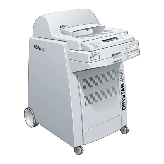
- Page 1 AGFA Drystar 4500 Plug & Play Installation manual English Edition...
- Page 2 Agfa-Gevaert N.V. Agfa-Gevaert N.V. makes no warranties or representation, expressed or implied, with respect to the accuracy, completeness or usefulness of the information contained in this document and specifically disclaims warranties of suitability for any particular purpose. Agfa-Gevaert N.V. shall under no circumstances be liable for any damage arising from the use or inability to use any information, apparatus, method or process disclosed in this document.
-
Page 3: Contents Of The Packages
Contents of the packages Contents of the packages. Set of cables Two film packs Phillips screwdriver Drystar 4500 Set of documents Set of manuals Required tools. Included Not included Wire cutter 6 mm Allen key 7 mm hex key Philips screwdriver Standard screwdriver 3/18 2805F EN 20050128... -
Page 4: Remove The Packing Materials
Remove the packing materials Remove the cardboard box. Remove the foam blocks. A c c e s s o F R O N r i e s T S I D E Remove the plastic bag. Remove the front panel protection. Create a descending slope. - Page 5 Unscrew the fixations Remove eight screws and two fixation Take 6 mm Allen key. bars. MOBILE / SEISMIC INSTALLATION ONLY: reuse the fixation bars and screws to secure the printer at its final location. MOBILE INSTALLATION If the printer is to be installed on a van, continue unpacking as described and refer to the illustration when securing the printer to the van floor.
- Page 6 Unpack the accessories Check all accessories. Refer to the Packing slip for a complete list of accessories. Check all documents. Refer to the Packing slip for a complete list of documents. Return the packing materials. ,720 DALL 4,438 PAT. 9497 U.S.
-
Page 7: Environment Specifications
Environment specifications Environment requirements. Power requirements. ◆ ◆ Ventilated room, The AC outlet must have either of following specifications: ◆ away from direct sunlight, ◆ 100-120 V, 60 Hz, 16/15 A, ◆ away from sources of dust, humidity, heat and cold, ◆... - Page 8 Remove the transport protection blocks Open the upper input tray Remove the protection foam. and the top cover. Close the upper tray and the top cover. Open the lower input tray. Remove the protection foam. Close the lower input tray. 8/18 2805F EN 20050128...
- Page 9 Remove the protection straps Open both input trays and the top cover. Take wire cutter. Cut the two upper red straps. Cut the two lower red straps. Cut the red strap, and close the input Open the film input assembly. trays and the top cover.
- Page 10 Remove the side covers Remove the two adhesive straps and Open the front cover. close the front cover. Take standard screwdriver. Unlock the quarter turn fastener. Push two pins upwards and remove the Remove the left side cover. right side cover. 10/18 2805F EN 20050128...
- Page 11 Install blocking plate and belt On the right, loosen and refasten the Take 7 mm hex key. red blocking plate. On the left, pull the belt [1] over the pulley [2]. Turn the pulley only slowly to assist the mounting of the belt. Slowly turn the pulley by hand to assist the belt.
- Page 12 Reinstall the side covers Install the Phillips screwdriver for future use. When reinstalling the side covers, take into account the positioning pins at the bottom and the top. Reinstall the right side cover on the Lift the top pins into their positioning bottom positioning pins.
-
Page 13: Connect The Cables
Connect the cables Select the power cable. Locate the mains connector. Connect the power cable. Mount the strain relief. Locate the network connector and Move the printer to its final destination connect the network cable. and lock the wheel. 13/18 2805F EN 20050128 2805F EN 20050128... - Page 14 Load film in the upper input tray Open the upper input tray. The films delivered with the printer are intended for test purposes only. Load 8x10” test films in the upper tray and 10x12” test films in the lower tray. Place the film pack in the tray.
- Page 15 Load film in the lower input tray Open the tray and push the partition Open the film pack. clips down (for film size 10x12”). Check the icons on the film bag before loading films. Place the film pack in the tray (with Close the lower input tray (verify that perforated protective sheet down).
- Page 16 Startup Drystar 4500 Wait until the READY status is Press the POWER button. displayed. POWER POWER STOP STOP OWER Press the lower left corner to open the keypad cover. 16/18 2805F EN 20050128...
-
Page 17: Configure Network Settings
Configure network settings Ask your network manager The printer is configured with the the following information: following APIPA addresses: Printer IP address: Printer IP address: 169.254.10.10 Netmask: Subnet mask: 255.255.0.0 Router IP address: Called AE_Title: Select and initiate the printer Select and initiate printer calibration. - Page 18 18/18 2805F EN 20050128...