
Related Manuals for JVC VN-C215VP4U


Summary of Contents for JVC VN-C215VP4U
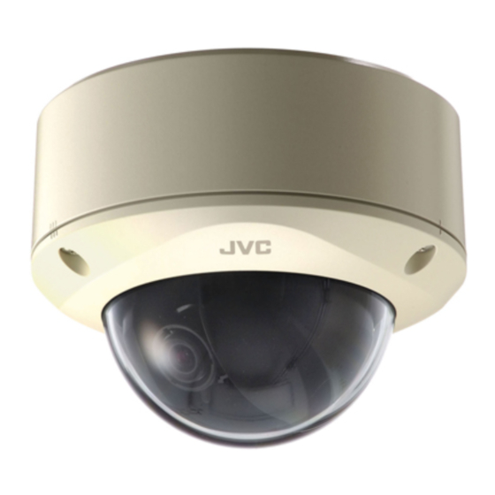
- Page 1 FIXED IP DOME CAMERA VN-C215VP4U For Customer Use: Enter below the Serial No. which is located on the body. Retain this information for future reference. VN-C215VP4U Model No. Serial No. INSTRUCTIONS LST0529-001A...
-
Page 2: Introduction
Introduction Safety Precautions FOR USA These are general IMPORTANT SAFEGUARDS and certain items may not apply to all appliances. 1. Read all of these instructions. 2. Save these instructions for later use. 3. All warnings on the product and in the operating instructions should be adhered to. 4. - Page 3 Information for USA This device complies with part 15 of the FCC Rules. Changes or modifications not approved by JVC could void the user's authority to operate the equipment. This equipment has been tested and found to comply with the limits for a Class A digital device, pursuant to Part 15 of the FCC Rules.
- Page 4 If you wish to dispose of this product, please visit our web page Union. www.jvc-europe.com to obtain information about the take-back of the product. [Other Countries outside the European Union] If you wish to dispose of this product, please do so in accordance with applicable national legislation or other rules in your country for the treatment of old electrical and electronic equipment.
- Page 5 Please refer to your dealer for installation. Rating label is pasted at the bottom of the camera. JVC is not liable for any compensation if you drop the camera due to insecure mounting by not following the installation description. Pay careful attention during installation.
-
Page 6: Main Features
: Indicates the reference page numbers and reference items. About the contents of this manual ● All rights reserved by JVC. Unauthorized duplication or reprinting of this manual, in whole or in part, is strictly prohibited. ● Windows is a registered trademark of Microsoft Corporation in the U.S. -
Page 7: Table Of Contents
Contents Introduction Safety Precautions ... 2 Main Features ... 6 Contents ... 7 Operating Environment ... 8 Cautionary Notes ... 8 Name and Function of Parts ... 10 Features ... 14 Setup Procedures ... 16 Removing the dome cover ... 17 Mounting the base ... -
Page 8: Operating Environment
Introduction Operating Environment PC Specification Requirements : Windows XP (Professional or Home Edition) (SP2) : Pentium4 1.5 GHz (or higher) Memory : 1 GB and above Hard disk space : Free space of 20 MB and above Video Card : 1024 768 pixels or higher, True Color (24 or 32 bits) Web browser : Internet Explorer Version 6.0... - Page 9 Others This product has a built-in AGC circuit. When AGC is On , the product sensitivity increases automatically at dark places and the image on the screen may appear grainy. This is not a malfunction. When White Balance is set to Auto , the principle of automatic tracking white balance circuit may cause the color of the image to be different from the actual color of the object,...
-
Page 10: Name And Function Of Parts
(A Pg. 17)(A Pg. 21) Note : ● To mount the camera using an electrical box, please check with your dealer or nearest JVC servicing center. Holes for connection cable and piping This hole is for pulling out the connection cable. - Page 11 ● The AC 24 V power supply should conform to the following : Class 2 only (Fou USA), Isolated power supply only (For Europe). ● Please consult your nearest JVC dealer regarding heaters. Base GND cable (Purple) (A Pg. 25) Power supply/Alarm signal cable (A Pg.
- Page 12 Introduction Name and Function of Parts (continued) Inside the camera [10BASE-T/100BASE-TX(PoE)] 10BASE-T/100BASE-TX terminal This is a 10BASE-T/100BASE-TX terminal. It connects to the network via LAN cable. (A Pg. 26) Rotation Knob This knob rotates the lens section and adjusts the tilting of the image. (A Pg. 28) Rotation center mark (A Pg.
- Page 13 [MONITOR] Monitor terminal (RCA pin) (A Pg. 28) Heater power connector This power connector is used when the camera is installed with a heater (sold separately: KA- ZH215). Heater space Memo : ● When mounting the heater (sold separately :KA-ZH215), read the instruction manual of the heater carefully before mounting.
-
Page 14: Features
Introduction Features Monitoring Via Built-in Viewer VN-C215VP4U comes with a built-in ActiveX viewer. Monitoring of VN-C215VP4U images using the computer is possible by installing this built-in viewer on the computer. Images that are currently displayed may also be captured in the computer’s hard disk. - Page 15 Restrictions on Clients It is possible for VN-C215VP4U to permit or deny image acquisition of designated IP addresses. (A Pg. 60) Control via customized application software The following uses are also possible by developing a customized application software that supports the API of VN-C215VP4U.
-
Page 16: Setup Procedures
Setup Procedures The connection and setup procedures are described as below. Make sure you touch the metal surface of the [MONITOR] terminal to release the static electricity from your body. Static electricity may cause the camera to malfunction. Make sure that various parts of the camera do not drop on the floor when mounting the base to the ceiling or connecting the cable of the camera unit. -
Page 17: Removing The Dome Cover
Removing the dome cover Remove the dome cover Loosen the dome cover fastening screws (x3) with the wrench (supplied) and remove the dome cover. Memo : ● The dome cover is connected to the base via a fall-prevention wire. Fall-prevention wire Remove the inner dome The inner dome is secured by 3 claws. -
Page 18: Cable Connection
Setup Mounting the base (continued) Mount the fall-prevention wire to the base (The fall-prevention wire is not attached) Remove the fall-prevention wire mounting screw of the base and mount the fall-prevention wire. Note : ● Also pay careful attention to the length, strength, wiring and material (insulation quality) of the fall-prevention wire to be used. -
Page 19: Mounting The Camera
Mounting the camera Fill up the piping hole and mounting hole with sealant, mount the camera to the base and insert silica gel. Fill up the holes with sealant Use sealant to fill up the mounting holes (x2) to which the piping hole and screws are mounted. Memo :... - Page 20 ● Be sure to replace the silica gel when you reconnect or reinstall the camera during repair or maintenance. ● For replacement, please consult your nearby JVC’s dealer. Use silica gel of service parts number LW40500-001A for the parts to be replaced. Note :...
-
Page 21: Mounting The Camera Via Electrical Box
Mounting the camera via electrical box Mount the base to an electrical box. Remove the camera unit from the base (A Pg. 17) Mount the base to the electrical box Use two mounting holes and two M4 screws to mount the base to the electrical box. Memo :... -
Page 22: Mounting The Camera Via Piping
Setup Mounting the camera via piping Use a piping hole to mount the camera. Use the piping hole at the bottom of the base to mount the camera Remove the camera unit from the base (A Pg. 17) Mount the fall-prevention wire to the base (A Pg. - Page 23 Using the piping hole at the side of the base to mount the camera When the camera is not directly mounted on a ceiling, use the piping hole at the side of the base to mount the camera to the piping. Remove the camera unit from the base and mount the fall-prevention wire (A Pg.
-
Page 24: Power Connection
Setup Power Connection Electricity can be supplied to this product either by using the PoE or connecting to the DC 12 V power supply. When electricity is supplied to the camera, the status indicator blinks, and turns off when startup is complete. Note :... -
Page 25: Base Gnd Cable Connection
VN- C215VP4U under the same LAN environment and wait for at least 10 minutes. Access to VN-C215VP4U may be denied unless you restore the power supply of all network devices under the same LAN environment. -
Page 26: Heater Cable Connection
● The AC 24 V power supply should conform to the following : Class 2 only (Fou USA), Isolated power supply only (For Europe). ● Please consult your nearest JVC dealer regarding heaters. About heater cables Maximum... -
Page 27: Alarm Input/Output Cable Connection
Alarm Input/Output Cable Connection Connect the alarm input/output cables with external devices such as a sensor, buzzer, etc. Signal name Alarm input 1 Alarm input 2 Alarm output 1 Alarm output 2 Cable to use ● Length of 50 m or shorter ●... -
Page 28: Adjusting Images
Setup Adjusting Images When the camera is mounted, adjust the image settings while looking at the actual image. Mounting the test monitor Connect the [MONITOR] terminal of the camera to the test monitor to adjust the camera shooting direction, field angle and focus. T When configuring, turn on the power of the camera. - Page 29 Adjusting field angle, focus and brightness Once you have decided the shooting direction, you can adjust the field angle, focus and brightness. Note : ● Be sure to hold the dome cover over the lens when adjusting the focus. The dome cover is made thicker for performance purposes.
-
Page 30: Mounting The Inner Dome
Setup Mounting the inner dome After all settings are complete, mount the inner dome to the camera. Mount the inner dome Mount the inner dome to the claws (x3). Inner dome Note : ● Mount the inner dome without covering the lens. - Page 31 Note : ● Secure the dome cover tightly. Insecure mounting may increase humidity, fog up the camera or the cover may drop. ● When the cover is removed again after mounting the dome cover, adjust the field angle. ● Make sure that the fall-prevention wire of the dome cover is not caught between the dome cover and the base.
-
Page 32: Setting
● Ensure that there is sufficient network bandwidth for the data volume to be sent out by VN-C215VP4U. ● Data volume to be sent by VN-C215VP4U varies with the settings and number of distributions. ● The maximum bit rate from VN-C215VP4U is about 9 Mbps. -
Page 33: Ip Address Settings
: 255.255.255.0 Default gateway : None Memo : ● To set a static IP address for VN-C215VP4U, connect VN-C215VP4U, switching hub and computer for setting using a straight LAN cable of Category 5 and above. Set up the computer for setting the IP address. - Page 34 Setting IP Address Settings (continued) IP Address setting at the computer Set the computer to an IP address that enables communication with VN-C215VP4U. Click [Start] ● Select in the order of [Control Panel]-[Network Connection]-[Local Area]. The computer with which Internet Explorer is launched automatically selects the connected network ●...
- Page 35 Changing the IP address using the Internet Explorer Launch the Internet Explorer on the computer When proxy setting is enabled in the Internet Explorer, follow the steps below to disable the proxy of the Internet Explorer ● Select in the order of [Tools]-[Internet Options...]-[Connections]-[LAN Setting], followed by deselecting the check for [Use a proxy server for your LAN] in [Proxy Server] of the [Local Area Network(LAN)Settings] window.
- Page 36 Setting IP Address Settings (continued) Changing the IP address using the Internet Explorer (continued) Launch the Internet Explorer Enter the following IP address in the address field. http://192.168.0.2 Memo : ● If the proxy server setting in Internet Explorer is enabled, you may not be able to specify the IP address directly.
- Page 37 It takes about 1 minute for the camera to reboot. Memo : ● Access from this computer may fail when the IP address of VN-C215VP4U is changed. To enable access to VN-C215VP4U from the same computer, alter the IP address at the computer accordingly.
- Page 38 Setting IP Address Settings (continued) When the IP address of VN-C215VP4U is known When the IP address of VN-C215VP4U is known, it can be changed by using Internet Explorer on the computer to access the built-in web page of VN-C215VP4U.
-
Page 39: Setting Using Internet Explorer
● Click [Trusted sites] under [Tools]-[Internet Options...]-[Security]. Click on the [Sites...] button directly below, followed by deselecting the check for [Require server verification(https:) for all sites in this zone] in the displayed window. Lastly, add VN-C215VP4U web site to the zone. Example: http://192.168.0.2 ●... -
Page 40: Enter User Name And Password
Blocker]-[Pop-up Blocker Settings], and open the [Pop-up Blocker Settings] window. In the opened window, add the address of VN-C215VP4U as an allowed web site address. When plug-in tools such as the Yahoo or Google toolbar are included in the Internet... - Page 41 ● operator Image JPEG View Camera Encoding External Alarm Alarm Environment Motion Detection Utility Miscellaneous Status Operation Settings ● user Image JPEG View Utility Miscellaneous Memo : ● The Security Alarm screen appears before the top page is displayed. Press the [Yes] button to proceed.
-
Page 42: Jpeg View Page
Setting Setting Using Internet Explorer (continued) JPEG View Page This top page is displayed upon access using any of the user name admin , operator or user . The current image is displayed as a still image. Links to each page are found at the left end. The links displayed vary according to the user name. For example, in the case of admin or operator , 3 links, namely [JPEG View], [Camera] and [Encoding] will be displayed upon clicking [Image]. - Page 43 [Temporary Internet Files], and select Every visit to the page . Note : ● When a firewall is installed between VN-C215VP4U and the computer, JPEG images may not be displayed on the JPEG View page of the web browser. For such systems, check the JPEG images using the built-in viewer.
-
Page 44: Camera Page
Setting Setting Using Internet Explorer (continued) Camera Page This page is for setting the camera’s parameters. This page can be used during access using admin or operator . ● Press the [OK] button to enable the new settings upon changing. ●... - Page 45 Camera ID Character strings entered here will be written to the JPEG comment segment (item name: camera). Refer to the [API Guide] on the file formats of JPEG. For setting AGC (Auto Gain Control). Setting to On enables automatic increase in sensitivity even when brightness of the object is insufficient.
-
Page 46: Encoding Page
Setting Setting Using Internet Explorer (continued) Encoding Page This page is for setting JPEG encoding parameters. This page can be used during access using admin or operator . ● Press the [OK] button to enable the new settings upon changing. ●... - Page 47 Frame Rate For specifying the number of frames to encode per second. VN-C215VP4U is limited in its processing capacity and the specified frame rate may not be realized depending on the settings of A[Frame Size] and B[Quality/Size]. In particular, when the specified target file size is large, the upper limit of the frame rate drops.
-
Page 48: Alarm Page
Setting Setting Using Internet Explorer (continued) Alarm Page This page is for setting actions when there is an alarm. Up to 5 actions (No. 01 to No. 05) can be set. This page can be used during access using admin or operator . ●... - Page 49 Action For specifying the type of action. Disable Mail TCP/UDP Data : Input of up to 127 alphanumeric characters. Output1 Make : Change Alarm Output 1 to Make. Output2 Make : Change Alarm Output 2 to Make. Output1 Break : Change Alarm Output 1 to Break. Output2 Break : Change Alarm Output 2 to Break.
-
Page 50: Alarm Environment Page
Setting Setting Using Internet Explorer (continued) Alarm Environment Page This page is for setting alarm-related environments. This page can be used during access using admin or operator . ● Press the [OK] button to enable the new settings upon changing. ●... - Page 51 Mail For setting the mail environment when [Mail] is specified as an action of the Alarm page. [SMTP] and [POP] can be used. Configure only the [SMTP] settings in usual circumstances. Configure the [POP] settings as well if [POP before SMTP] is enabled. In addition, if FQDN is set for [SMTP Server], etc., configure also the DNS server settings on the Basic page.
- Page 52 Setting Setting Using Internet Explorer (continued) Alarm Environment Page (continued) BFTP (continued) [Pre Post Recording Frame Rate] is constrained by the frame rate as set on the Encoding page. (A Pg. 46) The actual frame rate used for transmission will be the frame rate on the Encoding page when a value that is larger than the frame rate in the Encoding page is specified.
-
Page 53: Motion Detection Page
Motion Detection Page Page for setting motion detection. ● The area valid for motion detection is displayed in blue. ● The area where motion is detected is displayed in red. - Page 54 ● The motion detection feature is not intended to prevent theft or fire. This feature may not function properly depending on the conditions of the object and settings. JVC shall not be liable for any accident or damage that occurs.
-
Page 55: Basic Page
Basic Page This page is for performing basic setting related to the network. This page can be used during access using admin . ● Press the [OK] button to enable the new settings upon changing. ● If the [OK] button is pressed upon entering an invalid value, a warning message will appear and the entry will be denied. - Page 56 IP Setting For setting the DHCP client function. Ensure to connect VN-C215VP4U to a network environment with a DHCP server when enabling the DHCP settings. If the DHCP server does not exist when DHCP is set to Enable , VN- C215VP4U will start running with the 192.168.0.2 IP address and...
-
Page 57: Details Page
Details Page This page is for performing detailed network setting. This page can be used during access using admin . ● Press the [OK] button to enable the new settings upon changing. ● If the [OK] button is pressed upon entering an invalid value, a warning message will appear and the entry will be denied. -
Page 58: Streaming Page
Setting Setting Using Internet Explorer (continued) Streaming Page This page is for setting manual multicast transmission. This page can be used during access using admin . ● Press the [OK] button to enable the new settings upon changing. ● If the [OK] button is pressed upon entering an invalid value, a warning message will appear and the entry will be denied. - Page 59 Encoding page when a value that is larger than the frame rate in the Encoding page is specified. (A Pg. 46) Memo : ● When the power of VN-C215VP4U shuts down accidentally during multicast transmission, transmission will restart automatically when VN-C215VP4U is started...
-
Page 60: Access Restrictions Page
Setting Setting Using Internet Explorer (continued) Access Restrictions Page This page is for setting client restrictions. This page can be used during access using admin . ● Press the [OK] button to enable the new settings upon changing. ● If the [OK] button is pressed upon entering an invalid value, a warning message will appear and the entry will be denied. - Page 61 Destination Restrictions may be imposed on clients accessing VN-C215VP4U using the IP address. Address Access When deny is selected, acquisition of JPEG via the IP address specified Restrictions for the [IP Address] item will be denied. However, restrictions are not imposed on access to the Web Setting page.
-
Page 62: Time Page
Access Interval For setting the time interval for access to the SNTP server. Time Displays the time on the clock of VN-C215VP4U. The clock time can be changed by entering a value. (However, second value cannot be specified.) In addition, time will be recorded in the JPEG headers distributed by VN- C215VP4U. -
Page 63: Password Page
New Password Enter again to confirm the new password. Again Note : ● Be sure to handle the password carefully in case you forget it. ● In the event that you forget the password, please consult your nearest JVC dealer. -
Page 64: Maintenance Page
Update Upgrades the firmware version of VN-C215VP4U and reboots the unit. The VN-C215VP4U settings will be saved. Copy the new firmware file to the computer on which Internet Explorer is used, and specify this file using the [Browse...] button. Press the [Update] button to start upgrading the version. -
Page 65: List Of Factory Settings Of Each Page
List of Factory Settings of Each Page Camera Page Item Camera ID Easy Day and Night Shutter Speed Back Light Compensation Off White Balance Encoding Page Item Frame Size Quality/Size Fine Reverse Flag Alarm Page Item Action 1st Trigger Max.Interval 2nd Trigger Mail Address Mail Text... - Page 66 Setting Setting Using Internet Explorer (continued) List of Factory Settings of Each Page (continued) Basic Page Item IP Setting DHCP Enable IP Address 192.168.0.2 Subnet Mask 255.255.255.0 Default Gateway 192.168.0.254 Host Name Domain Name DNS Server 0.0.0.0 Details Page Item TTL Unicast TTL Multicast 1500...
-
Page 67: Miscellaneous Page
Miscellaneous Page This page is for acquiring information. This page can be used during access using admin , operator and user . Open Source Press the [Show] button to display the software information used at VN- C215VP4U. Software... -
Page 68: Operation Page
Operation Page Displays the operating status of VN-C215VP4U. This page can be used during access using admin or operator . Total Sending Displays the total TCP/UDP bit rate sent by VN-C215VP4U as well as the individual bit rates. Bitrate Destination Displays the destination that VN-C215VP4U is sending data to. -
Page 69: Settings Page
Settings Page This page displays the version information and settings of VN-C215VP4U. This page can be used during access using admin or operator . - Page 70 Setting Setting Using Internet Explorer (continued) Settings Page (continued)
- Page 71 SNTP SNTP 無効 SNTP :0.0.0.0 サーバー...
-
Page 72: Operation
Operation Operation of Built-in Viewer Using the built-in viewer enables display of a series of images, one-shot recording of images and receiving of alarm information. Setting Up the Internet Explorer (A Pg. 73) Installing the built-in viewer (A Pg. 75) Screen Configuration of Built-in Viewer (A Pg. -
Page 73: Setting Up The Internet Explorer
Setting Up the Internet Explorer Launch the Internet Explorer on the computer When proxy setting is enabled in the Internet Explorer, follow the steps below to disable the proxy of the Internet Explorer ● Select in the order of [Tools]-[Internet Options...]-[Connections]-[LAN Setting], followed by deselecting the check for Use a proxy server for your LAN in [Proxy Server] of the [Local Area Network(LAN)Settings] window. - Page 74 Click on this button and deselect the check for [Require server verification(https:) for all sites in this zone] in the displayed window. Next, add the IP address of VN-C215VP4U. If the setting is factory default, add the following web site to the zone. http://192.168.0.2 ●...
-
Page 75: Installing The Built-In Viewer
Installing the built-in viewer Enter the URL of the built-in viewer in the address field of Internet Explorer For example, if the IP address of VN-C215VP4U is 192.168.0.2, enter as follows: http://192.168.0.2/cgi-bin/c215viewing.cgi Enter the URL of the built-in viewer of this camera. -
Page 76: Screen Configuration Of Built-In Viewer
Operation Operation of Built-in Viewer (continued) Screen Configuration of Built-in Viewer ● VN-C215VP4U is set to encode at 15 fps by default. - Page 77 Display Size Pause Capture Setup Appears blinking when alarm packets are sent from VN-C215VP4U to the computer. The alarm will continue blinking until the auto clear operation of the alarm is performed. Clicking the blinking button turns the light off.
-
Page 78: Built-In Viewer Settings
Encoding settings (File Size, Frame Rate, Frame Size). (A Pg. 46) Select On to display the camera ID. The camera ID can be set on the Camera page of the VN-C215VP4U unit. (A Pg. 44) Select On to display the time. - Page 79 The frame rate set at the VN-C215VP4U unit will be the upper limit to the acquisition frame rate of the viewer. For example, when VN-C215VP4U is set to 15 fps , transmission will only be possible at 15 fps even when the client requests for 30 fps.
- Page 80 In order to use this feature, it is necessary to set the alarm action for sending the notification to VN-C215VP4U via TCP. Set the destination of the alarm action to the IP address of the computer that is used to operate the built-in viewer, and set the [TCP/UDP Port Number] item to the same number as the K[Alarm Port Number] item below.
-
Page 81: Quitting The Built-In Viewer
● To restart the built-in viewer, launch the Internet Explorer and enter the URL of the built-in viewer in the address field. For example, if the IP address of VN-C215VP4U is 192.168.0.2, enter as follows: http://192.168.0.2/cgi-bin/c215viewing.cgi ● After the Security Warning screen appears, press the [OK] button to proceed. -
Page 82: Shortcut For Built-In Viewer
Operation Operation of Built-in Viewer (continued) Shortcut for Built-in Viewer Creating a shortcut for the built-in viewer on the Desktop screen of the computer saves you the trouble of having to enter the URL in the Internet Explorer. Create the shortcut using the procedures below. Launch the Internet Explorer Right-click on Internet Explorer on the screen and select [Create Shortcut]... -
Page 83: Others
TCP images cannot be played back Causes and Countermeasures ● You can search for the VN-C215VP4U unit using the attached Search Tool . ● HCP client is set to On in the default settings. ● When the DHCP client is set to On and VN-... - Page 84 TCP/UDP Causes and Countermeasures ● Start multicast transmission manually from the Streaming page of VN-C215VP4U. ● In the case of multicast reception at the built-in viewer, check that the multicast address and port number of the built-in viewer settings coincide with those on the Streaming page of VN- C215VP4U.
-
Page 85: Specifications
Specifications Camera Unit Image pickup device : 1/4 inch Interline transfer Effective pixels : Approx. 380,000 pixels 768 494 (V) [Monitor Output] Monitor output x 1 (75 , 1 Vp-p) Horizontal resolution : 540 TV lines (typ.) Minimum object illumination Color mode : 2.5 lx (typ., 50 %, F1.3, wide-angle lens, AGC ON) - Page 86 (Supply by power feeding device that supports Power over Ethernet) AC24 VH 50 Hz/60 Hz (When using KA-ZH215) Consumption current 0.5 A (VN-C215VP4U) 18 W(KA-ZH215) Ambient -10 I to 50 I temperature (14 g to 122 g) (operation) 0 I to 40 I...
- Page 87 Dimension [Unit: mm (inch)] 121(4-3/4) 113(4-1/2) G3/4-14 UNC screw for piping (bottom surface, side surface) 160(6-1/4) T Specifications and appearance of this unit and related products are subject to change for product improvement without prior notice. (3/8)
- Page 88 LST0529-001A © 2006 Victor Company of Japan, Limited...