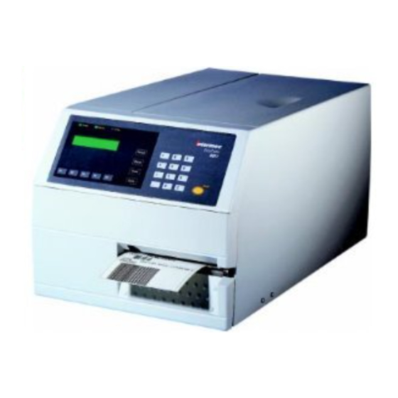
Intermec EasyCoder 501 SA Installation Instructions Manual
Industrial interface kit
Hide thumbs
Also See for EasyCoder 501 SA:
- User manual (29 pages) ,
- Installation instructions manual (7 pages) ,
- Installation instructions (5 pages)

Related Manuals for Intermec EasyCoder 501 SA


Summary of Contents for Intermec EasyCoder 501 SA
- Page 1 Installation Instructions P/N 1-960343-02 Edition 2 September 1998 EasyCoder 501/601 Industrial Interface Kit...
- Page 2 The input and output signals can be read or initiated by means of Intermec Fingerprint instructions. Thereby the printer can be used to control the external devices – or be controlled by them –...
- Page 3 Turn off the power and remove the power cord. Remove the communication cable from communication port "uart1:". Open the right hand door. Remove the eight Torx screws that hold the cover over the left part of the printer (see illustration below). Remove the cover. Cover 230V Communication Port "uart1:"...
- Page 4 CPU board do not come in contact with each other, which possibly may cause damage or short-circuiting. Fit the interface board assembly to the printer's rear plate from the inside as illustrated below using the same screws that held the removed cover plate.
- Page 5 INDUSTRIAL INTERFACE KIT, cont'd. Step-by-Step Installation Instructions, cont'd. Reassemble the printer in reverse order. Connect the communication cables to their respective connec- tors. Please refer to page 6 for pinout descriptions. Connect the power cord and turn on the power.
- Page 6 EasyCoder 501/601 – Installation Instructions INDUSTRIAL INTERFACE KIT, cont'd. Straps "uart3:" I/O connector Communication Port "uart3:" RS 232C: There are no straps for controlling the RS 232C interface on "uart3:". External +5V: External +5V ( max. 200 mA) can be made available on pin 16 by fitting a strap on P-1.
- Page 7 IN 104 IN 103/104 signals are controlled by means of PORTOUT (<nexp>) ON|OFF signals are read by means of PORTIN (<nexp>) Also see Intermec Fingerprint 6.13 Programmer's Manual. See example on next page See example on next page statements. functions.
- Page 8 EasyCoder 501/601 – Installation Instructions INDUSTRIAL INTERFACE KIT, cont'd. Connector Configuration, cont'd. Example of an IN port TIL193B Signal Min. Typical Input Voltage High 10V Input Voltage Low -1V Example of an OUT port REL1 OUT1 Max AC Load Breaking Capacity Current max.
- Page 9 Information in this manual is subject to change without prior notice and does not represent a commitment on the part of Intermec Printer AB. © Copyright Intermec PTC AB, 1998. All rights reserved. Published in Sweden. EasyCoder and Fingerprint are registered trademarks of Intemec Technologies Corp.