Advertisement
158EJ9771
12/1/03
10:01 AM
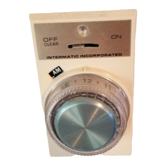
NTERMATIC
Instructions
Single Pole (Model EJ341C): For
lights controlled from one wall
switch.
Three Way (Model EJ343C): For
lights having two or more switches.
Manufactured under one or more of the following
patents:
4,349,748, 4,439,7488, 4,360,739, 4,379,245
4,439,688 and other patents pending.
INTRODUCTION
LIGHTING LOAD REQUIREMENTS
Use to control standard incandescent light bulbs or ther-
mally protected Class P ballast fluorescent lighting
(standard fluorescent) ONLY.
Load
Minimum
Incandescent
40 Watts
Fluorescent
40 Watts*
* Two standard 3 foot (30 Watt) bulbs or one standard 4
foot (40 Watt) bulb with rapid starter.
SPECIAL NOTES:
• Do not use with dimmers or photoelectric switch-
es.
• Do not use with "PAR" or "R" type outdoor flood
lamps or bulbs larger than 150 watts. Currents
generated during lamp burn-out could damage
the timer.
• Do not use to operate Mercury Vapor Lights,
Appliances, Radios, TV's, Stereos, etc.
• Your Timer generates radio energy and may in
rare cases cause radio or television interference.
Possible solutions include: readjusting the receiv-
er's antenna, plugging the receiver into a differ-
ent AC outlet or moving the receiver itself.
• The three way timer (EJ343) may not work if the
remote switch is more than 30 feet from the timer.
For such applications we recommend you use
model SS5C
CONTROLS AND INDICATORS
1.
Control lever
OFF-CLEAR
•
•
ON
•
2.
Pushbutton
•
•
•
3.
Indicator light
flashing
•
pulses
•
ON (steady)
•
OFF
•
•
•
•
•
4.
AM/PM
•
INSTALLATION
Your Timer replaces a standard light (toggle) switch. It
fits into a wall box easily and uses the same wires as
the switch you took out. If you can install a light switch,
you can install the Timer.
Single Pole (has two
black wires)
Tools needed:
Page 1
®
4,274,045,4,270,058,
4,344,000,
Maximum
400 Watts
500 Watts
3
1
4
2
no power to timer or controlled
light(s).
Clears the memory.
Timer is in operation or ready
for programming.
(time dial)
Push to turn lights on or off
manually.
Push twice quickly to switch
between automatic and manu-
al.
Turn to set automatic times, or
review automatic times.
(red)
Memory has been cleared,
timer is ready to be pro-
grammed.
Pulses when Pushbutton (time
dial) is turned during program-
ming or review.
Timer is programmed and in
automatic.
Control lever in OFF position.
Timer is in Manual Mode. (Push
button to turn lights on/off man-
ually.)
Timer is being programmed.
Timer is in review.
Light bulb burned out.
Reference for programming
and review.
Three Way (has one
red, blue and black
wire)
Supplied:
wire nuts (2 or 3)
outlet box
screws (2)
black control
panel screw (1)
control panel
screw (1)
jumper wire (1)
(three way only)
Step by Step Installation:
1.
TURN POWER OFF to the wall switch by removing
fuse or turning off circuit breaker.
2.
Remove switch plate and pull the existing switch out.
3.
Carefully pull
off the push-
button (time
dial) 3a and
remove
the
cover assem-
bly from timer
3b.
4.
Note: If the
old switch has a ground wire (normally a bare wire
connected to a green hex head screw) fasten it
securely to metal box or to timer metal bracket.
4a.
Single Pole Disconnect wires from old switch and
connect them to the Timer. Use wire nuts provided.
Go to step 6 below
4b.
Three Way Identify the
"common" wire. (The
common terminal nor-
mally has a different color screw, or is marked on
the old switch. The common wire is the power wire
and is usually black.)
Connect common wire
to black timer wire (use
wire nut) a.
Connect the other two
wires to the red b and
blue c timer wires (use wire nuts).
Three way wiring diagram for old wiring (using
the existing 3-way switch)
Line
Black
Blue
Red
EJ343C
Timer
Three way wiring diagram for new wiring or
when existing remote switch was a dimmer,
lighted or back wired switch (a standard single
pole switch is used for the remote switch).
Line
Black
Blue
Red
EJ343C
Timer
Single Pole Switch
5.
Three Way continued (at the second three way
switch)
Note: These instructions use trial-and-error to figure
out how to install the jumper wire.
1.
Be certain power is off.
2.
Remove switch plate and pull the existing
switch out.
Note: If the existing switch is a dimmer, illuminated
switch or back wire pressure terminal switch:
Replace it with a standard (single pole non-dimmer)
switch. Identify the "common" wire. Attach the com-
mon wire together with one of the other wires, to
either screw terminal. Attach the remaining wire to
the other screw terminal.
3.
Identify the "common" wire. (The common ter-
minal normally has a different color screw, or is
marked on the old switch. The common wire is
the power wire and is usually black.)
5b
4.
Loosen the common terminal just enough to
add one end of the jumper wire. Retighten.
5.
At either of the other two terminals 5a or 5b,
loosen the terminal just enough to add the
other end of the jumper wire. Retighten.
6.
Re-install the switch (do steps 6 - 8 below to
install the timer).
7.
If the timer and remote switch do not turn the
light on and off correctly, repeat steps 1 and 2
of 5 (above).
8.
Leave the jumper attached to the common ter-
minal. Switch the jumper to the other of the two
remaining terminals.
9.
Re-install the switch.
6.
Mount the timer into the wall box. Be careful not to
cut the wires on the edges of the box. Use 2 outlet
box screws provided.
3b
3a
c
a
b
Neutral
Install Jumper
Lamp
Existing
3-Way Switch
Neutral
Lamp
4
5a
Advertisement

Related Manuals for Intermatic EJ341C


Summary of Contents for Intermatic EJ341C
-
Page 1: Step By Step Installation
158EJ9771 12/1/03 10:01 AM NTERMATIC Instructions Single Pole (Model EJ341C): For lights controlled from one wall switch. Three Way (Model EJ343C): For lights having two or more switches. Manufactured under one or more of the following patents: 4,274,045,4,270,058, 4,349,748, 4,439,7488, 4,360,739, 4,379,245 4,439,688 and other patents pending. -
Page 2: Troubleshooting
If within one (1) year from the date of purchase, this product control lever fails due to a defect in material or workmanship, Intermatic Incorporated will repair or replace it free of charge. pushbutton The warranty does not apply to: (a) damage caused by acci-...