Table of Contents
Advertisement
Quick Links
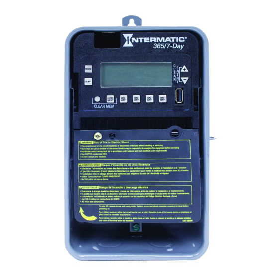
MODELS ET2745C, ET2745CR, ET2745CP
Installation and Setup Instructions
WARNING
Risk of Fire or Electric Shock
• Disconnect power at the circuit breaker(s) or disconnect switch(es) before installing or servicing.
• More than one circuit breaker or disconnect switch may be required to de-energize the equipment before servicing.
• For plastic enclosures, bonding between conduit connections is not automatic and must be provided as part of the installation.
• Installation and/or wiring must be in accordance with National and Local Electrical Code requirements.
• Use #14-#8 AWG wires, rated at least 105°C - COPPER conductors ONLY.
• If the power disconnect point is out of sight, lock it in the OFF position and tag it to prevent unexpected application power.
• Make sure there is no wire insulation under the terminal plate on the time switch connector. Firmly tighten terminal screws.
• For outdoor locations or wet locations (rain-tight), conduit hubs that comply with requirements of the UL514B (standard for fitting conduit and
outlet boxes) are to be used.
• Do not remove insulator that is covering terminals.
• Do NOT exceed maximum current carrying capacity.
• KEEP DOOR CLOSED AT ALL TIMES when not servicing.
NOTICE
• Do NOT touch circuit board components, contact can create a static discharge, which can damage these electronic components.
Description
This document explains the setup and configuration of the Intermatic ET2745
4-Circuit Electronic 365/7-Day Time Switch. The ET2745 time switch
automatically switches loads according to the according to the entered weekly
schedule. The time switch can support up to 48 fixed ON and 48 fixed OFF
events (96 total). Each fixed event can be applied to any combination of circuits
and days.
The time switch features an LCD and panel-mounted control buttons to set,
review, and monitor the time switch functions, including setting date and time,
schedule creation, enabling or disabling Daylight Saving Time (DST) and
configuring DST switchover dates.
Follow these instructions to complete the installation and programming of the
ET2745 time switch.
Federal Communications Commission (FCC) Notice for ET2000 Series Time Switches
This device complies with part 15 of the FCC rules. Operation of this device is subject to the following two conditions: (1) This device
may not cause harmful interference, and (2) This device must accept any interference, including interference that may cause
undesired operation. This equipment has been tested and found to comply with the limits for a Class A digital device, pursuant to
Part 15 of the FCC Rules. These limits are designed to provide reasonable protection against harmful interference when the
equipment is operated in a commercial environment. This equipment generates, uses and radiates radio frequency energy and, if
not installed and used in accordance with instructions, may cause harmful interference to radio communications. Operation of this
equipment in a residential area is likely to cause harmful interference that requires the user to correct at his or her own expense.
Electronic 4-Circuit
365/7-Day Time Switch
Shown in indoor/outdoor
lockable metal enclosure
With 100-Hour Backup
Advertisement
Table of Contents

Related Manuals for Intermatic ET2745


Summary of Contents for Intermatic ET2745
- Page 1 • Do NOT touch circuit board components, contact can create a static discharge, which can damage these electronic components. Description This document explains the setup and configuration of the Intermatic ET2745 4-Circuit Electronic 365/7-Day Time Switch. The ET2745 time switch automatically switches loads according to the according to the entered weekly schedule.
-
Page 2: Installation
Installation Snap out catch Tilt top forward Follow these instructions to install the time switch. Open the time switch enclosure door. Remove and retain the screw that secures the plastic insulator. Lift the left side of the plastic insulator and pivot away to expose the terminal strip. Press the latch at the top of the enclosure and pull out the mechanism from the enclosure. -
Page 3: Wiring Diagrams
Wiring Diagrams TIMER CIRCUIT 1 CIRCUIT 2 CIRCUIT 3 CIRCUIT 4 TIMER POWER POWER COM2 AC IN AC IN NO-1 COM1 NO-2 NO-3 COM3 NO-4 COM4 L2/N L2/N LOAD 1 LOAD 2 LOAD 3 LOAD 4 POWER TO TIMER 120/208/240/277 VAC (AUTO VOLTAGE, NO JUMPERS REQUIRED) 4 - INDIVIDUAL 120/277 VAC LOADS OUTPUT CONFIGURATION: IND - CIRCUIT 1 AND 2... -
Page 4: Programming Overview
Initial Setup The following sections provide instructions for the initial setup of the time switch. Setting The Output Configuration The time switch output configuration enables users to control multiple loads simultaneously (SIM), independently (IND), or with a 2-second pulse (PUL). Output circuits are configured in pairs; circuits #1 and #2 first, followed by circuits #3 and #4. In PUL mode, an ON event or manual override, causes circuit #1 to turn ON for two seconds, then OFF. - Page 5 If you select Then Go to step 8. NOTE: To view the start and end dates for a DST rule, press ENTER/ US2007 or MX1986 NEXT to scroll through the dates and then press MODE. Custom Press ENTER/NEXT. The screen displays a flashing MAR and 2ND. Go to step 4. Press + or - to select a starting month for customized DST and press ENTER/NEXT.
- Page 6 Setting Holidays There are 50 Holiday blocks that can be programmed along with a single schedule for each block. For each block there will be a start date and an end date. Within each block one scheduled “on” event and one “off” event can be programmed. Holidays are recognized by an H on the display.
- Page 7 Deleting (Clearing) an Event Fixed events can be deleted from the time switch. If you need to delete an event, follow this procedure. If necessary, press MODE to scroll through the different mode selections until SET FIXED ON/OFF EVENTS appear on the display.
-
Page 8: Specifications
LIMITED TWO-YEAR WARRANTY If within the warranty period specified, this product fails due to a defect in material or workmanship, Intermatic Incorporated will repair or replace it, at its sole option, free of charge. This warranty is extended to the original household purchaser only and is not transferable. This warranty does not apply to: (a) damage to units caused by accident, dropping or abuse in handling, acts of God or any negligent use;...