Intermatic EJ600 Series Installation And User Manual
Digital in-wall astronomic timer
Hide thumbs
Also See for EJ600 Series:
Advertisement
Quick Links
Spring Grove, Illinois 60081
www.intermatic.com
EJ600 Series
Digital In-Wall Astronomic Timer
Installation and User Guide
RATINGS
Operating Voltage
120 VAC, 60 Hz
Resistive
12 A
Incandescent
15 A (Single-gang)
12 A (Multi-gang)
Ballast (fluorescent)
500 VA
Motor
1/2 HP
Operating Temperature
32° F to 104° F (0° C to 40° C)
Dimensions
4 1⁄8" H x 1 3⁄4" W x 1 7⁄16" D
SAFETY SECTION
WARNING
Risk of Fire or Electric Shock
• Disconnect power at the circuit breaker(s) or disconnect
switch(es) before installing or servicing.
• Installation and/or wiring must be in accordance with
national and local electrical code requirements.
• Do not replace, recharge, disassemble, heat above 212° F
(100° C), crush, or incinerate the Lithium battery. Keep out
of reach of children.
• Do not use timer to control devices that could have
dangerous consequences due to inaccurate timing, such
as: sun lamps, saunas, heaters, slow cookers, appliances,
radios, televisions, stereos, etc.
• Only suitable for up to 3-gang installations.
NOTICE
• Dispose of product per local regulations for disposal of
Lithium batteries.
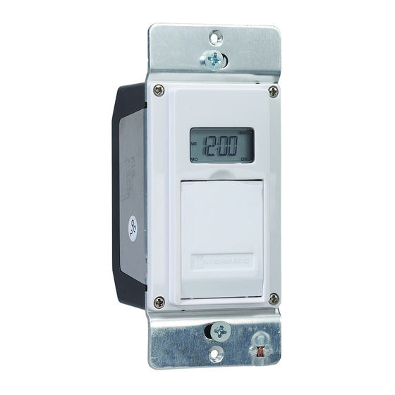
PRODUCT DESCRIPTION
The EJ600 Series In-Wall Timers provide
schedule customization with automatic dusk/
dawn, random, and Daylight Saving Time (DST)
programming options for up to 14 ON/OFF
events. The EJ600 Series are incandescent/
fluorescent/CFL/LED compatible and have a built-
in rechargeable, non-serviceable battery backup.
TIMER INTERFACE
Display
MODE button
NEXT/ON/OFF button
RESET button
M+/ZONE+/YEAR+ button
HOUR+/YEAR– button
DAY/DST button
INSTALLATION
1. Disconnect the power at the circuit breaker(s) or
disconnect switch(es).
2. Remove wall switches, if applicable.
7/16"
3. Strip the existing wire ends
to 7/16".
4. Wire the timer into the wall box.
• For an example of single-pole wiring,refer to
"Single-Pole Wiring".
• For an example of three-way wiring, refer to
"Three-Way Wiring".
• For other three-way wiring scenarios, go
to www.intermatic.com.
Single-Pole Wiring
A
B
C
D
E
A
Black — Connect to the hot (black) wire from the Power
Source
B
Blue — Connect to the other wire (black) from the load
C
Red — This wire is not used in single-switch installations.
Cap with a twist-on wire connector
D
Bare Copper — Connect to the supplied ground
E
White — Connect to the neutral wire from the wall
Three-Way Wiring
Note: The distance between the timer and the
remote switch must not exceed 100 feet.
A
B
C
D
E
A
Black — Connect to the wire removed from the "COMMON"
terminal of the switch being replaced
B
Blue — Connect to one of the other wires removed from the
switch being replaced. Record the wire color connected
to the blue wire for use during load-side installation
C
Red — Connect to the remaining wire removed from the switch
being replaced. Record the wire color connected to the
red wire for use during load-side installation
D
Bare Copper — Connect to the supplied ground
E
White — Connect to the neutral wire from the wall
Notes:
• Connect the timer on the line-side.
• Consult a qualified electrician:
– If you have trouble differentiating the wiring
colors for the building.
– When using a single-pole switch at the
remote location for new construction or to
replace a dimmer switch, a lighted switch,
or a three-way switch without screw
terminals.
Finalizing Installation
1. Make sure the twist-on wire connectors
(provided) are secure, then tuck the wires into the
timer wall box, leaving room for the timer.
2. Using the provided screws, secure the timer to
the wall box.
3. Cover the timer with the wall plate and secure
using the provided screws.
4. For three-way wiring, install the remote switch in
a wall box. Cover the switch with the wall plate
and secure.
5. Reconnect the power at the circuit breaker(s) or
disconnect switch(es).
TESTING THE TIMER
1. Make sure the timer displays MAN mode
during testing.
2. For three-way wiring, test the remote switch in
each of its two positions by pressing ON/OFF
several times. The timer should "click" and the
controlled light or device (load) should turn ON
or OFF.
3. For three-way wiring, if the timer clicks, but
the load does not operate:
a. Disconnect the power at the circuit
breaker(s) or disconnect switch(es).
b. Re-check your wiring and make sure
the load is functional.
c. Reconnect power at the circuit
breaker(s) or disconnect switch(es).
d. Retest.
4. For three-way wiring, if the timer clicks, but
the load only operates when the remote
switch is in one of its two positions, repeat
Step 3, a-d, paying close attention to the
wiring that connects with the red and blue
wires of the timer.
Note: Consult a qualified electrician if the switch
and timer fail to operate as intended.
When the controlled device turns ON and OFF
as appropriate, congratulations, the timer is
successfully installed and ready for programming!
NOTES
Read these notes before continuing with the timer
programming process.
• Your timer contains a built-in, non-replaceable,
rechargeable battery to maintain the date and
time of day information for at least 4 consec-
utive days of AC power interruption. All other
user settings are maintained indefinitely without
AC power. The built-in battery will fully charge
within a day of connection to AC power. After
an extended power outage, if the display is
flashing "12:00 AM", you will need to re-enter
the calendar, time, and day information.
• The CAL and CLK settings must be pro-
grammed before ON or OFF events can be set.
• Each ON or OFF setting is an event. Each event
must be programmed separately.
• All menus loop (repeat options when you get to
the end of the menu).
• When advancing to the next setting, the timer
automatically saves the data from the previous
screen regardless of setting changes. All set-
tings save automatically after five minutes.
Advertisement

Related Manuals for Intermatic EJ600 Series


Summary of Contents for Intermatic EJ600 Series
- Page 1 • All menus loop (repeat options when you get to Black — Connect to the hot (black) wire from the Power 5. Reconnect the power at the circuit breaker(s) or the end of the menu). The EJ600 Series In-Wall Timers provide Source disconnect switch(es). schedule customization with automatic dusk/ •...
-
Page 2: Initial Setup
• To offset the hour, press (three-way) switch jumper. programming of the EJ600 Series timers. ON/OFF events. HOUR+/YEAR-. is in one position or RAND • To offset the minutes, press Timer varies your programmed schedule +/- 20...