Table of Contents
Advertisement
Available languages
Available languages
Installation and User Instructions
WARNING
Risk of Fire or Electrical Shock
• Disconnect power at the circuit breaker(s) or disconnect switch(es) before
installing or servicing.
• Do NOT recharge, disassemble, heat above 100˚C (212˚F), crush, or incinerate the
non-replaceable Lithium battery. Keep out of reach of children.
• Do NOT use timer to control devices that could have dangerous consequences due
to inaccurate timing such as sun lamps, sauna, heaters and crock pots.
• Use #14 AWG wires, rated at least 90°C (194°F) - COPPER conductors ONLY.
• Installation and/or wiring must be in accordance with national and local electrical
code requirements.
Installing the Switch Timer
1. Turn off power at the circuit breaker or fuse and verify that the
power is OFF before wiring.
7/16”
2. Strip wire ends to 7/16”.
3. Make wire connections using the twist on
connectors provided.
4. Take one of these actions.
- If you have a single switch setup, then perform the
procedure “Installing the Timer with a Single Switch Setup”.
- If you have a 3-way switch setup, then perform the
procedure “Installing the Timer with a 3-way Switch Setup”.
Installing Switch Timer with a Single Switch Setup
1. Connect the LINE (Hot) wire from the wall to the black wire
from the switch timer with the twist
BLACK
WHITE
connectors provided.
2. Connect the LOAD wire from the wall to
the blue wire from the switch timer with
the twist connectors provided.
BLUE
3. NOTE: Cap the RED wire, which is
not used in single-switch installations,
with a twist connector.
RED
4. Connect the BARE COPPER wire
(capped, not connected)
to the grounding screw in the box
If a plastic box, connect to ground as supplied.
5. Connect the NEUTRAL (usually White) wire from the wall to the
WHITE wire from the timer.
6. Gently tuck wires into the timer wall box leaving room for the timer.
7. Using screws provided, mount the switch timer into the wall
box, then install the wall plate.
8. Turn the power back on at the service panel.
9. Go to “Intro to Programming: Read Before you Begin.”
Installing the Timer with a 3-Way Switch Setup
NOTE:
BLACK
WHITE
• The distance between switch timer and
remote switch must not exceed 100 feet.
• The timer must be installed in the wall box
that contains the LINE and Neutral
wires. The remote switch must be
BLUE
installed in the wall box that contains
the load wire (“WIRE C” in diagram 1).
RED
1. Using diagram #1 below, identify the
LINE wire previously connected to the COMMON terminal of
the old 3-way main switch.
2. Connect the BLACK wire from switch timer to the LINE wire,
using a twist connector.
3. Connect the other two wires from the old switch to the BLUE
and RED wires from the switch timer.
4. Connect the BARE COPPER wire to the grounding screw in the
box. If a plastic box, connect to ground as supplied.
5. Connect the NEUTRAL (usually White) wire from the wall to the
WHITE wire from the timer.
6. Using diagram #1 below, identify and remove wire “C” from the
“COMMON” terminal of your existing remote switch.
DIAGRAM 1:
LOAD
“COMMON” TERMINAL
TYPICAL
LINE
WIRE “A”
EXISTING
WIRE “C”
NEUTRAL
2-SWITCH
WIRE “B”
3-WAY
3-WAY
SETUP
REMOTE SWITCH
MAIN SWITCH
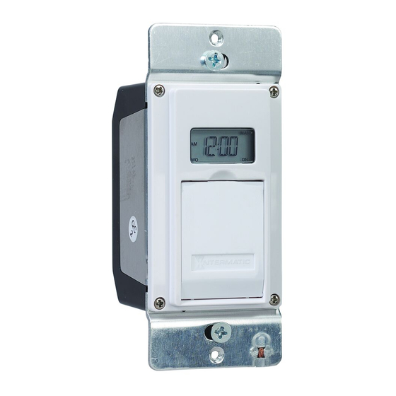
MODEL EJ600 SERIES
DIGITAL ASTRONOMIC TIMER
RATINGS:
• Single or multiple gang installations
• Resistive 12 A
• Tungsten 15 A (1800 W) Single Ganged, min 18 in
(295 cm
)
3
3
14 A, Single Ganged, minimum 12.5 in
(205 cm
)
3
3
12 A (1440 W) Multi-Ganged
• Ballast 500 VA
• Motor - 1/2 Hp
• All ratings 120 VAC, 60 Hz.
• A Neutral (WHITE) wire must be available to connect to timer.
7. Using diagram #2 remove and reconnect wires “B” and “C” to
the “COMMON” terminal of your remote switch, using the
supplied piece of jumper wire, if necessary.
NOTE: For new construction or to replace a dimmer switch, a
lighted switch, or a 3-way switch without screw terminals, a
single-pole switch should be used at the remote location, as
shown in diagram 3.
LOAD
DIAGRAM 2:
NEUTRAL
2-SWITCH SETUP,
WIRE “C”
WIRE “B”
LINE
BLUE
BLACK
TIMER INSTALL
NEUTRAL
TIMER
JUMPER
RE-USING EXISTING
WHITE
RED
WIRE “A”
REMOTE 3-WAY SWITCH
“COMMON” TERMINAL
3-WAY
NOT USED
REMOTE SWITCH
LOAD
DIAGRAM 3:
2-SWITCH SETUP,
NEUTRAL
LINE
WIRE “C”
WIRE “B”
BLUE
BLACK
TIMER INSTALL USING
NEUTRAL
NEW SINGLE-POLE
TIMER
JUMPER
WHITE
RED
REMOTE SWITCH
WIRE “A”
SINGLE-POLE
REMOTE SWITCH
NOTE: If the building’s wiring colors don’t allow you to tell wire “A”
from “B”, just pick one of the two wires and connect as if it is wire “B”.
After the installation is complete, if the controlled light or device will
not turn on properly, simply reverse wires “A” and “B”. See Steps 11
through 14 below for how to check.
8. Gently tuck wires into the timer wall box leaving room for the timer.
9. Using screws provided, mount the switch timer into the wall
box, then install the wall plate.
10. Turn the power back on at the service panel.
11. Make sure the switch timer displays “MAN” mode. Perform the
test in Step 12 with the remote switch in each of its 2 positions.
12. Press the NEXT/ON/OFF button on the switch timer several
times. Each time that you push the NEXT/ON/OFF button, the
controlled light or device (the “load”) should turn on or off. If so
proceed to Step 14.
13. If the controlled light or device does not turn on or off, take one
of these actions.
- If the timer clicks but the load does not operate, re-check
your wiring and make sure the load is functional.
- If the timer clicks but the load only operates when the remote
switch is in one of its 2 positions, you need to turn off the
power at the service panel, then reverse wires “A” and “B”.
You can reverse wires “A” and “B” at the remote switch wall
box, or you can reverse wires “A” and “B” where they
connect to the red and blue wires of the switch timer. Then
turn power back on at the service panel and repeat Step 12.
14. Verify that the controlled load turns on or off each time that the
remote switch is operated. Your timer is ready to be set.
15. Proceed to Intro to Programming.
Advertisement
Table of Contents

Related Manuals for Intermatic EJ600 Series


Summary of Contents for Intermatic EJ600 Series
- Page 1 MODEL EJ600 SERIES DIGITAL ASTRONOMIC TIMER Installation and User Instructions RATINGS: WARNING Risk of Fire or Electrical Shock • Single or multiple gang installations • Disconnect power at the circuit breaker(s) or disconnect switch(es) before • Resistive 12 A installing or servicing.
-
Page 2: Intro To Programming
Intro to Programming: Read Before You Begin Set Time of Day 1. If you have not already done so, press MODE • As you press the buttons to program, it will be helpful to have an overview of how they are organized. Press the MODE to scroll to CLK (clock) and a time. -
Page 3: Setting Sunset On/Specific Time Off
7. Take one of these actions: To Review or Revise Program Settings - If all the required programs are set, press MODE to exit and 1. Press MODE to scroll to PGM screen. go to Selecting AUTO, AUTO/RANDom, or MANual 2. -
Page 4: Troubleshooting Guide
LIMITED ONE-YEAR WARRANTY If within the warranty period specified, this product fails due to a defect in material or workmanship, Intermatic Incorporated will repair or replace it, at its sole option, free of charge. This warranty is extended to the original household purchaser only and is not transferable. This warranty does not apply to: (a) damage to units caused by accident, dropping or abuse in handling, acts of God or any negligent use;... -
Page 5: Caractéristiques Électriques
MODÈLE SÉRIE EJ600 MINUTERIE ASTRONOMIQUE NUMÉRIQUE Instructions d’installation et mode d’emploi CARACTÉRISTIQUES ÉLECTRIQUES : AVERTISSEMENT Risque d’incendie ou de choc électrique • Installations à circuit simple ou multiple • Débrancher l’alimentation au niveau des disjoncteurs ou des sectionneurs avant de procéder •... -
Page 6: Programmation
Introduction à la programmation : à lire avant de Régler l’heure de la journée commencer 1. Si ce n’est pas déjà fait, appuyer sur MODE pour avancer jusqu’à CLK (horloge) et l’heure. La première • Avant d’utiliser les touches de programmation, il est utile de savoir fois, 12:00 AM s’affiche en clignotant (Fig. - Page 7 Pour vérifier ou modifier les paramètres de 7. Effectuer l’une des actions suivantes : - Si tous les programmes requis sont configurés, appuyer sur MODE pour programmation quitter et aller à Sélectionner le mode AUTO, AUTO/RAND ou MAN. 1. Appuyer sur MODE pour avancer jusqu’à l’écran PGM. - Si un autre programme SNST ou SNUP (coucher/lever du soleil) doit être 2.
-
Page 8: Guide De Dépannage
GARANTIE LIMITÉE UN AN Si, dans la période de garantie spécifiée, ce produit tombait en panne dû à un vice de matériau ou de fabrication, Intermatic Incorporated le réparera ou le changera, à sa seule discrétion, et ce gratuitement. La présente garantie s’étend à l’acheteur final initial uniquement et n’est pas transférable. Cette garantie ne s’applique pas : (a) aux dommages au dispositif causés par un accident, une chute ou une mauvaise manipulation, une catastrophe naturelle ou une utilisation négligente;... -
Page 9: Clasificaciones
SERIE DE MODELOS EJ600 TEMPORIZADOR ASTRONÓMICO DIGITAL Instalación e instrucciones para el usuario ADVERTENCIA Riesgo de incendio o descarga eléctrica CLASIFICACIONES: • Desconecte la energía desde los disyuntores o desde los interruptores antes de realizar la • Instalaciones de una o múltiples entradas instalación o el mantenimiento. -
Page 10: Programación
Introducción a la programación: Lea antes de Ajuste de un programa ON/OFF (Encendido/apagado) comenzar en horas específicas • A medida que presiona los botones para programar, será útil contar con 1. Presione MODE (Modo) para desplazarse hasta la pantalla PGM ON una descripción general sobre cómo se organizan. - Page 11 Para revisar o modificar ajustes de programa 7. Tome una de estas medidas: - Si se ajustaron todos los programas que se requieren, presione 1. Presione MODE (Modo) para desplazarse hasta la pantalla PGM MODE (Modo) para salir y vaya a Selección de funcionamiento AUTO (Programa).
-
Page 12: Guía De Solución De Problemas
Este servicio de garantía está disponible ya sea (a) si se devuelve el producto al proveedor donde se compró la unidad o (b) si se completa una reclamación de garantía en línea en www. intermatic.com. Este producto tiene garantía de: Intermatic Incorporated, Customer Service 7777 Winn Rd., Spring Grove, Illinois 60081-9698. Para obtener servicios de garantía, ingrese a: http://www.Intermatic.com o llame al 815-675-7000.