
Related Manuals for Agilent Technologies G6600-90006


Summary of Contents for Agilent Technologies G6600-90006
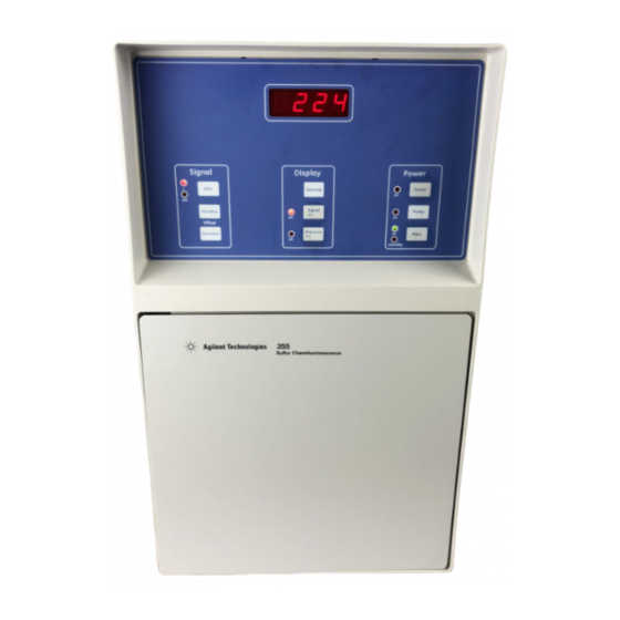
- Page 1 Agilent 355 Sulfur and 255 Nitrogen Chemiluminescence Detectors Operation and Maintenance Manual Agilent Technologies...
-
Page 2: Safety Notices
Notices © Agilent Technologies, Inc. 2007 No part of this manual may be reproduced in any form or by any means (including electronic storage and retrieval or transla- tion into a foreign language) without prior agreement and written consent from Agi- lent Technologies, Inc. - Page 3 Warnings English This symbol on the instrument indicates that the user should refer to the man- WA RN ING ual for operating instructions. Any operation requiring access to the inside of the equipment, could result in WA RN ING injury. To avoid potentially dangerous shock, disconnect from power supply before opening the equipment.
- Page 4 Ozone is a hazardous gas and a strong oxidant. Exposure to ozone should be minimized WA RN ING by using the instrument in a well-ventilated area and by venting the exhaust of the vac- uum pump to a fume hood. The ozone generator should be turned off when the instrument is not in use.
- Page 5 Español Cualquier operación que requiera acceso al interior del equipo, puede causar WA RN ING una lesión. Para evitar peligros potenciales, desconectarlo de la alimentación a red antes de abrir el equipo. Para protección contínua contra el peligro de fuego, sustituir el fusible por WA RN ING uno del mismo tipo y características.
- Page 6 Français Chaque opération à l'intérieur de l'appareil, peut causer du préjudice. Afin WA RN ING d'éviter un shock qui pourrait être dangereux, disconnectez l'appareil du réseau avant de l'ouvrir. Afin de protéger l'appareil continuellement contre l'incendie, échangez le fus- WA RN ING ible par un fusible du même type et valeur.
- Page 7 Deutsch Vor dem Öffnen des Gerätes Netzstecker ziehen! WA RN ING Für kontinuierlichen Schutz gegen Brandgefahr dürfen bei Sicherungswech- WA RN ING sel nur Sicherungen der gleichen Stärke verwendet werden! Dieses Symbol auf dem Gerät weist darauf hin, dass der Anwender zuerst das WA RN ING entsprechende Kapitel in der Bedienungsanleitung lesen sollte.
- Page 8 Italiano Qualsiasi intervento debba essere effettuato sullo strumento può essere WA RN ING potenzialmente pericoloso a causa della corrente elettrica. Il cavo di alimen- tazione deve essere staccato dallo strumento prima della sua apertura. Per la protezione da rischi da incendio in seguito a corto circuito, sostituire I WA RN ING fusibili di protezione con quelli dello stesso tipo e caratteristiche.
- Page 9 Dutch Iedere handeling binnenin het toestel kan beschadiging veroorzaken. Om ied- WA RN ING ere mogelijk gevaarlijke shock te vermijden moet de aansluiting met het net verbroken worden, vóór het openen van het toestel. Voor een continue bescherming tegen brandgevaar, vervang de zekering door WA RN ING een zekering van hetzelfde type en waarde.
- Page 10 The following symbols are used on the equipment: Caution - Refer to manual for operating instructions Atención - Ver documentación pertinente. Attention - Consultez les ocuments d'accomagnement. Vorsicht - Siehe beiliegende Unterlagen. Pericolo - Vedi documentazione allegata. Voorzichtig - Raadpleeg di bijehorende documentatie.
-
Page 11: Table Of Contents
Contents 1 Introduction 2 System Description Specifications Technical Information — 355 SCD Technical Information — 255 NCD Physical Specifications Theory of Operation Sulfur Chemiluminescence Detector Nitrogen Chemiluminescence Detector Dual Plasma Controller Description of Major Components Dual Plasma Burner Figure 1. Cross-Section of the Dual Plasma Burner for the 355 SCD Figure 2. - Page 12 3 Installation Overview Step 1: Selecting a Location Power Requirements Figure 10. Drawing of the Detector with Dual Plasma Burner and Controller Environmental Considerations Combustion Gas Requirements Step 2: Unpack and Inspect the Instrument Required Installation Tools Step 3: Set Up the Vacuum Pump Installing the Edwards RV5 Pump Oil-Sealed Vacuum Pump Figure 11.
- Page 13 Packed Columns and Columns with an Outside Diameter > 0.8 mm Step 10: Install the Transfer Line 4 Front Panel Controls and Initial Startup Detector Front Panel Controls Figure 21. Front Panel Controls Power Controls Display Output Controls Signal Controls Dual Plasma Controller Controls Figure 22.
- Page 14 6 Maintenance Pump Maintenance Table 3. Operating Life of Components for Edwards RV5 Vacuum Pump Cleaning the Detector Changing the Oil Mist Filter (RV5) Reaction Cell Cleaning Figure 23. Reaction Cell, PMT Housing and PMT Socket Figure 24. Reaction Cell Flow Sensor Calibration Detector Sensitivity Assembling the Dual Plasma Burner for Component Replacement with the SCD...
- Page 15 7 Troubleshooting Solving Detector Problems Power Problems Detector Fuse Vacuum Pump Fuse Dual Plasma Controller Fuses Table 4. Fuses for 100 V, 120 V and 230 V Versions of 355 SCD and 255 NCD Figure 47. Fuse Positions on the Power Supply Board Ozone Generation Problems Ozone Generator High Voltage Transformer...
- Page 16 Operation and Maintenance Manual...
-
Page 17: Introduction
If you are installing the 355 SCD or 255 NCD yourself, follow the installation procedures described in the following sections. If your instrument is already installed, turn to the Operation section to begin. Agilent Technologies... - Page 18 Operation and Maintenance Manual...
-
Page 19: System Description
Agilent 355 Sulfur and 255 Nitrogen Chemiluminescence Detectors Operation and Maintenance Manual System Description Specifications Theory of Operation Description of Major Components Agilent Technologies... -
Page 20: Specifications
Specifications Technical Information — 355 SCD Sensitivity Typical Selectivity Linearity Precision and Stability Ozone flow through the Post Ozone Restrictor Typical reaction cell pressure Typical Burner Pressure Typical Burner Temperature Typical Air Flow Rate Typical Hydrogen Flow Rate Signal Output Ranges Typical time to reach 800 °C from room temperature Typical safety shroud outside temperature... -
Page 21: Physical Specifications
Repeatability Gas flow through Ozone Generator Typical reaction cell pressure Typical Burner Pressure Typical Burner Temperature Typical Hydrogen Flow Rate Typical Oxygen Flow Rate Signal Output Ranges * Burner temperature 950 °C, 11 SCCM oxygen, and 6 SCCM hydrogen; 25 ppm N as nitrobenzene in toluene; 0.2 µL injection on column (HP 19095-121Z), n=7 for 3 hours;... - Page 22 Dual Plasma Controller Dual Plasma Burner Oil Sealed Vacuum Pump (RV5) Oil Free Dry Piston Pump Installation Category Pollution Degree Ambient Temperature Relative Humidity Normal Operating Environment Maximum Altitude Mains Supply Voltage Height: 5.0 in (12.7 cm) Width: 9.5 in (24.1 cm) Depth: 12.5 in (31.8 cm) Weight: 9.9 lbs (4.5 kg) Height: 12.3 in (31.2 cm)
-
Page 23: Theory Of Operation
Theory of Operation Sulfur Chemiluminescence Detector The Agilent model 355 Sulfur Chemiluminescence Detector (SCD) is a sulfur-selective detector for gas chromatography. Operation of the SCD is based on the chemiluminescence (light-producing reaction) from the reaction of ozone with sulfur monoxide (SO) produced from combustion of the analyte: Sulfur compound (analyte) SO + O A vacuum pump pulls the combustion products into a reaction cell at low... -
Page 24: Dual Plasma Controller
Dual Plasma Controller The Dual Plasma Controller provides all operational parameters of the Dual Plasma Burner except for the Detector base temperature. The Detector base temperature is controlled by circuitry in the GC. Parameters monitored or regulated by the Controller include Burner temperature, Burner temperature set-point, hydrogen and oxidant flow rates, and Burner pressure. -
Page 25: Description Of Major Components
Description of Major Components Dual Plasma Burner The Dual Plasma Burner consists of a tower assembly that contains an outer sheath for burn protection, a heating element, thermocouple, and combustion tubes. In the SCD, conversion of sulfur containing compounds to SO occurs within the ceramic reaction chamber housed in the Burner assembly and potentially interfering hydrocarbons are oxidized to CO the oxidant. -
Page 26: Figure 1. Cross-Section Of The Dual Plasma Burner For The 355 Scd
Figure 1 Cross-Section of the Dual Plasma Burner for the 355 SCD Operation and Maintenance Manual... -
Page 27: Dual Plasma Controller
Figure 2 Cross-Section of the Dual Plasma Burner for the 255 NCD Dual Plasma Controller The Dual Plasma Controller powers the Dual Plasma Burner and supplies its gases. Hydrogen and oxidant should be provided at 25 psig (1.72 bar) and the Controller is plugged into an appropriate AC electrical outlet. -
Page 28: Ozone Generator
temperature, hydrogen and oxidant flow rates, and Burner pressure. The temperature, actual pressure, oxidant and hydrogen flow rates are selected for display by rotation of a 4-position control knob. Power, valve operation, temperature within set-point range and fault conditions are indicated with LED illumination on the front display panel. -
Page 29: Figure 3. 355 Scd Left Side
1. Ozone Generator 2. High Voltage Transformer 3. Photomultiplier Tube Socket 4. Photomultiplier Housing 5. Reaction Cell Figure 3 355 SCD Left Side Operation and Maintenance Manual 6. Vacuum Line 7. Particulate Filter 8. Pre-Ozone Restrictor 9. Post-Ozone Restrictor 10. Pressure Transducer... -
Page 30: Figure 4. 355 Scd Right Side
ELECTRONICS OZONE PUMP 11. Amplifier Cable 12. HV Cable 13. PMT Amplifier 14. EMI Filter Figure 4 355 SCD Right Side TP12 HV/100 TP13 TP11 TP14 TP10 TP16 TP15 LOAD NEUT PUMP LOAD NEUT OZONE LINE NEUT 15. Fuses 16. Pressure Regulator 17. -
Page 31: Figure 5. 255 Ncd Left Side View
Figure 5 255 NCD Left Side View Operation and Maintenance Manual... -
Page 32: Figure 6. 255 Ncd Right Side View
Figure 6 255 NCD Right Side View Pressure Transducer Vacuum in the reaction cell is measured using a pressure transducer. The pressure of the reaction cell can be monitored from the front panel and will typically range from 5 to 10 torr depending on the type of vacuum pump used, condition of the chemical (ozone) trap, ceramic tube position and the condition of the combustion chamber. -
Page 33: Chemical Trap
• Collection and transfer of the combustion gases from the Burner to the reaction cell. • Transfer of ozone from the ozone generator to the reaction cell. • Reduction of non-radiative collisional quenching of the emitting species in the chemiluminescent reaction cell. The higher vacuum produced by the oil-sealed rotary pump facilitates a shorter residence time in the reaction chamber, and therefore reduces the incidence of collisional relaxation of the excited SO... -
Page 34: Ncd Photomultiplier Tube And Cooler
directly in front of the photomultiplier tube (PMT). A red cut-off filter between the reaction cell and the PMT selectivity transmits the light from the nitric oxide and ozone reaction. Efficient combustion in the ceramic tubes and the red cut-off filter eliminate interference from non-nitrogen containing analytes (sulfur dioxide, alkenes, olefins) that have chemiluminescence reactions with ozone. -
Page 35: Figure 7. Schematic For 355 Scd
Dual Plasma Burner Column Gas Chromatograph Figure 7 Schematic for 355 SCD Operation and Maintenance Manual Mass flow F.C. Mass flow F.C. Dual Plasma Controller Transfer Line 25 psig max 25 psig max 355 SCD Reaction Cell Vent... -
Page 36: Figure 8. Schematic For 255 Ncd, In Nitrogen Mode
Dual Plasma Burner Column Gas Chromatograph Figure 8 Schematic for 255 NCD, in Nitrogen Mode 25 psig max Mass flow F.C. Mass flow F.C. Dual Plasma Controller Transfer Line 25 psig max 255 NCD Reaction Cell Vent Operation and Maintenance Manual... -
Page 37: Figure 9. Schematic For 255 Ncd, In Nitrosamine Mode
Dual Plasma Burner Column Gas Chromatograph Figure 9 Schematic for 255 NCD, in Nitrosamine Mode Operation and Maintenance Manual 25 psig max Mass flow F.C. Mass flow F.C. Dual Plasma Controller Transfer Line *Or O , He, N 255 NCD Reaction Cell Vent... - Page 38 Operation and Maintenance Manual...
-
Page 39: Installation
Step 5: Install the Dry Compressed Air or O Supply Step 6: Install the Signal Output Cables Step 7: Install the Dual Plasma Burner Step 8: Install the Dual Plasma Controller Step 9: Install Column Connections Step 10: Install the Transfer Line Agilent Technologies... -
Page 40: Overview
Overview Installation and start-up of the Agilent 355 SCD or 255 NCD by a qualified Agilent Service technician is recommended. If you choose to install the detector yourself, carefully read all of this chapter prior to installation of the instrument. Although every reasonable safeguard against shipping damage has been taken, product damage may still occur due to excessive mishandling. -
Page 41: Step 1: Selecting A Location
Step 1: Selecting a Location The instrument should be placed on a clean, unobstructed surface approximately 22" (55 cm) deep by 10" (24 cm) wide that can support 44 pounds (19.9 kg) in addition to existing equipment. relationship between the major system components. To facilitate proper heat dissipation, an additional 1-2"... -
Page 42: Figure 10. Drawing Of The Detector With Dual Plasma Burner And Controller
Figure 10 Drawing of the Detector with Dual Plasma Burner and Controller Environmental Considerations The instrument should be operated in an environment which is comfortable for human habitation with reasonably constant temperature and humidity. Operation of the instrument at elevated temperatures (>30 °C) may result in an increased background noise from the photomultiplier tube. - Page 43 with air as the oxidant in the SCD and oxygen as the oxidant in the NCD. For the SCD, detector gases must be sulfur free (<1ppb) for proper Detector operation. In general, bottled air is preferred to “house” air from a compressor because compressors tend to generate lower quality air.
- Page 44 Secure all gas cylinders to an immovable structure or permanent wall. Store compressed WA RN ING gases in accordance with all safety codes. Wear eye protection when using compressed gas to avoid possible eye injury. WA RN ING Venting Gases During normal operation of the GC with the SCD, NCD, FID, other detectors and split/splitless inlet purge, some of the carrier gas and sample vents outside the GC.
-
Page 45: Step 2: Unpack And Inspect The Instrument
Step 2: Unpack and Inspect the Instrument Before unpacking boxes, inspect them for signs of physical damage. If damage is observed, photographs should be taken in order to make a claim with the carrier should any equipment damage be found. Check contents of boxes against the shipping documents. -
Page 46: Step 3: Set Up The Vacuum Pump
Step 3: Set Up the Vacuum Pump Initial connections require access to the rear of the Detector and the vacuum pump. Follow the installation instructions for either the RV5 Edwards pump or the oil-free dry piston pump, depending on your configuration. Exhaust gases from the pump should be vented to a fume hood to eliminate any potential WA RN ING hazard. - Page 47 Remove the drain plug and the bonded seal from the oil mist filter. The bonded seal looks like a metal washer with a black inner o-ring. Install the bonded seal to the oil mist filter drain adapter. The drain adapter looks like a drain plug with a small plastic nozzle.
- Page 48 The vacuum pump should be placed within approximately 3 feet of the Detector (elevation not important), in order to connect the vacuum hose from the back of the Detector to the chemical trap. A hose clamp should be placed over the hose, and the hose should be connected to the straight end of the chemical trap.
-
Page 49: Figure 11. Rv5 Oil-Sealed Vacuum Pump And Associated Traps (Front Side)
M ounting Bracket Edw ards Figure 11 RV5 Oil-Sealed Vacuum Pump and Associated Traps (Front Side) O il M ist Filter Figure 12 RV5 Oil-Sealed Vacuum Pump and Associated Traps (Back Side) Operation and Maintenance Manual Chem ical Trap Ballast control Power switch EDW ARDS C hem ical Trap... -
Page 50: Figure 13. Rv5 Oil- Sealed Vacuum Pump And Associated Traps (Top)
Gas ballast Inlet & valve Pump exhaust Retractable handle Chemical Oil fill caps Pum p inlet Trap Figure 13 RV5 Oil- Sealed Vacuum Pump and Associated Traps (Top) Sometimes water condensation and accumulation are visible in the exhaust line. This is NO TE normal. -
Page 51: Figure 14. Rv-5 Oil-S Ealed Vacuum Pump Exhaust Line
Figure 14 RV-5 Oil-S ealed Vacuum Pump Exhaust Line Setting the Gas Ballast Position (RV5) Set the mode selector halfway between the High Vacuum mode, the small symbol (see selector to the High Throughput mode, the large The RV5 vacuum pump and the Oil Drain Kit with ballast flow control ensure the vacuum pump operates continuously with a gas ballast flow. -
Page 52: Installing The Welch Dry Piston Vacuum Pump
• To select no gas ballast flow (not recommended), turn the restrictor plate so that none of the indentations are aligned with the indentation on the side of the oil return assembly. • To select low gas ballast flow, turn the restrictor plate so that the single indentation on the restrictor plate is aligned with the indentation on the side of the oil return assembly. - Page 53 Tighten the hose clamp located on the plastic tube and the elbow barb end of the Chemical Trap. Remove the plastic cap from the inlet end of the Chemical Trap. Taking the clear end of the vacuum hose and another hose clamp attach the vacuum hose to the inlet end of the Chemical Trap and tighten the hose clamp.
-
Page 54: Figure 15. The Welch Dry Piston Pump
Figure 15 The Welch Dry Piston Pump Figure 16 Oil Drain Kit with Ballast Control Turn the switch on the vacuum pump to the On position. Screws Restrictor Plate Indentation (Alignment Guide) Indentation (Low Ballast) Indentation (High Ballast) Operation and Maintenance Manual... - Page 55 Note the position of the oil level in the window after operating the pump for several hours. For the next several days of operation, recheck the oil level daily. If the oil level is increasing, water is accumulating in the oil reservoir. Confirm that the water vapor is properly being expelled from the oil mist filter.
-
Page 56: Step 4: Connect The Power Cord
Step 4: Connect the Power Cord Connect the pump power cord to the female socket on the back of the Detector (see Figure and this switch should be turned On. Do not connect to the AC power supply at this point in the installation procedure. AIR INLET RECORDER OUTPUT... -
Page 57: Step 5: Install The Dry Compressed Air Or O 2 Supply
Step 5: Install the Dry Compressed Air or O Connect a 1/8" OD Teflon (PFA) line fitted with a 1/8" brass Swagelok nut from the AIR INLET at the rear of the Detector (see compressed air or oxygen. The air regulator located inside the front door of the Detector should be set to approximately 3-6 psi. -
Page 58: Step 6: Install The Signal Output Cables
Step 6: Install the Signal Output Cables Signal output cables are available from Agilent as standard equipment and can be used with most data systems. Confirm that the output cable supplied is correct for your system. A standard cable fitted with two crimp lug connectors is supplied for use with most integrators, recorders or data systems. -
Page 59: Step 7: Install The Dual Plasma Burner
Step 7: Install the Dual Plasma Burner Remove the cover plates from the Detector area of the GC to expose the hole into the oven through which a Detector is normally mounted. If the GC has more than one available Detector position, pick the most convenient one. Prepare the GC by cutting the inside liner and top liner per that mounting fastener patterns will vary by GC manufacturer. -
Page 60: Step 8: Install The Dual Plasma Controller
Step 8: Install the Dual Plasma Controller Position the Controller such that the gas lines from the Burner can be easily attached to the back of the Controller. Connect the Controller to both a hydrogen source and an oxidant source, per Step 1. Connect the gas supplies to the 1/8"... -
Page 61: Step 9: Install Column Connections
Step 9: Install Column Connections The Burner operates under reduced pressure and there will be a slight vacuum on the end of the column. If a higher outlet pressure for the column outlet is desired, fused silica capillary restrictors may be attached to the end of the analytical column (both capillary and packed) prior to making the Detector connection. -
Page 62: Step 10: Install The Transfer Line
Step 10: Install the Transfer Line Connect the black transfer line (extending from the side of the Detector) to the top connector on the Burner and tighten with a 3/8" open-end and 7/16" open-end wrench (backing up the union on top of the Burner to prevent its position form slipping). -
Page 63: Front Panel Controls And Initial Startup
Agilent 355 Sulfur and 255 Nitrogen Chemiluminescence Detectors Operation and Maintenance Manual Front Panel Controls and Initial Startup Detector Front Panel Controls Detector Interface Setup Agilent Technologies... -
Page 64: Detector Front Panel Controls
Detector Front Panel Controls As illustrated in control, display output control, and power control. Each section is described below. All the front panel LEDs are red in the ON mode and darkened in the OFF mode except for POWER. This LED toggles green for ON and red for STANDBY. -
Page 65: Display Output Controls
Display Output Controls Signal Controls The SCD and NCD use analog amplifier circuitry for the measurement of the current produced by the photomultiplier tube. Two Front Panel Controls are used to adjust the output signal of the Detector. Operation and Maintenance Manual Turns ozone generator ON or OFF. -
Page 66: Dual Plasma Controller Controls
Dual Plasma Controller Controls The Agilent Dual Plasma Controller provides easy access to basic settings. Figure 22 Dual Plasma Controller Front Panel Oxidizer and Hydrogen Control Knobs Temperature Control Knob Selector Control Knob The baseline signal from the SCD and NCD can be adjusted from 0 to ±1% of the full scale recorder output using the offset control. -
Page 67: Initial Startup
Controller Status Lights Initial Startup Vacuum Test With the 1/8" Valco cap on the black PFA transfer line still in place and the air supply to the ozone generator off, set the internal air regulator to 0 psi (fully counterclockwise), and power on the SCD or NCD by plugging the power cord into the house power supply. - Page 68 Reaction cell pressure, with air to ozone generator OFF (0 psi setting on internal regulator) and transfer line capped: ___________________ torr Tighten connections if necessary and check to make sure pressure stabilizes in the expected region. If proper pressure is not obtained contact Agilent for assistance.
-
Page 69: Detector Interface Setup
Detector Interface Setup Initial Checkout Careful attention to eliminating leaks in the Detector interface will lead to better Detector sensitivity and easier troubleshooting if problems develop. Check that the gas connections have been made correctly and that they are tight. Plug the 3-prong connector for power on the Controller into a 100-volt, 50/60 Hz, 115-volt, 50/60-Hz or 230-volt, 50/60 Hz AC outlet. -
Page 70: Monitoring Oxidizer And Hydrogen Flow With The Dual Plasma Controller
Monitoring Oxidizer and Hydrogen Flow with the Dual Plasma Controller Hydrogen will flow to the Burner only if the temperature is above 325 °C and the pressure of the Burner is <575 torr. Turn ON the vacuum pump at the Detector and the power to the Dual Plasma Controller. -
Page 71: Operation
Agilent 355 Sulfur and 255 Nitrogen Chemiluminescence Detectors Operation and Maintenance Manual Operation Start-Up Procedure Detector Operation Typical Operating Conditions Detection Limits Instrument Shut-Down Special Operating Modes Agilent Technologies... -
Page 72: Start-Up Procedure
Start-Up Procedure Turn on the GC and set the carrier flow rate. Turn on the hydrogen and oxygen to the Dual Plasma Controller. Turn the Detector from STANDBY to ON. Press the PUMP button until the red LED illuminates. Make sure the vacuum pump is running. -
Page 73: Detector Operation
Detector Operation Detector Stability and Response The time required for system stabilization varies depending on the application, system cleanliness, presence of active sites and other factors. Useful results could be generated within 30 minutes of start-up, especially with a previously operated system. -
Page 74: Contaminated Gases
Contaminated Gases The use of clean gases for the 355 SCD is essential for optimal performance. High purity gases (99.999% pure or better) are advised. Sulfur and other contaminants from gases may accumulate in the column and bleed out over time desensitizing the tubes and causing elevated baselines. -
Page 75: Typical Operating Conditions
Typical Operating Conditions The Controller is calibrated at the factory for flow rates to deliver gas in sccm units. The following table summarizes the typical operating conditions: Table 1 Typical Operating Conditions Condition Detector Pressure (Torr) Dual Plasma Controller Pressure (Torr) Burner Temperature (°C) Hydrogen Flow Rate (sccm) Oxidant Flow Rate (sccm) -
Page 76: Detection Limits
Detection Limits The following table lists the detection limits which can be expected for typical chromatographic conditions, assuming proper operation of the Detector and chromatographic systems. Table 2 Expected Detection Limits for Chromatographic Conditions Type of Injection Liquid, Split 1:10 Liquid, Split 1:100 Liquid, On-column or splitless Liquid, Splitless... -
Page 77: Instrument Shut-Down
Instrument Shut-Down Daily Shutdown Toggle off the ozone generator. Turn off the air regulator (counter-clockwise), located inside Detector door. Toggle power to "stand-by." Leave the vacuum pump and Dual Plasma Controller operating at all times. Complete Shutdown Toggle off the ozone generator. Turn off the air regulator (counter-clockwise), located inside Detector door. -
Page 78: Special Operating Modes
Special Operating Modes Using the 255 NCD in Nitrosamine Mode By default, the 255 NCD is configured to detect nitrogen. To change from nitrogen to nitrosamine mode, first turn off and unplug the Controller. Remove the cover, find jumper P6 and the positions labelled High Setpoint and Low Setpoint located on the printed circuit board near the left front of the Controller. - Page 79 can be achieved by eliminating the lower plasma. This is accomplished by plugging the side port of the splitter fitting and teeing the air into the lower hydrogen line, much like the configuration used for Nitrosamine analysis as shown in Figure 9.
- Page 80 Operation and Maintenance Manual...
- Page 81 Reaction Cell Cleaning Flow Sensor Calibration Detector Sensitivity Assembling the Dual Plasma Burner for Component Replacement with the Assembling the Dual Plasma Burner for Component Replacement with the Tube Replacement for the SCD Tube Replacement for the NCD Agilent Technologies...
-
Page 82: Pump Maintenance
Pump Maintenance To maintain optimum performance of the Agilent 355 SCD and 255 NCD, routine replacement of the chemical trap (for ozone destruction), oil coalescing filter and oil (Edwards oil-sealed pump only) is necessary. Refer to Table 3 for the expected life span of each replacement part or material. It is beneficial to keep a maintenance log that tracks when maintenance is performed and any instrument or operational changes that might impact performance. -
Page 83: Cleaning The Detector
Cleaning the Detector You can clean the external housing of the Detector with a damp cloth using water or non-abrasive cleaners. Turn off power to the Detector and disconnect it from main power prior to cleaning. Do not spray liquids directly on the Detector. -
Page 84: Changing The Oil Mist Filter (Rv5)
Changing the Oil Mist Filter (RV5) The oil mist filter on the RV5 pump has two components: the charcoal odor filter and the oil coalescing filter element. To replace the filters, disassemble the oil mist filter assembly with the 4 mm long-handled allen wrench (provided). -
Page 85: Reaction Cell Cleaning
Reaction Cell Cleaning Over time, the reaction cell and UV pass filter (SCD) or IR pass filter (NCD) will develop a build-up of material which should be removed for optimum sensitivity. The cleaning schedule depends upon Detector use and the nature of the analyses;... -
Page 86: Figure 23. Reaction Cell, Pmt Housing And Pmt Socket
PMT HOUSING FILTER REACTION CELL Figure 23 Reaction Cell, PMT Housing and PMT Socket TRANSFER LINE Figure 24 Reaction Cell Use a 7/64" Allen wrench to remove the three mounting screws from the reaction cell. Slowly pull the reaction cell back from the PMT housing. The optical filter is located between the reaction cell and the PMT housing. - Page 87 Clean any deposits on the optical filter using a soft cloth or Kimwipe dampened with methanol or deionized (DI) water. Do not leave fingerprints or fibers on the cleaned filter. Deposits inside the reaction cell can be cleaned in the same manner, however, care must be taken to avoid bending the ozone inlet tube that extends into the cell.
-
Page 88: Flow Sensor Calibration
Flow Sensor Calibration The hydrogen and oxidant flow sensors installed in the Dual Plasma Controller have very good repeatability, but significant non-linearity. They have each been factory calibrated at the midrange flow rate (50 SCCM) using an NIST traceable flow meter. Over the typical operating range for the SCD, the flow sensors should produce accuracy of better than ±10% of reading. -
Page 89: Detector Sensitivity
Detector Sensitivity Detector sensitivity is an indicator reflecting the performance characteristics of a given system, and is a useful tool to determine when Detector maintenance is warranted. Sensitivity is typically reported as a minimum detection limit (MDL) as calculated from the following formula: Where Am't N/S (amount of nitrogen or sulfur) is the mass of nitrogen or sulfur in picograms that reaches the Detector, PktoPkNoise (peak-to-peak noise) is the measure of the noise (e.g. -
Page 90: Assembling The Dual Plasma Burner For Component Replacement With The Scd
Assembling the Dual Plasma Burner for Component Replacement with the The following procedure can be used to assemble the Dual Plasma Burner for use with the SCD or for replacement of Burner components, such as ceramic tubes. Refer to Slide the 0.066" internal diameter (I.D.) double taper ferrule onto the lower Burner tube. -
Page 91: Figure 26. Proper Ferrule Orientation To The Large Ceramic Tube
Figure 26 Proper Ferrule Orientation to the Large Ceramic Tube Figure 27 Large Ceramic Tube Properly Inserted into the Quartz Heater Assembly Position the upper ceramic tube into the long axis of the splitter fitting so that about 4 mm of it extends past the top of the fitting. Slide the 0.054" ID double tapered ferrule over the upper ceramic tube. -
Page 92: Figure 28. Orientation Of The Double Taper Ferrule
Figure 28 Orientation of the Double Taper Ferrule Figure 29 Positioning the Upper Tube in the Union Fitting Approximately 1.5 cm of the large ceramic tube should extend above the top of the quartz heater assembly. Slide a 1/4" Swagelok nut over the large ceramic tube and then also slide a 1/4"... -
Page 93: Figure 30. Tightening The Heater Swivel Nut
adapter, rotate this fitting so that the brazed H (opposite) from the oxidizer Inlet port. Figure 30 Tightening the Heater Swivel Nut Making sure that the Burner inlet fitting does not loosen, use a 1/2" wrench on a flat of the tapered union fitting and 9/16" wrench on the 1/4" Swagelok nut of the Burner adapter to tighten the tapered union fitting 1/4"... - Page 94 Carefully bend the H ferrule can be screwed into the side port of the splitter fitting. Tighten the connection of the H vertical flat of the splitter fitting and 1/4" wrench on the Valco nut. Make sure that no other connections have loosened or moved out of alignment, if so, reposition or retighten the fittings as needed.
-
Page 95: Assembling The Dual Plasma Burner For Component Replacement With The Ncd
Assembling the Dual Plasma Burner for Component Replacement with the The following procedure can be used to assemble the Dual Plasma Burner for use with the NCD or for replacement of Burner components, such as ceramic tubes. Refer to lower section of the NCD Burner is identical to the lower section of the SCD Burner. -
Page 96: Figure 33. Proper Ferrule Orientation To The Large Quartz Tube
Figure 33 Proper Ferrule Orientation to the Large Quartz Tube Figure 34 The Quartz Tube Properly Inserted into the Quartz Heater Assembly Insert the lower burner tube into the center of the quartz tube and finger tighten the heater swivel nut onto the tapered union fitting, then tighten an additional 1/4 turn making sure not to break the quartz tube. -
Page 97: Figure 35. Burner Assembly Detail
Using a 5/8" wrench on the heater swivel nut and a 1/2" wrench on one of the flats of the tapered union fitting, tighten the heater swivel nut one-quarter turn past finger-tight. Using a 5/16" wrench on the ¼" Burner adapter, rotate this fitting so that the brazed H (opposite) from the oxidizer Inlet port. -
Page 98: Tube Replacement For The Scd
Tube Replacement for the SCD The Burner has two combustion tubes that require replacement: the upper ceramic tube and the Large Ceramic Tube. Generally the tubes should be replaced only if sensitivity decreases. The “Troubleshooting” chapter provides additional information to assist in determining whether tube replacement may be necessary. -
Page 99: Figure 38. Positioning The Upper Tube In The Union Fitting
Figure 38 Positioning the Upper Tube in the Union Fitting Holding the splitter fitting, gently insert the upper ceramic tube into the large ceramic tube coaxially, to avoid placing stress on the fragile upper ceramic tube. Lower the splitter fitting into place to engage the threads of the 1/4"... -
Page 100: Figure 40. Large Ceramic Tube Properly Inserted Into The Quartz Heater Assembly
Figure 40 Large Ceramic Tube Properly Inserted into the Quartz Heater Assembly Approximately 1.5 cm of the large ceramic tube should extend above the top of the quartz heater assembly. Slide a 1/4" Swagelok nut over the large ceramic tube and then also slide a 1/4" ferrule over the tube (flat side on back of the nut). -
Page 101: Figure 42. Proper Alignment Of The Burner
nut of the Burner adapter to tighten the tapered union fitting one-quarter turn past finger-tight. Rotate the quartz heater assembly so that the thermocouple and heater leads are in the same plane and pointed in the same direction as the peg on the Burner inlet fitting. -
Page 102: Tube Replacement For The Ncd
Tube Replacement for the NCD The Burner has one quartz combustion tube that requires replacement. Generally the tube should be replaced only if sensitivity decreases. The “Troubleshooting” chapter provides additional information to assist in determining whether tube replacement may be necessary. Refer to page 46 for proper part nomenclature. -
Page 103: Figure 44. Large Quartz Tube Properly Inserted Into The Quartz Heater Assembly
Figure 44 Large Quartz Tube Properly Inserted into the Quartz Heater Assembly Insert the lower burner tube into the center of the quartz tube and finger tighten the heater swivel nut onto the tapered union fitting, then tighten an additional 1/4 turn making sure not to break the quartz tube. To begin the final tightening, use a 7/16"... -
Page 104: Figure 45. Ncd Tube Replacement Detail
Figure 45 NCD Tube Replacement Detail Figure 46 NCD Tube Replacement Detail The assembled Burner is now ready for re-installation on the GC, including column placement. Operation and Maintenance Manual... -
Page 105: Troubleshooting
Agilent 355 Sulfur and 255 Nitrogen Chemiluminescence Detectors Operation and Maintenance Manual Troubleshooting Solving Detector Problems Power Problems Ozone Generation Problems Response Problems Temperature Reading Problems Diagnosing General Problems Agilent Technologies... -
Page 106: Solving Detector Problems
Solving Detector Problems A basic understanding of the Detector helps one systematically diagnose and solve Detector problems. Many symptoms may be caused by more than one problem and these are the most difficult to troubleshoot. It should be pointed out, however, that analysis of sulfur or nitrogen compounds has traditionally been very difficult because of the inherent reactivity and instability of the compounds themselves. -
Page 107: Power Problems
Power Problems The first step in the determination of a power related problem is to verify power to the pump, Controller, and Detector itself. The inability to establish power may be as trivial as a blown fuse. Fuse requirements and positions on the Detector are indicated in see Repeated fuse failure is an indication of a more serious situation. -
Page 108: Table 4. Fuses For 100 V, 120 V And 230 V Versions Of 355 Scd And 255 Ncd
Remove the old fuses from the holder and replace with new fuses. If the Controller still does not power on after replacing the fuse, contact Agilent. Consult Table 4 Table 4 Fuses for 100 V, 120 V and 230 V Versions of 355 SCD and 255 NCD Detector Back Panel Main AC Power Detector... -
Page 109: Ozone Generation Problems
Ozone Generation Problems Following the verification of power to the instrumental components, the next step in tracing a problem is the determination of ozone production. With the ozone toggle off and the vacuum pump on, read the signal output on the front of the Detector. -
Page 110: Plugged Restrictor Lines
Plugged Restrictor Lines Plugged restrictor lines are verified by turning off the air/oxygen regulator located inside the door of the Detector and observing little or no change in the pressure as indicated on the regulator. The plug can be located in either the pre-ozone restrictor or the post-ozone restrictor (see Figure 3). -
Page 111: Response Problems
Response Problems Low or no response problems are the most difficult to troubleshoot on the Agilent SCD and NCD as they may arise from one source or a combination of sources. Primarily, response problems are due to combustion problems, and Burner integrity should be investigated first. -
Page 112: Temperature Reading Problems
Temperature Reading Problems Normally, the controller displays the burner temperature set-point. For diagnostic purposes, a switch in the controller (JP2) can be positioned to allow the display of the actual thermocouple temperature reading. When the actual temperature and set-point temperature agree, the heater indicator light on the front of the controller is illuminated. -
Page 113: Diagnosing General Problems
Diagnosing General Problems Table 5 Troubleshooting Detector Issues Problem Possible Cause No Response No ozone No Ozone Blown fuse No Ozone High Voltage Transformer and/or ozone generator is inoperative. No Ozone Ozone restrictor(s) plugged. No Response Hydrogen and/or air ran out. Measure flow rates. No Response Broken ceramic tube(s). - Page 114 Table 5 Troubleshooting Detector Issues (continued) Problem Possible Cause Low Response Contaminated ceramic tubes. Wandering Baseline Poor temperature control. Wandering Baseline Contamination in one of the Detector gases. Wandering Baseline Leak in the oxidizer line at the oxidizer inlet connection. Leak at weld of H fitting.
-
Page 115: Table 6. Troubleshooting Pump Issues
Table 5 Troubleshooting Detector Issues (continued) Problem Possible Cause Burner Fault Cycles. (off and Cracked tube. Burner Fault Cycles (off and Leak in Burner. Table 6 Troubleshooting Pump Issues Problem Possible Cause Pump is noisy High-pressure dry piston. Pump Doesn’t Start Dry piston seals have recently been changed. -
Page 116: Table 7. Troubleshooting Burner Issues
Table 7 Troubleshooting Burner Issues Problem Possible Cause Fuses Blow on Startup Shorted heater element. Low Sensitivity Leaks at ferrules or fittings. Low Sensitivity Improper gas flows. Low Sensitivity Broken ceramic tubes or ferrules High Pressure Low Sensitivity Improper column positioning. -
Page 117: Operation And Maintenance Manual
Index Calibration of Flow Sensor, Ceramic Tube Replacement, Column Insertion Distance, Detection Limits, Detector cleaning, display output controls, initial check, operating conditions, operation, power controls, schematic, NCD, schematic, NCD (nitrosamine mode), schematic, SCD, shut down, signal controls, start-up procedure, Dry Piston Pump installation, Dual Plasma Burner assembling for NCD,... - Page 118 Agilent Technologies © Agilent Technologies, Inc. Printed in USA, June 2007...