
Related Manuals for Icom IC-M3A


Summary of Contents for Icom IC-M3A
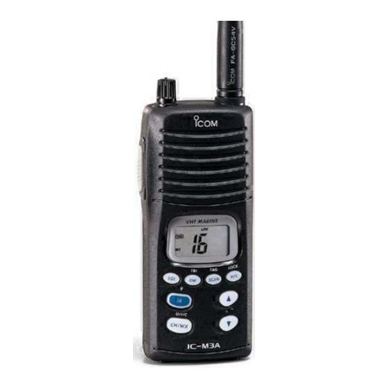
- Page 1 INSTRUCTION MANUAL VHF MARINE TRANSCEIVER iM3A This device complies with Part 15 of the FCC Rules. Operation is subject to the condition that this device does not cause harmful interference.
-
Page 2: Foreword
FOREWORD Thank you for purchasing this Icom product. The IC-M3A VHF MARINE TRANSCEIVER is designed and built with Icom’s su- perior technology and craftsmanship. With proper care this product should provide you with years of trouble-free operation. IMPORTANT READ ALL INSTRUCTIONS pletely before using the transceiver. -
Page 3: Cautions
CAUTIONS RWARNING! NEVER connect the transceiver to an AC outlet. This may pose a fire hazard or result in an electric shock. RWARNING! NEVER hold the transceiver so that the antenna is very close to, or touching exposed parts of the body, especially the face or eyes, while transmitting. -
Page 4: Table Of Contents
TABLE OF CONTENTS FOREWORD ... ii IMPORTANT ... ii EXPLICIT DEFINITIONS ... ii FEATURES ... ii CAUTIONS ... iii IN CASE OF EMERGENCY ... iii TABLE OF CONTENTS ... iv 1 OPERATING RULES ... 1 2 PANEL DESCRIPTION ... 2–4 I Front panel ... -
Page 5: Operating Rules
NOTE: Even though the IC-M3A is capable of operation on VHF marine channels 3, 21, 23, 61, 64, 81, 82 and 83, according to FCC regulations these simplex channels can- not be lawfully used by the general public in USA waters. -
Page 6: Panel Description
PANEL DESCRIPTION I Front panel q DUALWATCH /TRI-WATCH SWITCH [DW• • Starts dualwatch when pushed momentarily. • Starts tri-watch when pushed for 1 sec. • Stops dualwatch/tri-watch when either is ac- tivated. w SQUELCH SWITCH [SQL] • Push this switch, then set the squelch level with the UP/DOWN [ e CHANNEL 16 SWITCH [16 •... -
Page 7: I Top And Side Panels
I Top and side panels q PTT SWITCH [PTT] Push and hold to transmit; release to receive. w VOLUME CONTROL [OFF/VOL] Turns power ON and ad- justs the audio level. e ANTENNA CONNEC- Connects the supplied an- tenna. PANEL DESCRIPTION ï... -
Page 8: I Function Display
PANEL DESCRIPTION I Function display e r ty u BUSY CALL LOW q TRANSMIT INDICATOR Appears while transmitting. (p. 8) w BUSY INDICATOR Appears when receiving a signal or when the squelch level is set to the “OFF” position. (p. 8) e CALL CHANNEL INDICATOR Appears when the call channel is selected. -
Page 9: Basic Operation
I Channel selection D Channel 16 Channel 16 is the distress channel. It is used for establishing initial contact with another station and for emergency communications. Channel 16 is monitored during dualwatch/tri-watch. While standing by you are required to monitor channel 16. Push Channel 9 (Call channel) Channel 9 is the leisure-use call channel. -
Page 10: I Lock Function
There are 10 weather channels. These are used for monitor- ing weather channels from the NOAA (National Oceano- graphic and Atmospheric Administration) broadcasts. The IC-M3A can detect a weather alert tone on a selected weather channel while scanning. See the “SET mode items” on p. 12. -
Page 11: I Receiving And Transmitting
I Receiving and transmitting CAUTION: Transmitting without an antenna may damage the transceiver. q Rotate [OFF/VOL] clockwise to turn power ON, then set to the 10 o’clock position. - Use the squelch function to mute any audio noise if necessary. Refer to the previous page for details. -
Page 12: I Call Channel Programming
BASIC OPERATION I Call channel programming The call channel switch is used to select channel 9 by default, however, you can program your most often-used channels in each channel group for quick recall. q Push [CH/WX • ] for 1 sec. U/I/C several times to select the de- sired channel group (USA, INT,... -
Page 13: Dualwatch/Tri-Watch
I Description Dualwatch monitors channel 16 while you are receiving an- other channel; tri-watch monitors channel 16 and the call channel while receiving another channel. DUALWATCH/TRIWATCH SIMULATION Dualwatch Tri-watch • If a signal is received on channel 16, dualwatch/tri-watch pauses on channel 16 until the signal disappears. -
Page 14: Scan Operation
SCAN OPERATION I Scan types Scanning is an efficient way to locate signals quickly over a wide frequency range. The transceiver has a priority scan and a normal scan. In addition, weather alert functions is available for standby convenience. (p. 13) PRIORITY SCAN CH 01 CH 16... -
Page 15: I Setting Tag Channels
I Setting tag channels For more efficient scanning, add desired channels as tag channels or clear tag channels for unwanted channels. Chan- nels set as non-tag channels will be skipped during scanning. Tag channels can be assigned to each channel group (USA, CAN, INT) independently. -
Page 16: Set Mode
SET MODE I SET mode programming SET mode is used to change the conditions of 6 transceiver functions: the beep tone function, the automatic backlighting, weather alert function, normal/priority scan, scan resume timer and power save function. q Turn power OFF. w While pushing [SQL], turn power ON and continue push- ing [SQL] until “bP”... -
Page 17: Set Mode
D Weather alert function “AL” NOAA broadcast stations transmit weather alert tones before important weather announcements. When the weather alert function is turned ON, the transceiver detects the alert, then flashes the “ALT” indicator until the transceiver is operated. The previously selected (used) weather channel is checked periodically during standby or while scanning. -
Page 18: Battery Charging
BATTERY CHARGING I Installing batteries in the bat- tery case When using a battery case attached to the transceiver, install 6 AA(R6) size Ni-Cd or alkaline batteries as illustrated below. q Remove the battery case from the transceiver. w Install 6 × AA(R6) size Ni-Cd or alkaline batteries. •... -
Page 19: I Battery Cautions
ï Charging connections q Install 6 AA(R6) size Ni-Cd batteries into the battery case. w Turn the battery selector switch to the Ni-Cd position. e Connect the AC adapter (BC-131A) or optional cable (CP- 12L or OPC-254L) as shown below. - The charge indicator lights red. -
Page 20: Supplied Accessories
SUPPLIED ACCESSORIES AND ATTACHMENT Supplied accessories The following accessories are supplied: q Flexible antenna ......1 w Belt clip . -
Page 21: Troubleshooting
PROBLEM POSSIBLE CAUSE • The battery is exhausted. No power comes ON. • Bad connection to the battery pack. • Squelch level is too deep. No sound comes from • Volume level is too low. the speaker. • Speaker has been exposed to water. Transmitting is impos- •... -
Page 22: Channel List
CHANNEL LIST Channel number Frequency (MHz) CAN Transmit Receive 156.050 160.650 156.050 156.050 156.100 160.700 Guard Guard 156.150 160.750 156.150 156.150 156.200 160.800 04A 156.200 156.200 156.250 160.850 05A 156.250 156.250 156.300 156.300 156.350 160.950 07A 156.350 156.350 156.400 156.400 156.450 156.450 156.500 156.500 156.550 156.550... -
Page 23: Specifications And Options
I Specifications • GENERAL Frequency coverage : Transmit 156–157.5 MHz Receive 156–163 MHz Mode : FM (16K0G3E) Channel spacing : 25 kHz Current drain (at 7.2 V) : TX High (5 W) Max. audio Standby Power saved Frequency stability : ±10 ppm (–20°C to +60°C) Useable temperature range: –20°C to +60°C;... - Page 24 Count on us! A-5479D-1US-w Printed in Japan Copyright 1997 Icom Inc. 1-1-32 Kamiminami, Hirano-ku, Osaka 547-0003 Japan...