
Related Manuals for Icom IC-M37


Summary of Contents for Icom IC-M37
-
Page 1: Instruction Manual
INSTRUCTION MANUAL VHF MARINE TRANSCEIVER |M37 |M37E This device complies with Part 15 of the FCC rules. Operation is subject to the conditions that this device does not cause harmful interference. -
Page 2: Important
Thank you for choosing this Icom product. This product was designed and built with If your vessel requires assistance, contact Icom’ s state of the art technology and other vessels and the Coast Guard by craftsmanship. With proper care, this sending a distress call on Channel 16. -
Page 3: Fcc Information
CAUTION: Changes or modifications to reminds you that in the this transceiver, not expressly approved European Union, all electrical by Icom Inc., could void your authority and electronic products, to operate this transceiver under FCC batteries, and accumulators regulations. -
Page 4: Table Of Contents
■ Using the HM-213 ......23 OPERATING RULES ������������������������� 1 11 VHF MARINE CHANNEL LIST �������� 24 ACCESSORIES ��������������������������������� 2 ■ For IC-M37 (USA and EXP) and IC- ■ Supplied accessories ..... 2 M37E (AUS) ........ 24 ■ Attaching accessories ....2 ■... -
Page 5: Precautions
Shorting may contamination. damage not only the battery pack, but also • The use of Icom transceivers with any the transceiver. equipment that is not manufactured or CAUTION: DO NOT use harsh solvents approved by Icom. -
Page 6: Précautions
Icom avec des émetteurs-récepteurs environnements excessivement non-Icom ou des chargeurs non-Icom. poussiéreux. Cela pourrait endommager Seuls les blocsbatteries Icom sont testés l’émetteur-récepteur. et homologués pour être utilisés avec REMARQUE : NE PAS placer ou laisser des émetteurs-récepteurs Icom ou pour l’émetteur-récepteur en plein soleil ou... -
Page 7: Safety Training Information
Guidelines with regard to RF energy inch) away from the body when transmitting and electromagnetic energy levels and and only use the Icom belt-clips which are evaluation of such levels for exposure to listed on page 12 when attaching the radio to... -
Page 8: Infomation En Matiére De Sécurité
• Publication 447498 D03 de la FCC Icom illustrée à la p. 12, lorsque vous attachez KDB, «Evaluating Compliance with FCC la radio à votre ceinture, ou à autre chose, de Guidelines for Human Exposure to Radio façon à... -
Page 9: Operating Rules
NOTE: Even though the IC-M37/IC-M37E is capable of operation on VHF marine channels 21, 23, 81, 82, and 83, according to FCC regulations these simplex channels... -
Page 10: Accessories
ACCESSORIES ■ Supplied accessories Antenna Handstrap Belt clip Power adapter Battery pack Desktop charger (For Desktop charger) (With two screws) NOTE: Some accessories are not supplied, or the shape is different, depending on the transceiver version. ■ Attaching accessories D Antenna Connect the supplied antenna to the antenna connector. -
Page 11: D Battery Pack
ACCESSORIES D Battery pack To insert: Use a coin or standard screwdriver (1), and turn the screw counter clockwise one quarter turn (2). Screw position when Screw position when removing the battery cover. attaching the battery cover. Open the battery cover (1), and place the battery pack into the transceiver so it fits flat (2). -
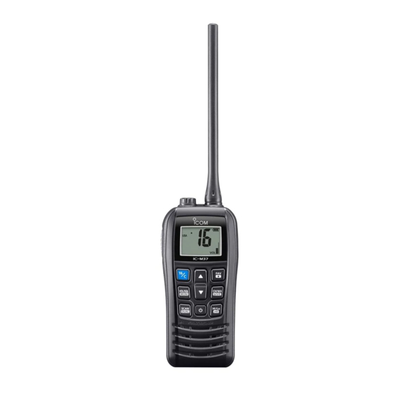
Page 12: Panel Description
PANEL DESCRIPTION ■ Front, top and side panels 5 SCAN/DUAL KEY [SCAN]/[DUAL] • Push to start or stop a scan. (p. 15) • Hold down for 1 second to start the Dual/Tri-watch mode. (p. 16) Function L While in Dualwatch, push to cancel display Dualwatch. -
Page 13: Function Display
PANEL DESCRIPTION ■ Function Display 8 VOLUME/SQUELCH LEVEL 2 3 INDICATOR • Number of bars shows the volume/ squelch level. • “SQL” blinks when adjusting the squelch level. (p. 12) • “VOL” blinks when adjusting the volume level. 9 SUB CHANNEL READOUT •... -
Page 14: Battery Charging
Icom dealer or distributor. long periods of time may cause the battery CAUTION: DO NOT expose the battery cells to rupture or catch fire. -
Page 15: Charging Caution
CAUTION: DO NOT charge the battery pack outside of the specified temperature range for BC-235: IC-M37/IC-M37E (AUS): 15˚C ~ 40˚C (59˚F ~ 104˚F) IC-M37E: 15˚C ~ 35˚C (59˚F ~ 95˚F) Otherwise, the charging time will be longer, but the battery will not reach a full charge. -
Page 16: Battery Charger
BATTERY CHARGING ■ Battery charger D Supplied battery charger D Optional battery charger Charging time: Approximately 4 hours for Charging time: Approximately 4 hours for the BP-296 the BP-296 CAUTION: NEVER connect the OPC- 2416 to a power source using reverse polarity. -
Page 17: Basic Operation
BASIC OPERATION ■ Selecting a channel D Regular Channel You can select a channel by pushing [▲] or [▼]. D Channel 16 Channel 16 is the distress and safety channel. It is used to establish the initial contact with a station, and for emergency communications. -
Page 18: Weather Channels And Weather Alert (For The Usa, Exp, And Aus Versions)
BASIC OPERATION ■ Weather channels and Weather Alert (For the USA, EXP, and AUS versions) The transceiver has 10 preset Weather channels. The transceivers are capable* of monitoring broadcasts from the National Oceanographic and Atmospheric Administration (NOAA). The transceiver automatically detects a Weather alert tone on the selected weather channel, or while scanning. -
Page 19: Receiving And Transmitting
BASIC OPERATION ■ Receiving and transmitting CAUTION: DO NOT transmit without an antenna. NOTE: Before using the transceiver for the first time, the battery pack must be fully charged for optimum life and operation. See Section 4 for battery charging. Push to select a channel. -
Page 20: Adjusting The Squelch Level
BASIC OPERATION ■ Adjusting the squelch level Squelch enables the audio to be heard only while receiving a signal that is stronger than the set level. A higher level blocks weak signals, so that you can receive only stronger signals. A lower level enables you to hear weak signals. -
Page 21: Setting The Call Channel
BASIC OPERATION ■ Setting the Call channel By default, a Call channel is set in each Channel Group. You can set your most often-used channel as your Call channel in each Channel Group, for quick recall. Hold down [16/C] for 1 second to select the Call channel. •... -
Page 22: Scan Operation
SCAN OPERATION You can find ongoing communication by scanning the Favorite channels. Scan is for the all transceiver versions except the HOL version. Before starting a scan: • Set the channels that you want to scan as Favorite channels. (p. 15) L Only the Favorite channels are scanned. -
Page 23: Favorite Channels
SCAN OPERATION ■ Favorite channels You can quickly recall often-used channels by setting them as Favorite channels. You can set Favorite channels in each Channel Group. D Setting/Clearing Push [▲] or [▼] to select the channel. Hold down [FAV] for 1 second to set or clear as a Favorite channel. -
Page 24: Dualwatch And Tri-Watch (Except The Hol Version)
DUALWATCH AND TRI-WATCH (Except the HOL version) ■ Description Dualwatch and Tri-watch are convenient to periodically check Channel 16 while you are operating on another channel. Dualwatch Tri-watch Call channel Operating CH 16 Operating channel channel CH 16 Periodically checks Channel Periodically checks Channel 16 and 16 while operating on another the Call channel while operating on... -
Page 25: Set Mode
SET MODE ■ Using the Set mode You can set seldom changed settings in the Set mode. You can customize the transceiver settings to suit your preference and operating style. While holding down [VOL/SQL], push [ ] to enter the Set mode. •... -
Page 26: Set Mode Items
SET MODE ■ Set mode items Auto Scan “ ” NOTE: The Set mode items contained in (Except the HOL version) the transceiver may be different, depending on the transceiver’s version or presettings. Turns the Automatic Scan function ON or OFF. Ask your dealer for details. - Page 27 SET MODE Low Battery Alarm “ ” CH Display “ ”/“ ”/“ ” Selects whether or not an alarm sounds Selects the number of digits to display the when the battery is low. A beep sounds channel number. You can select settings every time the battery indication is lower for each channel group.
-
Page 28: Atis Code
ATIS CODE (For only the HOL and FRG versions) The Automatic Transmitter Identification System (ATIS) ID consists of 10 digits. You can set and confirm the ID as shown below. NOTE: You can enter this initial code ONLY ONCE. After entry, only your dealer or distributor can change it. -
Page 29: Specifications And Options
SPECIFICATIONS AND OPTIONS ■ Specifications L All stated specifications are subject to change without notice or obligation. L Measurements made without an antenna. General IC-M37 IC-M37E IC-M37E (AUS) 156.025 ~ 156.000 ~ 156.025 ~ 157.425 MHz 161.450 MHz 157.425 MHz... -
Page 30: Options
SPECIFICATIONS AND OPTIONS ■ Specifications Receiver IC-M37 IC-M37E IC-M37E (AUS) Adjacent channel selectivity 70 dB (typical) 70 dB 65 dB Spurious response 70 dB (typical) 70 dB 65 dB Intermodulation 70 dB (typical) 68 dB 65 dB Hum and noise... -
Page 31: Using The Hm-213
SPECIFICATIONS AND OPTIONS ■ Using the HM-213 Alligator type clip To attach the speaker microphone to your shirt or collar. PTT switch Push to transmit. Release to receive. Microphone Speaker Turn the transceiver power OFF when connecting the HM-213. NOTE: •... -
Page 32: Vhf Marine Channel List
VHF MARINE CHANNEL LIST ■ For IC-M37 (USA and EXP) and IC-M37E (AUS) NOTE: When the “CH Display” is set to “4d” in the Set mode, the channel number is displayed in 4 digits. See page 19 for details. (Example: Channel 78A is displayed as “1078,” channel 78b is displayed as “2078.”) -
Page 33: For Ic-M37E (Except Aus)
VHF MARINE CHANNEL LIST ■ For IC-M37E (Except AUS) NOTE: When the “CH Display” is set to “4d” in the Set mode, the channel number is displayed in 4 digits. See page 19 for details. (Example: Channel 78A is displayed as “1078,” channel 78b is displayed as “2078.”) D International channels Frequency (MHz) Frequency (MHz) -
Page 34: Troubleshooting
TROUBLESHOOTING The transceiver does not turn ON� z The battery is exhausted. → Recharge the battery pack. (p. 8) z The battery pack is not correctly attached. → Correctly reattach the battery pack. (p. 3) Little or no sound comes from the speaker� z Squelch level is set too high. -
Page 35: Index
INDEX AD-138 ......22 Favorite channels Scan Antenna ......2 Clearing ....15 Normal ....14 AquaQuake....12 Selecting ....15 Priority ..... 14 ATIS Setting ..... 15 Starting ....15 ATIS code ....20 Float’n Flash ....19 Scan Timer ....18 Auto Scan .... - Page 36 A7494D-1EX-1 1-1-32 Kamiminami, Hirano-ku, Printed in Japan Osaka 547-0003, Japan © 2019 Icom Inc. May 2019...