Icom IC-M35 Instruction Manual
Hide thumbs
Also See for IC-M35:
- Instruction manual (36 pages) ,
- Service manual (30 pages) ,
- Instruction manual (11 pages)
Table of Contents
Advertisement
Quick Links
Download this manual
See also:
Service Manual
Advertisement
Table of Contents

Related Manuals for Icom IC-M35


Summary of Contents for Icom IC-M35
- Page 1 INSTRUCTION MANUAL VHF MARINE TRANSCEIVER iM35...
-
Page 2: Foreword
FOREWORD FEATURES ☞ Floating on water Thank you for choosing this Icom product. The IC-M35 vhf ma is designed and built with Icom’s state of the The transceiver floats on fresh or salt rine transceiver water even when the supplied acces- art technology and craftsmanship. -
Page 3: In Case Of Emergency
IN CASE OF EMERGENCY RECOMMENDATION If your vessel requires assistance, contact other vessels and CLEAN THE TRANSCEIVER THOROUGHLY WITH FRESH WATER after exposure to saltwater, and dry it before operat- the Coast Guard by sending a distress call on Channel 16. ing. -
Page 4: Precautions
Icom transceivers or Icom chargers. Only Icom than the BP-251 (option) or BP-252. Such a connection will battery packs are tested and approved for use with Icom ruin the transceiver. transceivers or charged with Icom chargers. Using third-party... - Page 5 • The use of Icom transceiver with any equipment that is not manufactured or approved by Icom. Icom, Icom Inc. and Icom logo are registered trademarks of Icom Incorporated (Japan) in Japan, the United States, the United Kingdom, Germany, France, Spain, Russia, Australia, New Zealand, and/or other countries.
-
Page 6: Table Of Contents
TABLE OF CONTENTS FOREWORD ..................i 5 SCAN OPERATION (Except Holland version) ....14–15 IMPORTANT ..................i ■ Scan types ................14 EXPLICIT DEFINITIONS ..............i ■ Setting TAG channels ............15 FEATURES ..................i ■ Starting a scan ...............15 IN CASE OF EMERGENCY ............. ii 6 DUALWATCH/TRI-WATCH (Except Holland version) ....16 RECOMMENDATION ............... -
Page 7: Operating Rules
OPERATING RULES D Priorities (2) OPERATOR’S LICENSE A Restricted Radiotelephone Operator Permit is the license • Read all rules and regulations pertaining to priorities and keep an up-to-date copy handy. Safety and distress calls most often held by small vessel radio operators when a radio is not required for safety purposes. -
Page 8: Supplied Accessories And Attachments
SUPPLIED ACCESSORIES AND ATTACHMENTS ■ Supplied accessories D Handstrap Handstrap Battery pack Battery charger Power adapter Pass the handstrap through (with 2 screws) (Different type or no the loop on the back side of power adapter is the transceiver as illustrated supplied depending at right. -
Page 9: Supplied Accessories And Attachments
SUPPLIED ACCESSORIES AND ATTACHMENTS Battery pack To remove the battery pack: NOTE: When removing or attaching the battery pack, use Turn the screw counter clockwise one quarter turn, then pull a coin or standard screwdriver to loosen or tighten the the battery pack in the direction of the arrow as shown below. -
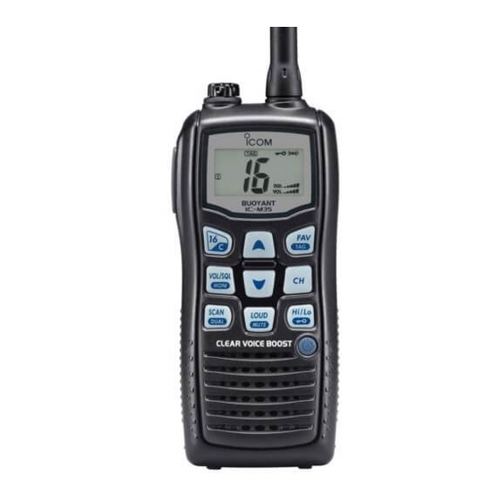
Page 10: Panel Description
PANEL DESCRIPTION ■ Front, top, side and rear panels q ANTENNA CONNECTOR (p. 2) Connects the supplied antenna. w SPEAKER-MICROPHONE CONNECTOR [SP MIC] (p. 25) Connects the optional external speaker-microphone. NOTE: Attach the [SP MIC] cap when the optional Function display speaker-microphone is not used. - Page 11 PANEL DESCRIPTION t VOLUME/SQUELCH/MONITOR KEY [VOL/SQL MONI] i FAVOURITE/TAG KEY [FAV TAG] ➥ Push to enter the volume adjustment mode and the ➥ Push this key to select the favourite (TAG) channels squelch adjustment mode. (pgs. 11, 12) with ignoring untagged channels in a channel group in sequence.
-
Page 12: Function Display
PANEL DESCRIPTION ■ Function display t LOCK INDICATOR (p. 13) Appears while the lock function is activated. y BATTERY INDICATOR Indicates remaining battery power. Indication Charging Battery level Full Middle No battery required blinks when the battery is over charged. blinks when the battery is exhausted. -
Page 13: Panel Description
PANEL DESCRIPTION !1 SQUELCH LEVEL INDICATOR !7 ATIS INDICATOR (p. 9) Shows the squelch level. “ATIS” appears when the channel group, which ATIS func- tion is activated, is selected. (Available with German and !2 VOLUME LEVEL INDICATOR Holland versions only.) ➥... -
Page 14: Basic Operation
BASIC OPERATION ■ Channel selection D Call channel IMPORTANT: Prior to using the transceiver for the first time, the battery pack must be fully charged for optimum Each regular channel group has separate leisure-use call life and operation. To avoid damage to the transceiver, channels. - Page 15 BASIC OPERATION D U.S.A., International, Canadian and ATIS channels The transceiver is pre-programmed with U.S.A.* , Inter- For German and Holland versions national, Canadian* and ATIS* channels. These channel groups may be specified for the operating area. q Push [CH] to select a regular channel. Push and hold for 1 sec.
-
Page 16: Receiving And Transmitting
BASIC OPERATION ■ Receiving and transmitting CAUTION: Transmitting without an antenna may damage IMPORTANT: To maximize the readability of your trans- mitted signal, pause a few sec. after pushing [PTT], hold the transceiver. the microphone 5 to 10 cm from your mouth and speak q Push and hold [ ] to turn power ON. -
Page 17: Call Channel Programming
BASIC OPERATION ■ Call channel programming ■ Adjusting the volume level The volume level can be adjusted with [VOL/SQL MONI] Call channel is used to access Channel 16 (default; may differ according to the version), however, you can program and [Y]/[Z]. the call channel with your most often-used channels in each q Push [VOL/SQL MONI] once to enter the volume adjust- channel group for quick recall. -
Page 18: Volume Loud Function
BASIC OPERATION ■ Volume loud function ■ Adjusting the squelch level The squelch level can be adjusted with [VOL/SQL MONI] The volume loud function can be activated temporarily by pushing [LOUD MUTE]. and [Y]/[Z]. In order to receive signals properly, as well as for the scan The function does not work when the volume level is 31. -
Page 19: Lock Function
BASIC OPERATION ■ Lock function ■ Automatic backlighting This function electronically locks all keys (except for [PTT], This function lights the function display and keys, and it is [VOL/SQL MONI], [LOUD MUTE], [Hi/Lo ] and [Y]/[Z]*) convenient for night-time operation. The automatic back- to prevent accidental channel changes and function access. -
Page 20: Scan Operation (Except Holland Version)
SCAN OPERATION (Except Holland version) ■ Scan types Set the TAG channels (scanned channels) before scanning. Scanning is an efficient way to locate signals quickly over a wide frequency range. The transceiver has priority scan and Clear the TAG for unwanted channels which inconveniently stop scanning, such as those for digital communications. -
Page 21: Setting Tag Channels
SCAN OPERATION ■ Setting TAG channels ■ Starting a scan For more efficient scanning, add the desired channels as Set the priority scan function, scan resume timer and auto TAG channels or clear TAG for unwanted channels. scan function in advance, using the set mode. (p. 18) Channels that are not tagged will be skipped during scan- q Push and hold [CH] for 1 sec. -
Page 22: Dualwatch/Tri-Watch (Except Holland Version)
DUALWATCH/TRI-WATCH (Except Holland version) ■ Description ■ Operation Dualwatch monitors Channel 16 while you are receiving q Select Dualwatch or Tri-watch in the set mode. (p. 19) on another channel; Tri-watch monitors Channel 16 and the w Select the desired channel. call channel while receiving another channel. -
Page 23: Set Mode
SET MODE ■ Set mode programming D Set mode operation Set mode is used to change the conditions of transceiver’s functions: Beep tone function, Priority scan function , Scan q Turn power OFF. † resume timer , Auto scan function , Dual/Tri-watch function w While pushing [VOL/SQL MONI], turn power ON to enter †... -
Page 24: Set Mode Items
SET MODE ■ Set mode items D Scan resume timer D Beep tone function “St” “bP” (Not available with Holland version) Select the key touch beep sound from ON or US, or turn The scan resume timer can be set as a pause (OFF) or sound OFF. - Page 25 SET MODE D Dual/Tri-watch function “dt” D Automatic backlighting “bL” (Not available with Holland version) This function is convenient for night-time operation. The This item can be set as Dualwatch or Tri-watch. (p. 16) backlight can be selected from ON and OFF. •...
-
Page 26: Set Mode
SET MODE D Power save function “PS” D Low fix function “LF” The power save function reduces current drain by deactivat- ( Appears only when the optional battery case is attached; not ing the receiver circuit for preset intervals. available with German version depending on the pre-setting.) •... -
Page 27: Battery Charging
If any of these conditions occur, contact your Icom dealer or R DANGER! NEVER use or leave battery pack in areas with distributor. -
Page 28: D Charging Caution
CAUTION: DO NOT charge the battery outside of the specific charge. The inside battery material will become weak after a temperature range: ±0˚C to +40˚C. Icom recommends charg- period of time, even with little use. The estimated number of ing the battery at +20˚C. The battery may heat up or rupture times you can charge the battery is between 300 and 500. -
Page 29: Supplied Battery Charger
BATTERY CHARGING ■ Supplied battery charger ■ Optional battery case D Charging connections When you would like to use the optional AAA(LR03) size battery case (BP-251), install the batteries as illustrated Do not charge batteries other than the BP-252. below. Be sure to observe the correct polarity. q Attach the BC-173 to a flat surface, such as a desk, if desired. -
Page 30: Optional Battery Charger
BATTERY CHARGING ■ Optional battery charger D Charging D BC-162 installation q Connect the power adapter as shown below. • To a desktop • To a wall w Insert the battery pack with/without the transceiver into Supplied screws Supplied screws the charger. -
Page 31: Optional Speaker-Microphone
OPTIONAL SPEAKER-MICROPHONE ■ HM-165 descriptions ■ Attachment Alligator type clip Turn power OFF before attaching the speaker-microphone. Then, insert the speaker-microphone’s connector into the To attach the speaker-microphone to your shirt or collar, etc. [SP MIC] connector and carefully screw it tight, as shown below. -
Page 32: Troubleshooting
TROUBLESHOOTING PROBLEM POSSIBLE CAUSE SOLUTION REF. The transceiver does not turn • The battery is exhausted. • Recharge the battery pack. p. 23 • The battery pack is not attached cor- • Attach the battery pack correctly. p. 3 rectly. No sound comes from the •... -
Page 33: Vhf Marine Channel List
VHF MARINE CHANNEL LIST • International channels Frequency (MHz) Frequency (MHz) Frequency (MHz) Frequency (MHz) Frequency (MHz) Frequency (MHz) Transmit Receive Transmit Receive Transmit Receive Transmit Receive Transmit Receive Transmit Receive 160.650 156.550 157.050 161.650 156.125 160.725 156.625 156.050 156.550 156.625 157.125 161.725... - Page 34 VHF MARINE CHANNEL LIST • USA channels (for U.K. and China versions) Frequency (MHz) Frequency (MHz) Frequency (MHz) Frequency (MHz) Frequency (MHz) Frequency (MHz) Transmit Receive Transmit Receive Transmit Receive Transmit Receive Transmit Receive Transmit Receive 156.050 156.050 156.600 157.100 156.225 156.600 157.100...
-
Page 35: Vhf Marine Channel List
VHF MARINE CHANNEL LIST • Canadian channels (China version only) Frequency (MHz) Frequency (MHz) Frequency (MHz) Frequency (MHz) Frequency (MHz) Frequency (MHz) Transmit Receive Transmit Receive Transmit Receive Transmit Receive Transmit Receive Transmit Receive 156.600 156.600 Rx only 161.650 156.075 156.075 156.625 156.625... -
Page 36: Specifications
SPECIFICATIONS D GENERAL D RECEIVER • Frequency coverage : Transmit 156.000–161.450 MHz • Receive system : Double-conversion superhetero- Receive 156.000–163.425 MHz dyne • Mode : FM (16K0G3E) • Sensitivity (20 dB SINAD) : –2 dBµ emf typical • Channel spacing : 25 kHz •... -
Page 37: Options
Battery case for 5 × AAA (LR03) alkaline cells. ance when used with an Icom transceiver. Icom is not responsible for the destruction or damage to an Icom Output power level : 2 W at high (Depends on the pre-setting for transceiver in the event the Icom transceiver is used with equipment German version.) -
Page 38: Information
INFORMATION ■ Country code list ■ Disposal • ISO 3166-1 The crossed-out wheeled-bin symbol on your product, literature, or packaging reminds you Country Codes Country Codes that in the European Union, all electrical and 1 Austria 18 Liechtenstein electronic products, batteries, and accumulators 2 Belgium 19 Lithuania (rechargeable batteries) must be taken to... - Page 39 MEMO...
- Page 40 < Intended Country of Use > A-6711H-1EU-r Printed in Japan 2008–2016 Icom Inc. © 1-1-32 Kamiminami, Hirano-ku, Osaka 547-0003, Japan Printed on recycled paper with soy ink.