Icom IC-F121 Instruction Manual
Uhf/vhf transceiver
Hide thumbs
Also See for IC-F121:
- Instruction manual (24 pages) ,
- Price list (158 pages) ,
- Service manual (36 pages)
Table of Contents
Advertisement
Advertisement
Table of Contents

Related Manuals for Icom IC-F121


Summary of Contents for Icom IC-F121
- Page 1 INSTRUCTION MANUAL VHF TRANSCEIVER iF111 iF121 UHF TRANSCEIVER iF211 iF221...
-
Page 2: Important
fire or electric shock. Icom, Icom Inc. and the logo are registered trademarks of Icom Incorporated (Japan) in the United states, the United Kingdom, Germany, France, Spain, Russia and/or other countries. SmarTrunk II™ is a trademark of the SmarTrunk Systems, Inc. -
Page 3: Table Of Contents
For U.S.A. only CAUTION: Changes or modifications to this transceiver, not ex- pressly approved by Icom Inc., could void your authority to operate this transceiver under FCC regulations. TABLE OF CONTENTS IMPORTANT ... -
Page 4: Panel Description
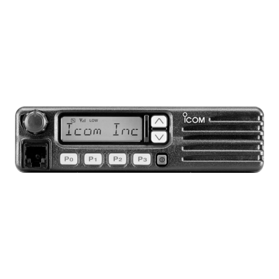
PANEL DESCRIPTION I Front panel q AF VOLUME CONTROL KNOB Rotate the knob to adjust the audio output level. • Minimum audio level is pre-programmed. w FUNCTION DISPLAY Displays a variety of information, such as an operating channel number/name, 5-tone code, DTMF numbers and audible condition, etc. -
Page 5: I Function Display
t DEALER-PROGRAMMABLE KEYS [P0] to [P3] Desired functions can be programmed independently by your dealer. y MICROPHONE CONNECTOR Connect the supplied microphone or optional DTMF micro- phone for SmarTrunk II operation here. NEVER connect non-specified microphones. The pin assignments may be different and the transceiver may be damaged. -
Page 6: I Programmable Function Keys
The following functions can be assigned to [P0], [P1], [P2], [P3], [ ] and [ ] programmable function keys. Consult your Icom dealer for details concerning your trans- ceiver’s programming. In the following explanations, programmable function names are bracketed. The specific switch used to activate the func- tion depends on programming. - Page 7 ¡ ¡ SCAN START/STOP KEY Push this key to start scanning; and push again SCAN A to stop. SCAN B NOTE: Place the microphone on hook to start scanning. Take the microphone off hook to stop scanning. ¡ ¡ SCAN TAG KEY Adds or deletes the selected channel to the scan group.
- Page 8 PANEL DESCRIPTION ¡ ¡ OUTPUT POWER SELECTION KEYS Select the transmit output power temporarily, or permanently, depending on the pre-setting. • Contact your dealer for the output power level for each selection. ¡ ¡ TALK AROUND KEY Turns the talk around function ON and OFF. •...
- Page 9 ¡ ¡ SCRAMBLER KEY ➥ Push and hold to turn the voice scrambler func- SCRM tion ON. ➥ Push this key to turn the voice scrambler func- tion OFF. NOTE: • The optional UT-109 (#02) or UT-110 (#02) VOICE SCRAMBLER UNIT is required. –...
-
Page 10: Operation
OPERATION I Turning power ON q Push [ ] to turn the power ON. w If the transceiver is programmed for a start up passcode, input the digit codes as directed by your dealer. • The keys in the table below can be used for password input: •... -
Page 11: I Receiving And Transmitting
I Receiving and transmitting RECEIVING: q Push [ ] to turn the power ON. w Push [ ] and [ ] to select a channel. e When receiving a call, adjust the audio output level to a comfortable listening level. TRANSMITTING: r Take the microphone off hook. -
Page 12: D Tx Code Channel Selection
OPERATION D TX code channel selection If the transceiver has a [TX CH] key, the display can be tog- gled between the operating channel number (or name) and TX code channel number (or name). When the TX code channel number (or name) is displayed, the [ select the TX code channel. -
Page 13: D User Set Mode
D User set mode User set mode is accessed at power ON and allows you to set seldom-changed settings. In this case you can “cus- tomize” transceiver operation to suit your preferences and operating style. Entering the user set mode: q While pushing and holding [ ] and [ to enter user set mode ON, allowing you to set seldom-... -
Page 14: Optional Smartrunk
OPTIONAL SmarTrunk II™ OPERATION I SmarTrunk II™ and conventional modes This transceiver is capable of SmarTrunk II™ functions. The optional UT-105 allows communication in conventional channels or SmarTrunk II™ channels. Select a channel bank for SmarTrunk II™ before trunking operation. •... -
Page 15: D Emergency Call
D Terminating a call After completing a call, push [#] to disconnect (hang up). IMPORTANT!: If one person in the conversation termi- nates a call, all participants will be cut off. D Last number re-dial Push [M] 2 times to automatically re-dial the last called num- ber. -
Page 16: Connection And Maintenance
CONNECTION AND MAINTENANCE I Rear panel and connection Antenna To the antenna connector Optional cable (OPC-617) Optional speaker (SP-22) R C A U T I O N ! N E V E R r e- move the fuse-holder from the DC power cable. black: Battery NEVER connect to... -
Page 17: I Supplied Accessories
q ANTENNA CONNECTOR Connects to an antenna. Contact your dealer about an- tenna selection and placement. w MICROPHONE HANGER Connect the supplied microphone hanger to the vehicle’s ground for microphone on/off hook functions. (See p. 2) e DC POWER RECEPTACLE Connects to a 12 V DC battery. -
Page 18: I Mounting The Transceiver
CONNECTION AND MAINTENANCE I Mounting the transceiver The universal mounting bracket supplied with your transceiv- er allows overhead mounting. • Mount the transceiver securely with the 4 supplied screws to a thick surface which can support more than 1.5 kg. Flat washer Spring washer When using... -
Page 19: I Optional Ut-109 Or Ut-110 Installation
I Optional UT-109 or UT-110 installation q Turn the power OFF, then disconnect the DC power cable. w Unscrew the 4 cover screws, then remove the bottom cover. e Cut the pattern on the PCB at the TX mic circuit (MIC) and RX AF circuit (DISC) as shown below. -
Page 20: I Antenna
CONNECTION AND MAINTENANCE I Antenna A key element in the performance of any communication sys- tem is an antenna. Contact your dealer about antennas and the best places to mount them. I Fuse replacement A fuse is installed in the supplied DC power cable. If a fuse blows or the transceiver stops functioning, track down the source of the problem if possible, and replace the damaged fuse with a new rated one. -
Page 21: Options
OPTIONS SP-22 EXTERNAL SPEAKER Compact and easy-to-install. Input impedance : 4 Ω Max. input power : 5 W HM-100TN DTMF microphone. SM-25 Desktop microphone. UT-105 SmarTrunk II Logic Board Provides SmarTrunk II capabilities. UT-108 DTMF DECODER UNIT Provides pager and code squelch capabilities. UT-109/UT-110 (#02) VOICE SCRAMBLER UNIT •... -
Page 22: Safety Training Information
You can cause the radio to transmit by press- ing the “PTT” switch. Electromagnetic Interference/Compatibility During transmissions, your Icom radio generates RF energy that can possibly cause interference with other devices or systems. To avoid such interference, turn off the radio in areas where signs are posted to do so. - Page 23 MEMO...
- Page 24 Count on us! A-6235H-1EX Printed in Japan 1-1-32 Kamiminami, Hirano-ku, Osaka 547-0003 Japan © 2002 Icom Inc.