Icom IC-F25 Instruction Manual
Uhf/vhf transceiver
Hide thumbs
Also See for IC-F25:
- Instruction manual (48 pages) ,
- Service manual (32 pages) ,
- Servise manual (8 pages)
Table of Contents
Advertisement
Advertisement
Table of Contents

Related Manuals for Icom IC-F25


Summary of Contents for Icom IC-F25
- Page 1 INSTRUCTION MANUAL VHF TRANSCEIVER iF15/S UHF TRANSCEIVER iF25/S...
-
Page 2: Explicit Definitions
READ ALL INSTRUCTIONS carefully and completely before using the transceiver. SAVE THIS INSTRUCTION MANUAL— This instruction manual contains important operating instructions for the IC-F15/ F15S and IC-F25/F25S VHF TRANSCEIVER UHF TRANSCEIVER EXPLICIT DEFINITIONS WORD DEFINITION Personal injury, fire hazard or electric shock RWARNING may occur. -
Page 3: Precaution
Exposing the inside of the transceiver to water will result in serious damage to the transceiver. The use of non-Icom battery packs/chargers may impair transceiver performance and invalidate the warranty. Icom, Icom Inc. and the... -
Page 4: Table Of Contents
TABLE OF CONTENTS FOREWORD ……………………………………………………………… i EXPLICIT DEFINITIONS ………………………………………………… i OPERATING NOTES ……………………………………………………… i PRECAUTION …………………………………………………………… ii TABLE OF CONTENTS ………………………………………………… iii 1 ACCESSORIES ……………………………………………………… 1–5 ‘ Supplied accessories………………………………………………… 1 ‘ Accessory attachments ……………………………………………… 2 2 PANEL DESCRIPTION …………………………………………… 6–11 ‘... -
Page 5: Supplied Accessories
ACCESSORIES I Supplied accessories The following accessories are supplied: Qty. q Flexible antenna ........1 w Battery pack . -
Page 6: Accessories
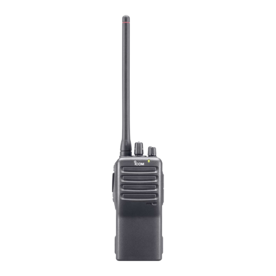
ACCESSORIES I Accessory attachments D Flexible antenna Connect the supplied flexible an- tenna to the antenna connector. CAUTION: • NEVER HOLD by the antenna when carrying the transceiver. • Transmitting without an antenna may damage the transceiver. -
Page 7: Battery Pack
ACCESSORIES ï Battery pack To attach the battery pack: Slide the battery pack on the back of the transceiver in the direc- tion of the arrow (q), then lock it with the battery release button. • Slide the battery pack until the battery release button makes a ‘click’ sound. -
Page 8: Jack Cover
ACCESSORIES ï Jack cover Attach the jack cover when the optional speaker-microphone is not used. To attach the jack cover: To detach the jack cover: q Attach the jack cover to the q Unscrew the screws with a [SP MIC] connector. phillips screwdriver. - Page 9 ACCESSORIES D Belt clip To attach the belt clip: q Release the battery pack if it is attached. w Slide the belt clip in the direction of the arrow until the belt clip is locked and makes a ‘click’ sound. To detach the belt clip: q Release the battery pack if it is attached.
-
Page 10: Panel Description
PANEL DESCRIPTION I Front, top and side panels IC-F15S/F25S IC-F15/F25 Speaker Microphone q CHANNEL SW/SELECTOR • IC-F15S/F25S: Toggle the channel switch to select the pre-pro- grammed channel 1 or 2. • IC-F15/F25 : Rotate the channel selector to select the pre- programmed memory channels. - Page 11 PANEL DESCRIPTION e LED INDICATOR (p. 8) ➥ Lights red while transmitting. ➥ Lights green while receiving a signal, or when the squelch is open. ➥ Lights/blinks orange when the matched 2/5-tone code is re- ceived, according to the pre-programming. r SPEAKER-MICROPHONE CONNECTOR [SP MIC] Connects the optional speaker-microphone.
-
Page 12: Led Indicator
PANEL DESCRIPTION ‘ ‘ LED indicator The LED indicator indicates several informa- tion as follows; (Ref.; R=Red, G=Green, O=Orange) • TX: Turns Red while transmitting a signal. • RX: Turns Green while receiving a signal. • Call LED (ON): When receiving a matched 2/5-tone. •... -
Page 13: Programmable Function Keys
‘ ‘ Programmable function keys The following functions can be assigned to [Upper] and [Lower] programmable function keys. Consult your Icom dealer or system operator for details concerning your transceivers programming. If the programmable function names are bracketed in the following explanations, the specific key used to activate the function depends... - Page 14 PANEL DESCRIPTION MONITOR KEY ➥ Mute and release the CTCSS (DTCS) or 2-tone squelch mute. Open any squelch/deactivate any mute while pushing this key. (LMR operation only) ➥ Activates one of (or two of) the following functions on each chan- nel independently: (PMR operation only) •...
- Page 15 PANEL DESCRIPTION DTMF AUTODIAL KEY Push to transmit the programmed DTMF code. CALL KEYS Push to transmit a 2/5-tone code. • Call transmission is necessary before you call another station de- pending on your signalling system. • [Call A] and/or [Call B] keys may be available when your system em- ploys selective ‘Individual/Group’...
-
Page 16: Conventional Operation
CONVENTIONAL OPERATION I Turning power ON ➥ Rotate [VOL] to turn power ON. [VOL] I Channel selection IC-F15S/F25S: Toggle [CHANNEL SWITCH] to select the channel 1 or 2, or, push one of [MR- CH 1] to [MR-CH 4] key to select a chan- nel directly. -
Page 17: Call Procedure
CONVENTIONAL OPERATION I Call procedure When your system employs tone signalling (excluding CTCSS and DTCS), the call procedure may be necessary prior to voice trans- mission. The tone signalling employed may be a selective calling system which allows you to call specific station(s) only and prevent unwanted stations from contacting you. -
Page 18: Receiving And Transmitting
CONVENTIONAL OPERATION I Receiving and transmitting NOTE: Transmitting without an antenna may damage the trans- ceiver. See p. 2 for antenna attachment. Receiving: q Rotate [VOL] to turn power ON. w Toggle [CHANNEL SWITCH] (IC-F15S/F25S), rotate [CHAN- NEL SELECTOR] (IC-F15/F25) or push one of [MR-CH 1] to [MR-CH 4] key to select a channel. -
Page 19: D Transmitting Notes
CONVENTIONAL OPERATION D Transmitting notes • Transmit inhibit function The transceiver has several inhibit functions which restrict trans- mission under the following conditions: - The channel is in mute condition. - Channel is busy. - Un-matched (or matched) CTCSS is received. - The selected channel is a ‘receive only’... -
Page 20: Scrambler Function
CONVENTIONAL OPERATION I Scrambler function The optional voice scrambler units UT-109 (#01) and UT-110 (#01) provide high performance private communication between stations with the same scrambler codes. ➥ Push and hold [Scrambler] to turn the scrambler function ON. ➥ Push [Scrambler] to turn the scrambler function OFF. I Setting the squelch level The squelch circuit mutes the received audio signal depending on the signal strength. -
Page 21: Man Down Emergency Call
CONVENTIONAL OPERATION I Man Down Emergency Call The man down emergency call function transmits an emergency call automatically, after the transceiver laying down in a horizontal position for a pre-set time period. (The optional UT-113 MAN DOWN is required.) UNIT After the emergency call, the transceiver performs transmission and reception alternately with the following conditions: - Transmits the microphone signals. -
Page 22: Optional Unit Installation
OPTIONAL UNIT INSTALLATION I Optional unit installation Install the optional unit as follows: q Rotate [VOL] to turn the power OFF, and remove the battery pack. (p. 3) w Remove the unit cover. NOTE: Use a flat head screw driver or a similar flat instru- ment, and insert into the hollow of the chassis, then lift and take away the unit cover. -
Page 23: Scrambler Unit Installation
OPTIONAL UNIT INSTALLATION I Scrambler unit installation The following PC board modification is required when installing the optional UT-109 or UT-110. q Rotate [VOL] to turn the power OFF, and remove the battery pack. (p. 3) w Remove the unit cover as shown at left (Optional unit installation.) e Cut the pattern on the PCB at the TX mic circuit (MIC) and RX AF circuit (DISC) as shown below. -
Page 24: Battery Charging
BATTERY CHARGING I Battery charging Prior to using the transceiver for the first time, the battery pack must be fully charged for optimum life and operation. CAUTION: To avoid damage to the transceiver, turn it OFF while charging. • Recommended temperature range for charging: +10°C to +40°C - The Li-Ion battery functions within –20°C to +60°C •... -
Page 25: Caution
BATTERY CHARGING I Caution R DANGER Charge the specified Icom batteries only. Only tested and approved for use with genuine Icom batteries. Fire and/or explosion may occur when a third party battery pack or counterfeit product is charged. CAUTION! NEVER insert battery pack/transceiver (with the bat- tery pack attached) with wet or soiled into the charger. -
Page 26: Optional Battery Chargers
BATTERY CHARGING I Optional battery chargers D Rapid charging with the BC-160 The optional BC-160 provides rapid charging of optional Li-Ion bat- tery packs. • An AC adapter (may be supplied with BC-160 depending on ver- sion) or the DC power cable (OPC-515L/CP-17L) is additionally required. - Page 27 BATTERY CHARGING ï AD-106 installation q Install the AD-106 desktop charger adapter into the holder space of the BC-119N/121N. AD-106 Connectors Plugs w Connect the plugs of the BC-119N/BC-121N to the AD-106 with the connector, then install the adapter into the charger with the supplied screws.
- Page 28 BATTERY CHARGING D Rapid charging with the BC-119N+AD-106 The optional BC-119N provides rapid charging of optional Li-Ion battery packs. The following items are additionally required: • One AD-106 (purchase separately) • An AC adapter (may be supplied with BC-119N depending on ver- sion) or the DC power cable (OPC-515L/CP-17L).
-
Page 29: Battery Charging
BATTERY CHARGING D Rapid charging with the BC-121N+AD-106 The optional BC-121N allows up to 6 battery packs to be charged simultaneously. The following items are additionally required. • Six AD-106. • An AC adapter (BC-157) or the DC power cable (OPC-656) Transceiver Turn power OFF Battery pack... -
Page 30: Swivel Belt Clip
SWIVEL BELT CLIP I MB-93 contents Qty. q Belt clip …………………………………………………………… 1 w Base clip …………………………………………………………… 1 I To attach q Release the battery pack if it is attached. (p. 3) w Slide the base clip in the direction of the arrow until the base clip is locked and makes a ‘click’... - Page 31 SWIVEL BELT CLIP e Clip the belt clip to a part of your belt. And insert the transceiver into the belt clip until the base clip inserted fully into the groove. r Once the transceiver is locked in place, it swivels as illustrated below.
-
Page 32: To Detach
SWIVEL BELT CLIP I To detach q Turn the transceiver upside down in the direction of the arrow and pull out from the belt clip. - Page 33 SWIVEL BELT CLIP w Release the battery pack if it is attached. (p. 3) e Pinch the clip (q), and slide the base clip in the direction of the arrow (w). CAUTION: HOLD THE TRANSCEIVER TIGHTLY, WHEN HANGING OR DETACHING THE TRANSCEIVER FROM THE BELT CLIP. Otherwise the transceiver may not be attached to the holder or swivel properly if the transceiver is accidentally dropped and the base clip is scratched or damaged.
-
Page 34: Options
OPTIONS D BATTERY PACK • BP-230 Li-Ion BATTERY PACK 7.4 V/800 mAh Li-Ion battery pack, allows approx. 5.5 hours* op- eration. • BP-231 Li-Ion BATTERY PACK 7.4 V/1150 mAh Li-Ion battery pack, allows approx. 8 hours* op- eration. • BP-232 Li-Ion BATTERY PACK 7.4 V/2000 mAh Li-Ion battery pack, allows approx. -
Page 35: Options
OPTIONS D BELT CLIPS • MB-93 SWIVEL BELT CLIP • MB-94 BELT CLIP Exclusive alligator-type belt clip. The same as supplied with the transceiver. • MB-96N/96F LEATHER BELT HANGER D DC CABLES • CP-17L CIGARETTE LIGHTER CABLE Allows charging of the battery pack through a 12 V cigarette lighter socket. -
Page 36: Doc
CE versions of the IC-F15/S and IC-F25/S which display the “CE” symbol on the serial number seal, comply with the essential requirements of the Euro- pean Radio and Telecommunication Terminal Direc- tive 1999/5/EC. DECLARATION OF CONFORMITY We Icom Inc. Japan... - Page 37 DECLARATION OF CONFORMITY We Icom Inc. Japan 0168 1-1-32, Kamiminami, Hirano-ku Osaka 547-0003, Japan Declare on our sole responsibility that this equipment complies with the...
- Page 38 MEMO...
- Page 39 MEMO...
- Page 40 < Intended Country of Use > A-6370D-1EU-w Printed in Japan 1-1-32 Kamiminami, Hirano-ku, Osaka 547-0003, Japan © 2004–2006 Icom Inc.