Table of Contents
Advertisement
Available languages
Available languages
Quick Links
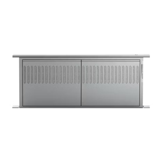
TELESCOPIC DOWNDRAFT VENT SYSTEM
HD30 and HD36 Vent models
HBD600I and HBD1200E Blower models
SYSTÈME DE VENTILATION TÉLESCOPIQUE
À ASPIRATION DESCENDANTE
Modèles de systèmes de ventilation HD30 et HD36
Modèles de ventilateurs HBD600I et HBD1200E
INSTALLATION GUIDE / USER GUIDE
GUIDE D'INSTALLATION / GUIDE D'UTILISATION
US CA
Advertisement
Chapters
Table of Contents

Related Manuals for Fisher & Paykel HBD600I


Summary of Contents for Fisher & Paykel HBD600I
- Page 1 TELESCOPIC DOWNDRAFT VENT SYSTEM HD30 and HD36 Vent models HBD600I and HBD1200E Blower models SYSTÈME DE VENTILATION TÉLESCOPIQUE À ASPIRATION DESCENDANTE Modèles de systèmes de ventilation HD30 et HD36 Modèles de ventilateurs HBD600I et HBD1200E INSTALLATION GUIDE / USER GUIDE GUIDE D’INSTALLATION / GUIDE D’UTILISATION US CA...
- Page 2 English Page 1 – 34 Français Page 37 – 70...
-
Page 3: Table Of Contents
CONTENTS Introduction Safety and warnings Venting requirements Electrical requirements Installation instructions Operating instructions Cleaning and maintenance Troubleshooting Parts and accessories Wiring diagram Limited Warranty IMPORTANT! Registration SAVE THESE INSTRUCTIONS Register your product with us so we can The models shown in this user guide may provide you with the best service possible. -
Page 5: Introduction
INTRODUCTION Thank you for purchasing a Fisher & Paykel product. This Installation and Use and Care Guide contains valuable information on how to properly install, operate and maintain your new Downdraft Vent System for years of safe and enjoyable service. To serve you better, please fill out and submit your Product Registration by visiting our website at www.fisherpaykel.com and selecting ‘Customer Care’... -
Page 7: Safety And Warnings
SAFETY AND WARNINGS – Sufficient air is needed for proper combustion and exhausting of gases through the flue (chimney) of fuel burning equipment to prevent back drafting. Follow the heating equipment manufacturer’s guideline and safety standards such as those published by the National Fire Protection Association (NFPA), and the American Society for Heating, Refrigeration and Air Conditioning Engineers (ASHRAE), and the local code authorities. - Page 10 INSTALLATION INSTRUCTIONS Downdraft unit contents of packaging TELESCOP C DOWNDRAFT VENT SYSTEM HD 0 and D36 V nt m de s HBD 00 and H D 200E l we mod ls SYSTÈME DE VENTILATION TÉLESCOP QUE À ASP RATION DESCENDANTE M dè...
- Page 11 INSTALLATION INSTRUCTIONS Internal blower (HBD600I) contents of packaging Internal blower box 6” (152 mm) diameter back draft damper Remote blower (HBD1200E) contents of packaging Remote blower Duct collar plate...
-
Page 14: Venting Requirements
To reduce risk of fire and to properly exhaust air, be sure to duct air outside – Do not vent exhaust air into spaces within walls or ceilings or into attics, crawl spaces, or garages. Compatible blowers with the downdraft vent system Internal blower model HBD600I. ● Remote blower model HBD1200E or Remote Blower Models max 2.8 A. - Page 15 INSTALLATION INSTRUCTIONS Plan the ductwork The internal blower can be mounted to the front or back of the downdraft unit and be ducted in multiple directions: left, right, down, forward or backwards. The remote blower can be ducted downwards from the front or back of the downdraft unit. In the event of installations where the blower is located on the back of the downdraft unit, it is advised to leave an access door or opening to reach the bottom of the downdraft unit, as well as where the wiring box and blower is located should service be needed.
- Page 16 INSTALLATION INSTRUCTIONS WARNING! This appliance is heavy and requires two persons for unpacking and installation. ● Installation work and electrical wiring must be done by qualified person(s) in ● accordance with all applicable codes and standards. IMPORTANT! Wear gloves to protect against sharp edges. ●...
- Page 17 INSTALLATION INSTRUCTIONS Prepare the downdraft unit for the intended blower Internal blower Remove the 10” (254 mm) blower connection plate from the front of the downdraft ● unit Fig.1. Attach the over counter mounting brackets in place with the two 3/ 1 6” (5 mm) screws ●...
- Page 18 INSTALLATION INSTRUCTIONS Temporarily insert the downdraft into the cabinet With the assistance of another person, lift the downdraft unit into the prepared cutout ● in the cabinet. The over counter mounting brackets should rest on the countertop. Secure the downdraft unit to the countertop with two 19/ 3 2” (15 mm) screws. ●...
- Page 19 INSTALLATION INSTRUCTIONS Internal blower installation in one of the following three options: Option 1: Internal blower, front installation for venting left, right or down Disconnect the cable from inside the downdraft unit. Plug in that same cable ● from the downdraft unit into the internal blower Fig.7. Turn the venting collar on the internal blower box to the desired direction –...
- Page 21 INSTALLATION INSTRUCTIONS Option 2: Sloped roof installation (For flat roof installations see Option 3) Choose location on the rear slope of the roof that minimizes vent run. ● Avoid obstacles such as TV leads, electric lines, etc. If the remote blower top is level with the roof peak, it will not be seen from the street.
- Page 22 INSTALLATION INSTRUCTIONS Prepare for electrical connection Downdraft unit Remove the cover of the terminal box from the downdraft unit Fig.14. ● Decide whether the power source should enter the downdraft unit from below or ● from the back and remove the respective knock out. Install a UL listed strain relief or conduit fitting (not included) in the knock out Fig.15.
-
Page 23: Electrical Requirements
INSTALLATION INSTRUCTIONS Electrical connection WARNING! Electrical wiring must be done by qualified person(s) in accordance with all applicable ● codes and standards and the unit must be grounded. This downdraft unit may only be used in connection with Fisher & Paykel internal or ●... - Page 24 INSTALLATION INSTRUCTIONS Downdraft unit internal blower electrical connection Connect (L1/live) wire from the power supply ● cable into the right terminal Fig.19. Connect the green (ground) wire from the power ● supply cable into the middle terminal Fig.19. Connect the (neutral) wire from the power supply ●...
-
Page 27: Operating Instructions
OPERATING INSTRUCTIONS The downdraft vent system is designed to remove smoke, cooking vapors and odors from the cooktop area. For best results, the downdraft vent system should be operating before cooking is started and should continue to operate for several minutes after cooking is complete. -
Page 28: Cleaning And Maintenance
CLEANING AND MAINTENANCE WARNING! Unplug or disconnect the appliance from the power supply before servicing or cleaning. IMPORTANT! Never use abrasive or oil based cleaners. ● Wear gloves to protect against sharp edges. ● Maintenance The downdraft vent system should be cleaned regularly using a mild, liquid detergent and a clean soft cloth to avoid a build-up of grease occurring. -
Page 29: Troubleshooting
TROUBLESHOOTING Spills IMPORTANT! If a spill occurs on the cooktop that allows liquids to seep inside the downdraft unit, you must turn the downdraft vent system off immediately. It is possible to cause damage to the downdraft unit if water is allowed inside the downdraft unit while it is operating. -
Page 31: Parts And Accessories
PARTS AND ACCESSORIES ITEM REFERENCE NUMBER Internal blower HBD600I Remote blower model HBD1200E Filter HD30 290317 Filter HD36 290334... -
Page 32: Wiring Diagram
WIRING DIAGRAM Downdraft unit wiring diagram... -
Page 34: Limited Warranty
LIMITED WARRANTY When you purchase any new Fisher & Paykel ventilation product for personal or consumer use you automatically receive a two year limited warranty covering parts and labor for servicing within the 48 mainland United States, Hawaii, Washington DC and Canada. - Page 35 LIMITED WARRANTY This limited warranty does not cover: Service calls that are not related to any defect in the product. The cost of a service call will be charged if the problem is not found to be a defect of the product. For example: Correcting faulty installation of the product.
- Page 36 LIMITED WARRANTY How to get service Please read your user guide. If you then have any questions about operating the product, need the name of your local Fisher & Paykel Authorized Service Agent, or believe the product is defective and wish service under this limited warranty, please contact your dealer or call us at: USA and Canada TOLL FREE 1.888.9.FNP.USA (1.888.936.7872)
-
Page 39: Important
TABLE DES MATIÈRES Introduction Consignes de sécurité et mises en garde Exigences relatives à l’évacuation Exigences électriques Instructions d’installation Instructions d’utilisation Nettoyage et entretien Dépannage Pièces et accessoires Schéma de câblage Garantie limitée IMPORTANT! Enregistrement CONSERVEZ CES INSTRUCTIONS Enregistrez votre produit afin que nous Les modèles illustrés dans ce guide d’utilisation puissions vous offrir un service de la peuvent ne pas être disponibles dans tous les... -
Page 41: Introduction
INTRODUCTION Nous vous remercions d’avoir acheté ce produit Fisher & Paykel. Ce Guide d’installation, d’utilisation et d’entretien contient des informations très utiles sur la façon adéquate d’installer, de faire fonctionner et d’effectuer l’entretien de votre nouveau système de ventilation à aspiration descendante, qui vous permettront d’en profiter en toute sécurité... -
Page 43: Consignes De Sécurité Et Mises En Garde
CONSIGNES DE SÉCURITÉ ET MISES EN GARDE – Pour éviter le refoulement d’air, une quantité d’air suffisante est nécessaire pour assurer une bonne combustion et l’évacuation des gaz à travers le carneau (cheminée) de l’appareil. Suivez les consignes du fabricant de l’appareil de cuisson ainsi que les normes de sécurité... - Page 46 INSTRUCTIONS D’INSTALLATION Unité d’aspiration descendante – Contenu de l’emballage TELESCOP C DOWNDRAFT VENT SYSTEM HD 0 and D36 V nt m de s HBD 00 and H D 200E l we mod ls SYSTÈME DE VENTILATION TÉLESCOP QUE À ASP RATION DESCENDANTE M dè...
- Page 47 INSTRUCTIONS D’INSTALLATION Ventilateur interne (HBD600I) – Contenu de l’emballage Boîtier de ventilateur Clapet anti-refoulement interne d’air de 6 po (152 mm) de diamètre Ventilateur à distance (HBD1200E) – Contenu de l’emballage Ventilateur à distance Plaque avec collet pour conduit...
-
Page 50: Exigences Relatives À L'évacuation
N’évacuez pas l’air dans les murs, plafonds, greniers, vides sanitaires ou garages. Ventilateurs compatibles avec le système de ventilation à aspiration descendante Modèle de ventilateur interne HBD600I. ● Modèle de ventilateur à distance HBD1200E ou modèles de ventilateur à distance d’un ●... - Page 51 INSTRUCTIONS D’INSTALLATION Planifiez le trajet de conduit Le ventilateur interne peut être installé à l’avant ou l’arrière de l’unité d’aspiration descendante, avec un conduit orienté dans l’une de ces directions : gauche, droite, bas, avant ou arrière. Le ventilateur à distance peut être raccordé à un conduit orienté vers le bas, à...
- Page 52 INSTRUCTIONS D’INSTALLATION MISE EN GARDE! Cet appareil est lourd. Il doit être déballé et installé par deux personnes. ● L’installation et le câblage électrique doivent être réalisés par une ou plusieurs ● personne(s) qualifiée(s), en conformité avec tous les codes et toutes les normes applicables.
- Page 53 INSTRUCTIONS D’INSTALLATION Préparez l’unité d’aspiration descendante pour le ventilateur utilisé Ventilateur interne Retirez la plaque de raccordement de 10 po (254 mm) pour ventilateur de la partie ● avant de l’unité d’aspiration descendante (Fig.1). Installez les pièces de fixation pour dessus de comptoir à l’aide des deux vis de 3/ 1 6 po ●...
- Page 54 INSTRUCTIONS D’INSTALLATION Insérez temporairement l’unité d’aspiration descendante dans l’armoire Avec l’aide d’une autre personne, soulevez l’unité d’aspiration descendante dans ● l’ouverture que vous avez préparée dans l’armoire. Les pièces de fixation pour dessus de comptoir doivent reposer sur le comptoir. Fixez l’unité...
- Page 55 INSTRUCTIONS D’INSTALLATION Installation du ventilateur interne à l’aide d’une des trois options suivantes : Option 1 : Ventilateur interne, installation par l’avant pour évacuation vers la gauche, la droite ou le bas Déconnectez le câble à l’intérieur de l’unité d’aspiration descendante. Branchez ● ce même câble de l’unité...
- Page 57 INSTRUCTIONS D’INSTALLATION Option 2 : Installation sur un toit incliné (Pour les installations sur un toit plat, voir l’Option 3) Choisissez l’emplacement sur la pente arrière du toit, en veillant à minimiser la ● longueur de conduit. Évitez les obstacles tels que les câbles de télévision, lignes électriques, etc.
- Page 58 INSTRUCTIONS D’INSTALLATION Préparation pour le raccordement électrique Unité d’aspiration descendante Retirez le couvercle de la boîte de jonction de l’unité d’aspiration descendante (Fig.14). ● Choisissez la position de raccordement de la source d’alimentation à l’unité ● d’aspiration descendante (à partir du dessous ou de l’arrière), puis retirez l’alvéole défonçable correspondante.
- Page 59 INSTRUCTIONS D’INSTALLATION Raccordement électrique MISE EN GARDE! Le câblage électrique doit être réalisé par une ou plusieurs personne(s) qualifiée(s), ● en conformité avec tous les codes et toutes les normes applicables, en veillant à ce que l’appareil soit mis à la terre. Cette unité...
- Page 60 INSTRUCTIONS D’INSTALLATION Raccordement électrique du ventilateur interne de l’unité d’aspiration descendante Connectez le (L1/sous tension) du câble ● d’alimentation électrique à la borne de droite (Fig.19). Connectez le fil vert (terre) du câble d’alimentation ● électrique à la borne du centre (Fig.19). Connectez le (neutre) du câble d’alimentation ●...
-
Page 63: Instructions D'utilisation
INSTRUCTIONS D’UTILISATION Le système de ventilation à aspiration descendante est conçu pour éliminer la fumée, les vapeurs de cuisson et les odeurs de la zone de votre surface de cuisson. Pour de meilleurs résultats, il est recommandé de démarrer le système de ventilation à aspiration descendante avant de commencer la cuisson, puis de le laisser fonctionner plusieurs minutes après avoir terminé. -
Page 64: Nettoyage Et Entretien
NETTOYAGE ET ENTRETIEN MISE EN GARDE! Débranchez ou déconnectez l’appareil de l’alimentation électrique avant de procéder à l’entretien ou au nettoyage. IMPORTANT! N’utilisez jamais de nettoyants abrasifs ou à base d’huile. ● Portez des gants pour vous protéger des rebords tranchants. ●... - Page 65 DÉPANNAGE Déversements IMPORTANT! En cas de déversement sur la surface de cuisson de liquides risquant de pénétrer à l’intérieur de l’unité d’aspiration descendante, éteignez immédiatement le système de ventilation à aspiration descendante. Des dommages peuvent être causés à l’unité d’aspiration descendante si de l’eau pénètre dans celle-ci pendant qu’elle fonctionne. Éteignez immédiatement le système de ventilation à...
-
Page 67: Pièces Et Accessoires
PIÈCES ET ACCESSOIRES ARTICLE NUMÉRO DE RÉFÉRENCE Ventilateur interne HBD600I Modèle de ventilateur à distance HBD1200E Filtre HD30 290317 Filtre HD36 290334... -
Page 68: Schéma De Câblage
SCHÉMA DE CÂBLAGE Schéma de câblage de l’unité d’aspiration descendante NOIR NOIR BRUN BLEU BLEU BLEU BRUN BRUN NOIR BRUN ROSE BLANC BRUN BLEU NOIR BLEU GRIS BRUN BLEU BRUN BLEU BRUN BRUN ORANGE ORANGE BLEU ORANGE ORANGE GRIS ROUGE BLEU NOIR NOIR... -
Page 70: Garantie Limitée
GARANTIE LIMITÉE Lorsque vous achetez un nouvel appareil de ventilation Fisher & Paykel destiné à un usage personnel ou celui d’un consommateur, vous bénéficiez automatiquement d’une garantie limitée de deux ans s’appliquant aux pièces et à la main-d’œuvre pour le service dans les 48 États continentaux des États-Unis, à Hawaï, à Washington DC et au Canada. - Page 71 GARANTIE LIMITÉE Cette garantie limitée ne couvre pas : Les demandes de réparation pour tout problème non lié à une défectuosité du produit. Le coût de la demande de réparation sera facturé s’il se trouve que le problème n’est pas dû à une défectuosité du produit. Par exemple : Correction d’une installation inappropriée du produit.
- Page 72 GARANTIE LIMITÉE Comment obtenir du service Veuillez lire votre guide d’utilisation. Si vous avez des questions concernant l’utilisation du produit, souhaitez trouver le nom d’un agent de service autorisé Fisher & Paykel local ou pensez que le produit est défectueux et désirez le faire réparer dans le cadre de cette garantie limitée, veuillez communiquer avec votre détaillant ou nous appeler au numéro suivant : États-Unis et Canada...
- Page 76 FISHERPAYKEL.COM © Fisher & Paykel Appliances 2018. All rights reserved. The product specifications in this booklet apply to the specific products and models described at the date of issue. Under our policy of continuous product improvement, these specifications may change at any time. You should therefore check with your Dealer to ensure this booklet correctly describes the product currently available.