Table of Contents
Advertisement
Quick Links
Advertisement
Table of Contents

Related Manuals for Delta Electronics ASDA-A Series


Summary of Contents for Delta Electronics ASDA-A Series
- Page 4 Contents of this manual This manual is a user guide that provides information on how to install, operate and maintain ASDA-A series AC servo drives and ASMT series AC servo motors. The contents of this manual are including the following topics:...
- Page 5 SAFETY PRECAUTIONS ASDA-A series drives are open type, variable frequency and insulated gate bipolar transistor AC monitor controller incorporating microprocessor technology. They are operated from a single or three-phase source of supply, and intended to control three-phase permanent magnet synchronous motors (PMSM) by means of a variable frequency, variable voltage output, used in industrial applications and for installation in an end-use enclosure.
- Page 6 Use multi-stranded twisted-pair wires or multi-core shielded-pair wires for signal, encoder (PG) feedback cables. The maximum length of command input cable is 3m and the maximum length of encoder (PG) feedback cables is 20m. 4th Edition 2005/11/30, HE03 © DELTA ELECTRONICS, INC. ALL RIGHTS RESERVED...
- Page 7 Connect the servo motor once it has successfully completed a trail run. Trial Run with Load CAUTION After the trial run without load is completed, conduct a second trial run with load. 4th Edition 2005/11/30, HE03 © DELTA ELECTRONICS, INC. ALL RIGHTS RESERVED...
-
Page 8: Table Of Contents
3-1-4 Mot or Po wer Cabl e Co nnecto r Specificati o ns ........3-4 3-1-5 Enc oder Co nn ector Spe c ifications ........... 3-6 3-1-6 Cab le Specifi cations fo r Servo Drive ..........3-7 4th Edition 2005/11/30, HE03 © DELTA ELECTRONICS, INC. ALL RIGHTS RESERVED... - Page 9 4-4-4 DO signal F orce Outp ut Dia gnosi s Opera ti on ........4-8 4-4-5 DI s i gnal Disp lay Di agn osis Operation ..........4-9 4-4-6 DO signal Dis pla y Diag nosis Ope ration ..........4-10 4th Edition 2005/11/30, HE03 © DELTA ELECTRONICS, INC. ALL RIGHTS RESERVED...
- Page 10 6-3-2 Stru cture of Speed Co nt rol Mo de ............. 6-15 6-3-3 Smo othing Strateg y of Speed Co nt rol Mo de ........6-16 6-3-4 Anal og In put Propo rtion a l Gain (Sc alar) ........... 6-19 4th Edition 2005/11/30, HE03 © DELTA ELECTRONICS, INC. ALL RIGHTS RESERVED...
- Page 11 8 - 3 M O D B U S C o m m u n i c a t i o n Pro tocol ............8-7 8-4 Co mmunicatio n Para mete r Write -in and Rea d-out ........8-14 viii 4th Edition 2005/11/30, HE03 © DELTA ELECTRONICS, INC. ALL RIGHTS RESERVED...
- Page 12 12-6 Feed Step Control ................12-14 12-7 Internal Auto Running Mode ..............12-25 12-8 Homing Function ................. 12-30 12-9 External Controller Connection Examples..........12-37 Appendix A: Accessories ............. A-1 4th Edition 2005/11/30, HE03 © DELTA ELECTRONICS, INC. ALL RIGHTS RESERVED...
- Page 13 FA X : 1 - 9 1 9 - 7 6 7 - 3 9 6 9 FA X : 3 1 - 4 0 - 2 5 9 - 2 8 5 1 4th Edition 2005/11/30, HE03 © DELTA ELECTRONICS, INC. ALL RIGHTS RESERVED...
-
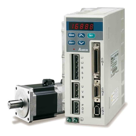
Page 14: Chapter 1 Unpacking Check And Model Explanation
One encoder cable, which is used to connect the encoder of servo motor and CN2 terminal of servo drive. CN1 Connector: 50 PIN Connector (3M type analog product) CN2 Connector: 20 PIN Connector (3M type analog product) 4th Edition 2005/11/30, HE03 © DELTA ELECTRONICS, INC. ALL RIGHTS RESERVED... -
Page 15: Model Explanation
Chapter 1 Unpacking Check and Model Explanation ASDA-A User Manual CN3 Connector: 6 PIN Connector (IEEE1394 analog product) Model Explanation 1-2-1 Nameplate ASDA-A Series Servo Drive Nameplate Explanation Serial Number Explanation 4th Edition 2005/11/30, HE03 © DELTA ELECTRONICS, INC. ALL RIGHTS RESERVED... -
Page 16: Model Name
ASDA-A User Manual Chapter 1 Unpacking Check and Model Explanation ASMT Series Servo Motor Nameplate Explanation Serial Number Explanation 1-2-2 Model Name ASDA-A Series Servo Drive 4th Edition 2005/11/30, HE03 © DELTA ELECTRONICS, INC. ALL RIGHTS RESERVED... - Page 17 Chapter 1 Unpacking Check and Model Explanation ASDA-A User Manual ASMT Series Servo Motor 4th Edition 2005/11/30, HE03 © DELTA ELECTRONICS, INC. ALL RIGHTS RESERVED...
-
Page 18: Servo Drive And Servo Motor Combinations
Servo Drive and Servo Motor Combinations The tables below show the possible combination of Delta ASDA-A series servo drives and ASMT series servo motors. The boxes ( ) at the end of the model names are for version or optional configurations. - Page 19 The drives shown in the above table are designed according to the three multiple of rated current of motors shown in the above table. If the drives which are designed according to the six multiple of rated current of motors are needed, please contact our distributors. 4th Edition 2005/11/30, HE03 © DELTA ELECTRONICS, INC. ALL RIGHTS RESERVED...
-
Page 20: Servo Drive Features
ASDA-A User Manual Chapter 1 Unpacking Check and Model Explanation Servo Drive Features 4th Edition 2005/11/30, HE03 © DELTA ELECTRONICS, INC. ALL RIGHTS RESERVED... -
Page 21: Control Modes Of Servo Drive
The new control mode will only be valid after drive off/on action. Please see CAUTION on page iv (switching drive off/on multiple times). 4th Edition 2005/11/30, HE03 © DELTA ELECTRONICS, INC. ALL RIGHTS RESERVED... -
Page 22: Molded-Case Circuit Breaker, Fuse And Leakage Current
60A (peak) 0.08mA 0.2mA ASD-A1521LA 66A (peak) 0.09mA 0.21mA ASD-A1521MA 66A (peak) 0.09mA 0.21mA ASD-A2023LA 73A (peak) 0.12mA ASD-A2023MA 73A (peak) 0.12mA ASD-A3023LA 107A (peak) 0.13mA ASD-A3023MA 107A (peak) 0.13mA 4th Edition 2005/11/30, HE03 © DELTA ELECTRONICS, INC. ALL RIGHTS RESERVED... - Page 23 Chapter 1 Unpacking Check and Model Explanation ASDA-A User Manual This page intentionally left blank. 1-10 4th Edition 2005/11/30, HE03 © DELTA ELECTRONICS, INC. ALL RIGHTS RESERVED...
-
Page 24: Chapter 2 Installation And Storage
Caution The servo drive and motor will generate heat. If they are installed in a control panel, please ensure sufficient space around the units for heat dissipation. 4th Edition 2005/11/30, HE03 © DELTA ELECTRONICS, INC. ALL RIGHTS RESERVED... -
Page 25: Installation Procedure And Minimum Clearances
Do not install the drive in a horizontal position or malfunction and damage will occur. 4th Edition 2005/11/30, HE03 © DELTA ELECTRONICS, INC. ALL RIGHTS RESERVED... - Page 26 Install a fan to increase ventilation to avoid ambient temperatures that exceed the specification. When installing two or more drive adjacent to each other please follow the clearances as shown in the following diagram. Minimum Clearances 4th Edition 2005/11/30, HE03 © DELTA ELECTRONICS, INC. ALL RIGHTS RESERVED...
- Page 27 Chapter 2 Installation and Storage ASDA-A User Manual Side by Side Installation 4th Edition 2005/11/30, HE03 © DELTA ELECTRONICS, INC. ALL RIGHTS RESERVED...
-
Page 28: Chapter 3 Configuration And Wiring
ASDA-A User Manual Chapter 3 Configuration and Wiring Chapter 3 Configuration and Wiring This chapter provides information on wiring ASDA-A series products, the descriptions of I/O signals and gives typical examples of wiring diagrams. Configuration 3-1-1 Connecting to Peripheral Devices In Figure 3.1, it briefly explains how to connect each peripheral device. -
Page 29: Servo Drive Connectors And Terminals
Yellow/Black Black Communication connector Used to connect PC or controller. Refer to section 3-5 for details. Note: U, V ,W , CN1, CN2, CN3 terminals provide short circuit protection. 4th Edition 2005/11/30, HE03 © DELTA ELECTRONICS, INC. ALL RIGHTS RESERVED... -
Page 30: Wiring Methods
1MC/a : self-holding power 1MC : contact of main circuit power. Figure 3.2 Three-Phase Power Supply Connection R S T 1MCCB Alarm Power Power Processing Noise filter 1MC/x 1MC/a Servo Drive 4th Edition 2005/11/30, HE03 © DELTA ELECTRONICS, INC. ALL RIGHTS RESERVED... -
Page 31: Motor Power Cable Connector Specifications
Motor Part Number Terminal U, V, W / Electromagnetic Brake Connector Power Rating Description Identification 100W ASMT01L250A 200W ASMT02L250A 400W ASMT04L250A 750W ASMT07L250A 100W ASMT01L250B 200W ASMT02L250B 400W ASMT04L250B 750W ASMT07L250B 4th Edition 2005/11/30, HE03 © DELTA ELECTRONICS, INC. ALL RIGHTS RESERVED... - Page 32 U, V, W / Electromagnetic Brake Connector Power Rating Description Identification ASMT10L250 ASMT10M250 1.5kW ASMT15M250 ASMT20L250 ASMT30L250 20-18 ASMT20M250 ASMT30M250 24-11 Terminal CASE GROUND BRAKE1 BRAKE2 Identification (Black) (White) (Red) (Green) (Orange) (Yellow) 4th Edition 2005/11/30, HE03 © DELTA ELECTRONICS, INC. ALL RIGHTS RESERVED...
-
Page 33: Encoder Connector Specifications
ASMT01L250 200W ASMT02L250 400W ASMT04L250 750W ASMT07L250 ASMT10L250 ASMT10M250 1.5kW ASMT15M250 ASMT20L250 ASMT20M250 ASMT30L250 20-29 ASMT30M250 17-#16 Terminal BRAID Identification (Blue) (Blue/Black) (Green) (Green/Black) (Yellow) (Yellow/Black) (Red) (Black) SHELD 4th Edition 2005/11/30, HE03 © DELTA ELECTRONICS, INC. ALL RIGHTS RESERVED... -
Page 34: Cable Specifications For Servo Drive
2. If the encoder cable is too short, please use a twisted-shield signal wire with grounding conductor. The wire length should be 20m or less. For lengths greater than 20m, the wire gauge should be doubled in order to lessen any signal attenuation. 4th Edition 2005/11/30, HE03 © DELTA ELECTRONICS, INC. ALL RIGHTS RESERVED... - Page 35 30m. If the wiring distance is longer than 30m, please choose the adequate wire size according to the voltage. 4. The shield of shielded twisted-pair cables should be connected to the SHIELD end (terminal marked ) of the servo drive. 4th Edition 2005/11/30, HE03 © DELTA ELECTRONICS, INC. ALL RIGHTS RESERVED...
-
Page 36: Basic Wiring
DRIVER circuit +24V External speed Current control External torque Position pulse Digital input Digital output Analog monitor output Encoder signal A, B, Z output Display Serial communication RS-232/RS-485 /RS-422 4th Edition 2005/11/30, HE03 © DELTA ELECTRONICS, INC. ALL RIGHTS RESERVED... - Page 37 DRIVER +24V External speed Current control External torque Position pulse Digital input Digital output Analog monitor output Encoder signal A, B, Z output Display Serial communication RS-232/RS-485 /RS-422 3-10 4th Edition 2005/11/30, HE03 © DELTA ELECTRONICS, INC. ALL RIGHTS RESERVED...
-
Page 38: Input / Output Interface Connector -Cn1
A detailed explanation of each group is available in section 3-3-2, tables 3-B, 3-C & 3-D. 3-3-1 CN1 Terminal Identification Figure 3.6 shows the layout of CN1 connector: Figure 3.6 3-11 4th Edition 2005/11/30, HE03 © DELTA ELECTRONICS, INC. ALL RIGHTS RESERVED... - Page 39 Note: The terminals marked "NC" must be left unconnected (No Connection). The NC terminals are used within the servo drive. Any outside connection to the NC terminals will result in damage to the drive and void the warranty! 3-12 4th Edition 2005/11/30, HE03 © DELTA ELECTRONICS, INC. ALL RIGHTS RESERVED...
-
Page 40: Signals Explanation Of Connector Cn1
17. The motor encoder signals are available through these C11/C12 terminals. The encoder output pulse count can be set Position via parameter P1-46. Pulse Output 3-13 4th Edition 2005/11/30, HE03 © DELTA ELECTRONICS, INC. ALL RIGHTS RESERVED... - Page 41 For Example; The alarm setting DO 5 (pins 28/27) can be assigned to DO 1 (pins 7/6) and vise versa. 3-14 4th Edition 2005/11/30, HE03 © DELTA ELECTRONICS, INC. ALL RIGHTS RESERVED...
- Page 42 Target Rotation Speed setting as defined in parameter P1-39. TSPD will remain activated until the motor speed drops below the Target Rotation Speed. 3-15 4th Edition 2005/11/30, HE03 © DELTA ELECTRONICS, INC. ALL RIGHTS RESERVED...
- Page 43 1. PINS 3 & 2 can either be TSPD or HOME dependent upon control mode selected. 2. PINS 1 & 26 are different depending on control mode either BRKR or TPOS. 3-16 4th Edition 2005/11/30, HE03 © DELTA ELECTRONICS, INC. ALL RIGHTS RESERVED...
- Page 44 TCM0 Pt, T, Tz, Pt-T Select the source of torque command: Pr-T, S-T See table 3.G. TCM1 Pt-S, Pr-S Speed / Position mode switching OFF: Speed, ON: Position 3-17 4th Edition 2005/11/30, HE03 © DELTA ELECTRONICS, INC. ALL RIGHTS RESERVED...
- Page 45 Step up input. When STEPU is activated, the motor will run to next position. STEPD Not assigned Step down input. When STEPD is activated, the motor will run to previous position. 3-18 4th Edition 2005/11/30, HE03 © DELTA ELECTRONICS, INC. ALL RIGHTS RESERVED...
- Page 46 3.D above, as each control mode is separated and listed in different row, it is easy for user to view and can avoid confusion. However, the Pin number of each signal can not be displayed in the table 3.H and table 3.I. 3-19 4th Edition 2005/11/30, HE03 © DELTA ELECTRONICS, INC. ALL RIGHTS RESERVED...
- Page 47 (contact b) Reverse inhibit limit DI6 DI6 DI6 DI6 DI6 DI6 (contact b) Forward inhibit limit CCWL DI7 DI7 DI7 DI7 DI7 DI7 (contact b) Reference “Home” ORGP sensor 3-20 4th Edition 2005/11/30, HE03 © DELTA ELECTRONICS, INC. ALL RIGHTS RESERVED...
- Page 48 (Numerator) selection 0 [see P2-60~P2-62] Electronic gear ratio GNUM1 (Numerator) selection 1 [see P2-60~P2-62] INHP Pulse inhibit input Note: For Pin numbers of DI1~DI8 signals, please refer to section 3-3-1. 3-21 4th Edition 2005/11/30, HE03 © DELTA ELECTRONICS, INC. ALL RIGHTS RESERVED...
-
Page 49: User-Defined Di And Do Signals
P2-18 DI2- P2-11 DO1- DI3- P2-12 DO2+ P2-19 DI4- P2-13 DO2- DI5- P2-14 DO3+ P2-20 DI6- P2-15 DO3- DI7- P2-16 DO4+ P2-21 DI8- P2-17 DO4- DO5+ P2-22 DO5- 3-22 4th Edition 2005/11/30, HE03 © DELTA ELECTRONICS, INC. ALL RIGHTS RESERVED... - Page 50 INDEX1 Feed step selection input 1 (bit 1) INDEX2 Feed step selection input 2 (bit 2) INDEX3 Feed step selection input 3 (bit 3) INDEX4 Feed step selection input 4 (bit 4) 3-23 4th Edition 2005/11/30, HE03 © DELTA ELECTRONICS, INC. ALL RIGHTS RESERVED...
- Page 51 For example: If users want to set DO1 to be servo ready, it only needs to set the value of parameter P2-18 to 101 (refer to chapter 7). Note: 0: Output function disabled 3-24 4th Edition 2005/11/30, HE03 © DELTA ELECTRONICS, INC. ALL RIGHTS RESERVED...
-
Page 52: Wiring Diagrams Of I/O Signals (Cn1)
(PULSE) SIGN (PULSE) (41) COM- Be sure to connect a diode when the drive is applied to inductive load. (Continuous maximum current: 40mA, Instantaneous peak current: max. 100mA) 3-25 4th Edition 2005/11/30, HE03 © DELTA ELECTRONICS, INC. ALL RIGHTS RESERVED... - Page 53 DO5: (28, 27) DO5: (28, 27) DC24V DC24V 50mA DOX- DOX- Ensure the polarity (+, -) of the Diode is correct or it may damage the drive. X=1,2,3,4,5 3-26 4th Edition 2005/11/30, HE03 © DELTA ELECTRONICS, INC. ALL RIGHTS RESERVED...
- Page 54 OA or OB or OZ OA or OB or OZ current: 40mA current: 40mA High speed /OA or /OB or /OZ photocoupler /OA or /OB or /OZ AM26CS32 type 3-27 4th Edition 2005/11/30, HE03 © DELTA ELECTRONICS, INC. ALL RIGHTS RESERVED...
-
Page 55: Encoder Connector Cn2
Encoder B phase output /B phase input Encoder /B phase output Z phase input Encoder Z phase output 14,16 Encoder power Encoder 5V power 13,15 Encoder power Grounding 3-28 4th Edition 2005/11/30, HE03 © DELTA ELECTRONICS, INC. ALL RIGHTS RESERVED... -
Page 56: Serial Communication Connector Cn3
RS-422 data For data transmission of the servo drive RS-422-TX- transmission (differential line driver - end) Note: For the connection of RS-485, please refer to page 8-2 and 8-3. 3-29 4th Edition 2005/11/30, HE03 © DELTA ELECTRONICS, INC. ALL RIGHTS RESERVED... -
Page 57: Connection Between Pc And Connector Cn3
Chapter 3 Configuration and Wiring ASDA-A User Manual 3-5-2 Connection between PC and Connector CN3 3-30 4th Edition 2005/11/30, HE03 © DELTA ELECTRONICS, INC. ALL RIGHTS RESERVED... -
Page 58: Standard Connection Example
DO 5- RS23 2_TX RS23 2_GND *1: Please refer to the C4 wiring diagram on page 3-25. If it is open-collector input, please refer to C3 wiring diagram. 3-31 4th Edition 2005/11/30, HE03 © DELTA ELECTRONICS, INC. ALL RIGHTS RESERVED... -
Page 59: Position (Pr) Control Mode
RS42 2T- T POS DO 4- RS42 2T+ 1 .5K RS42 2R- & RS2 32_R X DO 5+ ALRM RS42 2R+ DO 5- RS23 2_TX RS23 2_GN D 3-32 4th Edition 2005/11/30, HE03 © DELTA ELECTRONICS, INC. ALL RIGHTS RESERVED... -
Page 60: Speed Control Mode
DO 4+ CN 3 RS4 22T- BRKR DO 4- RS4 22T+ 1.5K DO 5+ RS4 22R- & RS232_RX ALR M RS4 22R+ DO 5- RS2 32_TX RS2 32_GND 3-33 4th Edition 2005/11/30, HE03 © DELTA ELECTRONICS, INC. ALL RIGHTS RESERVED... -
Page 61: Torque Control Mode
DO3- 1.5K R S422 T+ DO4+ BRKR R S422 R- & R S232 _RX DO4- 1.5K R S422 R+ DO5+ ALRM R S232 _TX DO5- R S232 _GND 3-34 4th Edition 2005/11/30, HE03 © DELTA ELECTRONICS, INC. ALL RIGHTS RESERVED... -
Page 62: Chapter 4 Display And Operation
Pressing the DOWN arrow key can scroll through the parameter groups, the various parameter settings in each group and change parameter settings. SET Key Pressing the SET key can select, display and save the parameter groups, the various parameter settings. 4th Edition 2005/11/30, HE03 © DELTA ELECTRONICS, INC. ALL RIGHTS RESERVED... -
Page 63: Display Flowchart
(6) After the setting value change is completed, press Set key to save parameter setting or execute command. (7) When the parameter setting is completed, LCD display will show the end code “-END-“ and automatically return back to monitor mode. 4th Edition 2005/11/30, HE03 © DELTA ELECTRONICS, INC. ALL RIGHTS RESERVED... -
Page 64: Status Display
When entering into setting mode, pressing UP or DOWN arrow key can increase/decrease the display value. SHIFT key is used to change the selected digit (The selected digit will blink). 4th Edition 2005/11/30, HE03 © DELTA ELECTRONICS, INC. ALL RIGHTS RESERVED... -
Page 65: Monitor Setting Display
Input frequency of pulse command [kHz] Motor rotation speed [rpm] Speed input command 1 Speed input command 2 [rpm] Torque input command 1 Torque input command 2 4th Edition 2005/11/30, HE03 © DELTA ELECTRONICS, INC. ALL RIGHTS RESERVED... - Page 66 Negative value display (The decimal place is lower than five) Display value: -1234. Negative value display (The decimal place is greater than four) Display value: -12345. Decimal point display Display value: 12.34. 4th Edition 2005/11/30, HE03 © DELTA ELECTRONICS, INC. ALL RIGHTS RESERVED...
-
Page 67: General Function Operation
To change JOG speed again, press the MODE key. The servo Drive will display "P4 - 05". Press the SET key and the JOG rpm speed will displayed again. Refer back to #2 and #3 to change speed. 4th Edition 2005/11/30, HE03 © DELTA ELECTRONICS, INC. ALL RIGHTS RESERVED... -
Page 68: Position Learning Operation
In the position learning mode (display JOGox), pressing Shift key can directly change the “x” value of the display “JOGox” so as to jump rapidly to the particular learning position where should be modified. There is no position memorized at this time. 4th Edition 2005/11/30, HE03 © DELTA ELECTRONICS, INC. ALL RIGHTS RESERVED... -
Page 69: Do Signal Force Output Diagnosis Operation
DO signal force output diagnosis operation (OP x) mode. Pressing UP or DOWN arrow key can change “x” value from 1 to 5 and force digital output signals DO1 to DO5 to be ON or OFF. (Please also refer to Figure 4.6). 4th Edition 2005/11/30, HE03 © DELTA ELECTRONICS, INC. ALL RIGHTS RESERVED... -
Page 70: Di Signal Display Diagnosis Operation
LED display. When the segment lit and display on the screen, it means that the digital input signal is ON. (Please also refer to Figure 4.7). Figure 4.7 DI10 DI9 DI8 DI7 DI6 DI5 DI4 DI3 DI2 DI1 Light: 4th Edition 2005/11/30, HE03 © DELTA ELECTRONICS, INC. ALL RIGHTS RESERVED... -
Page 71: Do Signal Display Diagnosis Operation
LED display. When the segment lit and display on the screen, it means that the digital input signal is ON. (Please also refer to Figure 4.8) Figure 4.8 DO10 DO9 DO8 DO5DO4 DO3 DO2 DO1 Light: OFF OFF OFF 4-10 4th Edition 2005/11/30, HE03 © DELTA ELECTRONICS, INC. ALL RIGHTS RESERVED... -
Page 72: Chapter 5 Trial Run And Tuning Procedure
3. Ensure that all user defined parameters are set correctly. 4th Edition 2005/11/30, HE03 © DELTA ELECTRONICS, INC. ALL RIGHTS RESERVED... - Page 73 5. Ensure correct operation when using a relay and request assistance should there (Control power is be any unusual noises. 6. Check for abnormal conditions of the power indicators and LED display. applied) 4th Edition 2005/11/30, HE03 © DELTA ELECTRONICS, INC. ALL RIGHTS RESERVED...
-
Page 74: Applying Power To The Drive
If there is no text or character displayed on the LED display, please check if the voltage of the control circuit terminal (L1and L2) is over low. 1) When display shows: 4th Edition 2005/11/30, HE03 © DELTA ELECTRONICS, INC. ALL RIGHTS RESERVED... - Page 75 If it is necessary to use “Emergency Stop (EMGS)” as input signal, it only needs to confirm that which of digital inputs DI1~DI8 is set to “Emergency Stop (EMGS)” and check if the digital input signal is ON (It should be ON). 4th Edition 2005/11/30, HE03 © DELTA ELECTRONICS, INC. ALL RIGHTS RESERVED...
- Page 76 If the “ ” show on the display and “digital input 1” is set to Servo On (SON), it indicates that Servo on (SON) function is enabled. 6) When display shows: 4th Edition 2005/11/30, HE03 © DELTA ELECTRONICS, INC. ALL RIGHTS RESERVED...
- Page 77 Note: If there are any unknown fault codes and abnormal display when applying power to the drive or servo on is activated (without giving any command), please inform the distributor for assistance. 4th Edition 2005/11/30, HE03 © DELTA ELECTRONICS, INC. ALL RIGHTS RESERVED...
-
Page 78: Jog Trial Run Without Load
U, V, W terminals and enco der is corre ct or not. If the servo motor does not rotate p roperly, please check if the phase of U, V, W cables is connected correctly. 4th Edition 2005/11/30, HE03 © DELTA ELECTRONICS, INC. ALL RIGHTS RESERVED... -
Page 79: Speed Trial Run Without Load
(DI8) are disabled, i.e. the setting value of parameters P2-15 to P2-17 is set to 0 (Disabled). All the digital inputs of Delta ASDA-A series are user-defined, and the user can set the DI signals freely. Ensure to refer to the definitions of DI signals before defining them. - Page 80 -3000rpm at this time. Repeat the action of (3), (4), (5). When the motor is stopping, set DI to be OFF (Servo OFF). 4th Edition 2005/11/30, HE03 © DELTA ELECTRONICS, INC. ALL RIGHTS RESERVED...
-
Page 81: Position Trial Run Without Load
(DI8) are disabled, i.e. the setting value of parameters P2-15 to P2-17 is set to 0 (Disabled). All the digital inputs of Delta ASDA-A series are user-defined, and the user can set the DI signals freely. Ensure to refer to the definitions of DI signals before defining them. - Page 82 The command of internal position 3: P1-19 Rotation No. + P1-20 Pulse No. Set P1-21 to 100 (rotation number) Set P1-22 to 0 (pulse number) The command of internal position 4: P1-21 Rotation No. + P1-22 Pulse No. 5-11 4th Edition 2005/11/30, HE03 © DELTA ELECTRONICS, INC. ALL RIGHTS RESERVED...
- Page 83 -3000rpm at this time. Repeat the action of (3), (4), (5). When the motor is stopping, set DI to be OFF (Servo OFF). 5-12 4th Edition 2005/11/30, HE03 © DELTA ELECTRONICS, INC. ALL RIGHTS RESERVED...
-
Page 84: Tuning Procedure
MODE key once and press SET key twice to view the display on the keypad. Check if the value of J_load /J_motor is adjusted to a fixed value and displayed on the keypad after acceleration and deceleration repeatedly. 5-13 4th Edition 2005/11/30, HE03 © DELTA ELECTRONICS, INC. ALL RIGHTS RESERVED... -
Page 85: Tuning Flowchart
(2) Can use P2-23 and P2-24 to suppress the resonance of mechanical system. Use the selected tuning mode to adjust the gain and improve the drive performance. 5-14 4th Edition 2005/11/30, HE03 © DELTA ELECTRONICS, INC. ALL RIGHTS RESERVED... -
Page 86: Load Inertia Estimation Flowchart
(J_load / J_motor ) will show on the dis play. If the user desire to per form J OG ope ration a gain, pleas e pr ess MODE key - -> SET key - -> SET key. 5-15 4th Edition 2005/11/30, HE03 © DELTA ELECTRONICS, INC. ALL RIGHTS RESERVED... -
Page 87: Easy Mode Tuning Flowchart
Ple ase refe r to Tab le 5.A t o s et P2-0 0 and P 2-25. 5-16 4th Edition 2005/11/30, HE03 © DELTA ELECTRONICS, INC. ALL RIGHTS RESERVED... - Page 88 P2-25 must be 40Hz inputted manually 60Hz 115Hz 127Hz 103Hz The setting of P2-00 8~15 76Hz and P2-25 must be 15~25 62Hz inputted manually 25~50 45Hz 50~100 36Hz 5-17 4th Edition 2005/11/30, HE03 © DELTA ELECTRONICS, INC. ALL RIGHTS RESERVED...
-
Page 89: Automode (Pi) Tuning Flowchart
B to adjust P2-25 (Please refer to Table 5.B.) If the change of (J_load / J_motor) is not great, Servo off, and then set P2-32 to 3. Tuning is Complete 5-18 4th Edition 2005/11/30, HE03 © DELTA ELECTRONICS, INC. ALL RIGHTS RESERVED... - Page 90 Table 5.B P2-31 Value “B” Setting in AutoMode (PI) and the setting of P2-00, P2-25 P2-31 value “B” Speed Loop Responsive Recommended Setting Value of P2-25 20Hz 30Hz 40Hz 60Hz 85Hz 120Hz 160Hz 200Hz 250Hz 9 and above 300Hz 5-19 4th Edition 2005/11/30, HE03 © DELTA ELECTRONICS, INC. ALL RIGHTS RESERVED...
-
Page 91: Automode (Pdff) Tuning Flowchart
B to increase the responsiveness. If the change of (J_load / J_motor) is not great, Servo off, and then set P2-32 to 5. Tuning is Complete 5-20 4th Edition 2005/11/30, HE03 © DELTA ELECTRONICS, INC. ALL RIGHTS RESERVED... - Page 92 Speed Loop Responsiveness P2-31 value “B” Speed Loop Responsiveness 20HZ 120Hz 30 HZ 140HZ 40 HZ 160HZ 50 HZ 180HZ 60 HZ 200Hz 70 Hz 220Hz 80Hz 260Hz 100Hz 300HZ 5-21 4th Edition 2005/11/30, HE03 © DELTA ELECTRONICS, INC. ALL RIGHTS RESERVED...
-
Page 93: Manual Mode Tuning Flowchart
3. Th e settin g value of P2- 06 shou ld be equal to th e settin g value of P2- 00. Tuning is Complete 5-22 4th Edition 2005/11/30, HE03 © DELTA ELECTRONICS, INC. ALL RIGHTS RESERVED... -
Page 94: Limit Of Load Inertia Estimation
But, the measured inertia value will be memorized in P1-37 automatically when: Switching AutoMode #2 to AutoMode #3 Switching AutoMode #4 to AutoMode #5 5-23 4th Edition 2005/11/30, HE03 © DELTA ELECTRONICS, INC. ALL RIGHTS RESERVED... -
Page 95: Relationship Between Tuning Modes And Parameters
P1-37 (Ratio of Load Inertia to Servo AutoMode (PDFF) [Fixed P2-04, Motor Inertia [J_load / J_motor]) Inertia] (The inertia ratio P2-06, P2-31 Value B (Level of Fixed is determined by P1-37) P2-25, Responsiveness) P2-26, 5-24 4th Edition 2005/11/30, HE03 © DELTA ELECTRONICS, INC. ALL RIGHTS RESERVED... -
Page 96: Gain Adjustment In Manual Mode
However, if the setting value is over high, it may easily result in the vibration of machinery system. The recommended setting value is as follows: KVI (Parameter P2-06) 1.5 x Speed Loop Responsiveness 5-25 4th Edition 2005/11/30, HE03 © DELTA ELECTRONICS, INC. ALL RIGHTS RESERVED... - Page 97 If the value of electronic gear ratio (1-44 /1-45) is over than 10, the machinery system may also easily generate vibration or noise. 5-26 4th Edition 2005/11/30, HE03 © DELTA ELECTRONICS, INC. ALL RIGHTS RESERVED...
-
Page 98: Chapter 6 Control Modes Of Operation
Pr-T Either Pr or T control mode can be selected via the Digital Inputs (DI) Either S or T control mode can be selected via the Digital Inputs (DI) 4th Edition 2005/11/30, HE03 © DELTA ELECTRONICS, INC. ALL RIGHTS RESERVED... - Page 99 After the setting is completed, cut the power off and restart the drive again. The following sections describe the operation of each control mode, including control structure, command source and loop gain adjustment, etc. 4th Edition 2005/11/30, HE03 © DELTA ELECTRONICS, INC. ALL RIGHTS RESERVED...
-
Page 100: Position Control Mode
Position control mode includes Position (Pt) control mode and Position (Pr) control mode. The command source of Pt mode is external pulse train and the command source of Pr mode is internal parameters (P1-15 to P1-30). 4th Edition 2005/11/30, HE03 © DELTA ELECTRONICS, INC. ALL RIGHTS RESERVED... -
Page 101: Command Source Of Position (Pt) Control Mode
Position pulse can be input from these terminals, PULSE (41), /PULSE (43) and SIGN (37), /SIGN (36). It can be an open-collector circuit or line driver circuit. For the detail wiring, please refer to 3-6-1. 4th Edition 2005/11/30, HE03 © DELTA ELECTRONICS, INC. ALL RIGHTS RESERVED... -
Page 102: Command Source Of Position (Pr) Control Mode
P1 first and then give the position command P2. The difference between absolute and incremental position control is shown as the figure below: Absolute Type Incremental Type 20 turns 20 turns 10 turns 10 turns 4th Edition 2005/11/30, HE03 © DELTA ELECTRONICS, INC. ALL RIGHTS RESERVED... -
Page 103: Structure Of Position Control Mode
Using parameter can select Pr mode and Pt mode. Electronic gear ratio can be set in both two modes to set proper position revolution. ASDA-A series servo drive also provides P-curve and low-pass filter, which are used whenever the motor and load need to be operated more smoothly. As for the information of electronic gear ratio, P-curve and low-pass filter, please refer to the following sections. -
Page 104: P-Curve Filter For Position Control
P-curve filter. Position Time (ms) Speed Rated speed Time (ms) Torque Time (ms) TSL/2 TACC TSL/2 TSL/2 TACC TSL/2 P-curve characteristics and Time relationship (Acceleration) 4th Edition 2005/11/30, HE03 © DELTA ELECTRONICS, INC. ALL RIGHTS RESERVED... - Page 105 Unit: msec Note: If the setting value of parameter P1-36 is set to 0, it indicates Accel / Decel S-curve function is disabled and the command is just By-Pass. 4th Edition 2005/11/30, HE03 © DELTA ELECTRONICS, INC. ALL RIGHTS RESERVED...
-
Page 106: Electronic Gear Ratio
Encoder PPR: 2500 pulse Travel distance per load shaft revolution 3x1000 3000 When electronic gear function is Not Used 4x2500 10000 10000 When electronic gear =1 m function is Used 3000 4th Edition 2005/11/30, HE03 © DELTA ELECTRONICS, INC. ALL RIGHTS RESERVED... -
Page 107: Low-Pass Filter
Please refer to 6-2-2 to see the relationship between DI signals and parameters. The following figure is shown the timing chart of Pr mode: Internal position command POS0 POS1 External I/O signal POS2 CTRG >2ms, can be set by P2-09 6-10 4th Edition 2005/11/30, HE03 © DELTA ELECTRONICS, INC. ALL RIGHTS RESERVED... -
Page 108: Position Loop Gain Adjustment
Communication Addr.: 0202H Default: 5000 Applicable Control Mode: P Range: 10~20000 Unit: 0.0001 Position Control Block Diagram Feed forward Gain differentiator P2-02 Proportional Gain P2-00 Position Encoder Counter 6-11 4th Edition 2005/11/30, HE03 © DELTA ELECTRONICS, INC. ALL RIGHTS RESERVED... - Page 109 KPP value cannot meet the requirement of reasonable position track error demand. Adjust feed forward gain (Using parameter P2-02 can efficiently decrease the dynamic position track error). Position Position Time Time 6-12 4th Edition 2005/11/30, HE03 © DELTA ELECTRONICS, INC. ALL RIGHTS RESERVED...
-
Page 110: Speed Control Mode
Beside, in order to make the servo motor and load can be operate more smoothly, Delta servo drive also provide complete S-curve profile for speed control mode. In speed close loop, ASDA-A series servo drive provides gain adjustment and accumulation integrated PI controller. Also, ASDA-A series servo drive provides three modes of tuning technology (Manual/Auto/Easy) for users to select. -
Page 111: Command Source Of Speed Control Mode
The speed command that is described in this section not only can be taken as speed command in speed control mode (S or Sz mode) but also can be the speed limit input command in torque control mode (T or Tz mode). 6-14 4th Edition 2005/11/30, HE03 © DELTA ELECTRONICS, INC. ALL RIGHTS RESERVED... -
Page 112: Structure Of Speed Control Mode
The command source is selected according to the state of SPD0, SPD1 and parameter P1-01 (S or Sz). Whenever the command signal needs to be more smoothly, we recommend users to use S-curve and low-pass filter. 6-15 4th Edition 2005/11/30, HE03 © DELTA ELECTRONICS, INC. ALL RIGHTS RESERVED... -
Page 113: Smoothing Strategy Of Speed Control Mode
At this moment, users can increase Accel/Decel S-curve constant (TSL), Accel time constant (TACC) and Decel time constant (TDEC) to improve the performance. ASDA-A series servo drive also support the time calculation of completing speed command. T (ms) is the operation (running) time. - Page 114 Note: If the setting value of parameter P1-36 is set to 0, it indicates Accel / Decel S-curve function is disabled and the command is just By-Pass. Analog Input Filter ASDA-A series AC drive also provide analog input filter for the smoothing in response to a sudden analog input signal. Speed (rpm)
- Page 115 Chapter 6 Control Modes of Operation ASDA-A User Manual Target Speed SFLT 6-18 4th Edition 2005/11/30, HE03 © DELTA ELECTRONICS, INC. ALL RIGHTS RESERVED...
-
Page 116: Analog Input Proportional Gain (Scalar)
Applicable Control Mode: P/S/T Range: 0~10000 Unit: rpm Note: For example, when P1-40 is set to 2000, the max. rotation speed of analog speed command (10V) is 2000rpm. 6-19 4th Edition 2005/11/30, HE03 © DELTA ELECTRONICS, INC. ALL RIGHTS RESERVED... -
Page 117: Timing Chart Of Speed Control Mode
2. When speed control mode is Sz, the speed command S1=0; when speed control mode is S, the speed command S1 is external analog voltage input. 3. After Servo ON, users can select command according to the state of SPD0~1. 6-20 4th Edition 2005/11/30, HE03 © DELTA ELECTRONICS, INC. ALL RIGHTS RESERVED... -
Page 118: Speed Loop Gain Adjustment
5: PDFF auto-tuning mode (Fix the ratio of Load Inertia to servo motor inertia and response level can be adjusted) PI : Proportional - Integral control PDFF : Pseudo-Derivative Feedback and Feedforward 6-21 4th Edition 2005/11/30, HE03 © DELTA ELECTRONICS, INC. ALL RIGHTS RESERVED... - Page 119 In theory, stepping response can be used to explain proportional gain (KVP), integral gain (KVI) and feed forward gain (KVF). Now we use frequency area and time area respectively to explain the logic. 6-22 4th Edition 2005/11/30, HE03 © DELTA ELECTRONICS, INC. ALL RIGHTS RESERVED...
- Page 120 STEP 3 Select the value of KVI, if the value of Gain phase margin is too small, re-adjust the value of KVP again to obtain the value, 45deg of phase margin. Frequency Frequency Phase 6-23 4th Edition 2005/11/30, HE03 © DELTA ELECTRONICS, INC. ALL RIGHTS RESERVED...
- Page 121 For users, you can reduce the bandwidth of input command tracking by using input command low-pass filter. 6-24 4th Edition 2005/11/30, HE03 © DELTA ELECTRONICS, INC. ALL RIGHTS RESERVED...
- Page 122 When P2-32 is set to 1, the easy mode function is activated. In order to enhance the performance of servo system, ASDA-A series servo drive provide “Robust Control Technology” when user select the easy mode of tuning technology. The following introduces the basic structure.
- Page 123 The period of adjustment time is different depending on the acceleration and deceleration of servo motor. Motor Speed Inertia Measurement 6-26 4th Edition 2005/11/30, HE03 © DELTA ELECTRONICS, INC. ALL RIGHTS RESERVED...
-
Page 124: Resonance Suppression
Speed Control Block Diagram Feed forward differentiator Gain P2-07 Current Sensor PI Controller (Proportional and Current Controller Integral Controller) P2-04,2-06 Low-pass Notch Filter Filter P2-23,P2-24 P2-25 Torque Load Speed estimator Encoder 6-27 4th Edition 2005/11/30, HE03 © DELTA ELECTRONICS, INC. ALL RIGHTS RESERVED... - Page 125 P2-24) to eliminate the resonance. However, the range of frequency setting is only from 50 to 1000Hz and its resonant attenuation is only 0~32 dB. If the resonant frequency is out side of this range, we recommend users to use low-pass filter to improve resonant condition. 6-28 4th Edition 2005/11/30, HE03 © DELTA ELECTRONICS, INC. ALL RIGHTS RESERVED...
-
Page 126: Torque Control Mode
The torque command that is described in this section not only can be taken as torque command in torque control mode (T or Tz mode) but also can be the torque limit input command in speed control mode (S or Sz mode). 6-29 4th Edition 2005/11/30, HE03 © DELTA ELECTRONICS, INC. ALL RIGHTS RESERVED... -
Page 127: Structure Of Torque Control Mode
The command source is selected according to the state of TCM0, TCM1 and parameter P1-01 (T or Tz). Whenever the command signal need to be more smoothly, we recommend users to use proportional gain (scalar) and low-pass filter to adjust torque. 6-30 4th Edition 2005/11/30, HE03 © DELTA ELECTRONICS, INC. ALL RIGHTS RESERVED... -
Page 128: Smoothing Strategy Of Torque Control Mode
Note: If the setting value of parameter P1-07 is set to 0, it indicates the function of this parameter is disabled and the command is just By-Pass. Target Speed TFLT 6-31 4th Edition 2005/11/30, HE03 © DELTA ELECTRONICS, INC. ALL RIGHTS RESERVED... -
Page 129: Analog Input Proportional Gain (Scalar)
Range: 0~1000 Unit: % Note: For example, if P1-41 is set to 100 and the input voltage is 10V, it indicates that the torque command is 100% rated torque. 6-32 4th Edition 2005/11/30, HE03 © DELTA ELECTRONICS, INC. ALL RIGHTS RESERVED... - Page 130 2. When speed control mode is Tz, the torque command T1=0; when speed control mode is T, the torque command T1 is external analog voltage input. 3. After Servo ON, users can select command according to the state of TCM0~1. 6-33 4th Edition 2005/11/30, HE03 © DELTA ELECTRONICS, INC. ALL RIGHTS RESERVED...
-
Page 131: Control Modes Selection
Chapter 6 Control Modes of Operation ASDA-A User Manual Control Modes Selection Except signal control mode operation, ASDA-A series AC drive also provide Pt-S, Pr-S, S-T, Pt-T, Pr-T these five multiple modes for user to select. Speed / Position mode selection: Pt-S, Pr-S... -
Page 132: Speed / Position Control Mode Selection
After S-P is ON, it will immediately return to speed mode. For the relationship between DI signal and selected command in each mode, please refer to the introduction of single mode. 6-35 4th Edition 2005/11/30, HE03 © DELTA ELECTRONICS, INC. ALL RIGHTS RESERVED... -
Page 133: Speed / Torque Control Mode Selection
After S-T is ON, it will immediately return to torque mode. For the relationship between DI signal and selected command in each mode, please refer to the introduction of single mode. 6-36 4th Edition 2005/11/30, HE03 © DELTA ELECTRONICS, INC. ALL RIGHTS RESERVED... -
Page 134: Torque / Position Control Mode Selection
After T-P is ON, it will immediately return to torque mode. For the relationship between DI signal and selected command in each mode, please refer to the introduction of single mode. 6-37 4th Edition 2005/11/30, HE03 © DELTA ELECTRONICS, INC. ALL RIGHTS RESERVED... -
Page 135: Others
The timing chart of speed limit is shown as the figure below: X=1 in P1-02 X=0 in P1-02 SPD0~1 INVALID SPD0~1 VALID Figure 4. : Command Source Selection of Speed Limit 6-38 4th Edition 2005/11/30, HE03 © DELTA ELECTRONICS, INC. ALL RIGHTS RESERVED... -
Page 136: Torque Limit
The timing chart of torque limit is shown as the figure below: Y=1 in P1-02 Y=0 in P1-02 TCM0~1 INVALID TCM0~1 VALID Figure 5. : Command Source Selection of Torque Limit 6-39 4th Edition 2005/11/30, HE03 © DELTA ELECTRONICS, INC. ALL RIGHTS RESERVED... -
Page 137: Regenerative Resistor
DC Bus and result in rising voltage. When the voltage has risen to some high voltage, using regenerative resistor can dischange. ASDA-A series servo drive provides built-in regenerative resistor but user also can connect to external regenerative resistor. - Page 138 Eo= J * wr2/182 power Eo Set the regenerative power Ec that Refer to the table above can be absorbed Calculate the required regenerative (N+1) Eo Ec / T power capacity 6-41 4th Edition 2005/11/30, HE03 © DELTA ELECTRONICS, INC. ALL RIGHTS RESERVED...
- Page 139 ( (7+1) 1.68 8) / 0.4=27.2W. If the regenerative power is very small, we recommend user to use the built-in 60W regenerative resistor. Generally speaking, the built-in regenerative resistor provided by ASDA-A series can meet the requirement of general application when the external load inertia is not excessive.
- Page 140 ASMT L Series ASMT M Series Allowable Frequencies 100W 200W 400W 750W 1.0kW 2.0kW 3.0kW 1.0kW 1.5kW 2.0kW 3.0kW (times/min) BR400W040 7137 2247 BR1K0W020 2333 1291 2282 1552 6-43 4th Edition 2005/11/30, HE03 © DELTA ELECTRONICS, INC. ALL RIGHTS RESERVED...
-
Page 141: Analog Monitor
ASDA-A User Manual 6-6-4 Analog Monitor User can use analog monitor to observe the required analog voltage signals. ASDA-A series provide two analog channels, they are PIN No. 15 and 16 of CN1 connector. The parameters relative to analog monitor are shown below. - Page 142 DOF1 (parameter P4-20) and DOF2 (parameter P4-21) to improve this condition. The maximum output voltage range of analog monitor output is 8V. If the output voltage exceed its limit, it is still limited within the range of 8V. The revolution provided by ASDA-A series is 10bit, approximated to 13mv/LSB.
-
Page 143: Electromagnetic Brake
2. After SERVO OFF, if not reach the time set by P1-43 and the motor speed is lower than the setting value of P1-38, BRKR output is OFF (electromagnetic brake interlock). 6-46 4th Edition 2005/11/30, HE03 © DELTA ELECTRONICS, INC. ALL RIGHTS RESERVED... - Page 144 BRAR-RY *1: Please refer to Chapter 3 Configuration and Wiring *2: BRKR-RY: Brake control relay ASDA-A series servo drive provides the digital output signal (BRKR-RY). The BRKR-RY and the DC24V+ power supply complete a brake ON / OFF circuit. 6-47 4th Edition 2005/11/30, HE03 ©...
- Page 145 SERVO ON (DI Input) 1 msec (min)+ Response Filter Time of Digital Input ( P2-09) SERVO ON (DO Output) Input available Position \ Speed \ Torque Command Input 6-48 4th Edition 2005/11/30, HE03 © DELTA ELECTRONICS, INC. ALL RIGHTS RESERVED...
-
Page 146: Chapter 7 Parameters
Parameter can not be set when Servo On Parameter is effective after the servo drive is restarted (after switching power off and on). Setting value of the parameter is not memorized when power off 4th Edition 2005/11/30, HE03 © DELTA ELECTRONICS, INC. ALL RIGHTS RESERVED... -
Page 147: Para Meter Su Mma Ry
Block data read/write register 4 111H P0-14 MAP5 Block data read/write register 5 112H P0-15 MAP6 Block data read/write register 6 225H P0-16 MAP7 Block data read/write register 7 109H 4th Edition 2005/11/30, HE03 © DELTA ELECTRONICS, INC. ALL RIGHTS RESERVED... - Page 148 P1-46 PG Dividing Output Pulse Ratio P1-47 HMOV Homing Mode P1-48 HSPD1 1st Speed Setting of High Speed Homing 1000 P1-49 HSPD2 2nd Speed Setting of Low Speed Homing 4th Edition 2005/11/30, HE03 © DELTA ELECTRONICS, INC. ALL RIGHTS RESERVED...
- Page 149 Homing Offset Pulse Number pulse P1-52 RES1 Regenerative Resistor Value P1-53 RES2 Watt Regenerative Resistor Capacity P1-54 Positioning Completed Width pulse MSPD Maximum Speed Limit rated P1-55 P1-56 Output Overload Warning 4th Edition 2005/11/30, HE03 © DELTA ELECTRONICS, INC. ALL RIGHTS RESERVED...
- Page 150 Gain Switching Time Constant 10msec P2-29 Gain Switching Condition 10000 P2-30 Auxiliary Function P2-31 AUT1 Auto and Easy Mode Selection P2-32 AUT2 Gain Adjustment Method P2-33 Easy Setting of Input Filter 4th Edition 2005/11/30, HE03 © DELTA ELECTRONICS, INC. ALL RIGHTS RESERVED...
- Page 151 P2-61 Electronic Gear Ratio (3rd Numerator) (N3) pulse P2-62 Electronic Gear Ratio (4th Numerator) (N4) pulse P2-63 TSCA Proportion Value Setting times P2-64 TLMOD Torque Limit Dual Mode 4th Edition 2005/11/30, HE03 © DELTA ELECTRONICS, INC. ALL RIGHTS RESERVED...
- Page 152 P3-01 Transmission Speed P3-02 Communication Protocol P3-03 Transmission Fault Treatment P3-04 Communication Time Out Detection P3-05 Communication Selection P3-06 Digital Input Contact Control P3-07 Communication Response Delay Time 0.5msec 4th Edition 2005/11/30, HE03 © DELTA ELECTRONICS, INC. ALL RIGHTS RESERVED...
- Page 153 Offset Adjustment Value of Analog Monitor P4-20 DOF1 Output (CH1) Offset Adjustment Value of Analog Monitor P4-21 DOF2 Output (CH2) P4-22 Analog Speed Input Offset (Firmware) P4-23 Analog Torque Input Offset (Firmware) 4th Edition 2005/11/30, HE03 © DELTA ELECTRONICS, INC. ALL RIGHTS RESERVED...
-
Page 154: Parameters List By Function
Block data read/write register 7 109H 3-3-3 P1-03 AOUT Output Polarity Setting Analog Monitor Output Proportion 1 6-4-4 P1-04 MON1 (CH1) Analog Monitor Output Proportion 2 6-4-4 P1-05 MON2 (CH2) 4th Edition 2005/11/30, HE03 © DELTA ELECTRONICS, INC. ALL RIGHTS RESERVED... - Page 155 Low-pass Filter Time Constant of 6-3-7 P2-25 2 or 5 msec Resonance Suppression 6-3-6 P2-33 Easy Setting of Input Filter Speed Detection Filter and Jitter P2-49 SJIT Suppression 7-10 4th Edition 2005/11/30, HE03 © DELTA ELECTRONICS, INC. ALL RIGHTS RESERVED...
- Page 156 Gain Switching Selection ---- P2-28 Gain Switching Time Constant 10msec ---- P2-29 Gain Switching Condition 10000 6-3-6 P2-31 AUT1 Auto and Easy Mode Selection 6-3-6 P2-32 AUT2 Gain Adjustment Method 7-11 4th Edition 2005/11/30, HE03 © DELTA ELECTRONICS, INC. ALL RIGHTS RESERVED...
- Page 157 Digital Output Modes 12-6 P2-44 Combination Output Signal Delay Time 4msec O 12-6 P2-45 Feed Step Number 12-6 P2-46 Position Deviation Clear Delay Time 12-6 P2-47 20msec 7-12 4th Edition 2005/11/30, HE03 © DELTA ELECTRONICS, INC. ALL RIGHTS RESERVED...
- Page 158 P2-56 ATM4 Timer 4 of Auto Mode P2-57 ATM5 Timer 5 of Auto Mode P2-58 ATM6 Timer 6 of Auto Mode P2-59 ATM7 Timer 7 of Auto Mode 7-13 4th Edition 2005/11/30, HE03 © DELTA ELECTRONICS, INC. ALL RIGHTS RESERVED...
- Page 159 1st ~ 3rd Torque Limit 6-3-4 P1-40 Max. Analog Speed Command rated P1-41 Max. Analog Torque Command P2-63 TSCA Proportion Value Setting times P2-64 TLMOD Torque Limit Dual Mode 7-14 4th Edition 2005/11/30, HE03 © DELTA ELECTRONICS, INC. ALL RIGHTS RESERVED...
- Page 160 P1-12 1st ~ 3rd Torque Command 6-4-1 TQ1 ~ 3 ~ P1-14 1st ~ 3rd Torque Limit P1-40 Max. Analog Speed Command rated P1-41 Max. Analog Torque Command 7-15 4th Edition 2005/11/30, HE03 © DELTA ELECTRONICS, INC. ALL RIGHTS RESERVED...
- Page 161 3000 On Delay Time of Electromagnetic 6-5-5 P1-42 MBT1 Brake OFF Delay Time of Electromagnetic 6-5-5 P1-43 MBT2 Brake P1-54 Positioning Completed Width pulse P1-56 Output Overload Warning 7-16 4th Edition 2005/11/30, HE03 © DELTA ELECTRONICS, INC. ALL RIGHTS RESERVED...
- Page 162 Transmission Speed P3-01 Communication Protocol P3-02 Transmission Fault Treatment P3-03 Communication Time Out Detection P3-04 Communication Selection P3-05 Digital Input Contact Control P3-06 Communication Response Delay Time P3-07 0.5msec 7-17 4th Edition 2005/11/30, HE03 © DELTA ELECTRONICS, INC. ALL RIGHTS RESERVED...
- Page 163 DOF1 6-4-4 Monitor Output (CH1) Offset Adjustment Value of Analog P4-21 DOF2 6-4-4 Monitor Output (CH2) P4-22 Analog Speed Input Offset (Firmware) P4-23 Analog Torque Input Offset (Firmware) 7-18 4th Edition 2005/11/30, HE03 © DELTA ELECTRONICS, INC. ALL RIGHTS RESERVED...
- Page 164 P2-30 Auxiliary Function P2-34 SDEV 5000 Overspeed Warning Condition P2-35 PDEV 30000 pulse Excessive Error Warning Condition P2-51 SRON Servo ON 12-6 P2-63 TSCA Proportion Value Setting times 7-19 4th Edition 2005/11/30, HE03 © DELTA ELECTRONICS, INC. ALL RIGHTS RESERVED...
-
Page 165: Detailed Parameter Listings
Default: 00 Applicable Control Mode: P/S/T Range: 00~16 Setting: 00: Motor feedback pulse number (absolute value) 01: Motor feedback rotation number (absolute value) 02: Pulse count of pulse command 7-20 4th Edition 2005/11/30, HE03 © DELTA ELECTRONICS, INC. ALL RIGHTS RESERVED... - Page 166 Example: P0-03 = 01(CH1 is speed analog output) Motor rotation speed = (Max. rotation speed × V1/8) × P1-04/100, when the output voltage value of CH1 is V1. 7-21 4th Edition 2005/11/30, HE03 © DELTA ELECTRONICS, INC. ALL RIGHTS RESERVED...
- Page 167 Users can enter the desired register address (0100H~0417H) into P0-09 to P0-16 (0009H~ 0010H). Then, users can read and write up to 8 continuous specified block data from the communication address 0009H to 0010H through the communication port. 7-22 4th Edition 2005/11/30, HE03 © DELTA ELECTRONICS, INC. ALL RIGHTS RESERVED...
- Page 168 See P0-09 for explanation. P0 - 16 MAP7 Block Data Read/Write Register 7 Communication Addr.: 0010H Default: 109H Applicable Control Mode: P/S/T Range: 100H~417H See P0-09 for explanation. 7-23 4th Edition 2005/11/30, HE03 © DELTA ELECTRONICS, INC. ALL RIGHTS RESERVED...
- Page 169 Value C: Logic type Forward Reverse Forward Reverse AB phase pulse AB phase pulse CW + CCW pulse CW + CCW pulse Pulse + Direction Pulse + Direction 7-24 4th Edition 2005/11/30, HE03 © DELTA ELECTRONICS, INC. ALL RIGHTS RESERVED...
- Page 170 S: Speed control mode (external signal / internal signal) T: Torque control mode (external signal / internal signal) Sz: Zero speed / internal speed command Tz: Zero torque / internal torque command 7-25 4th Edition 2005/11/30, HE03 © DELTA ELECTRONICS, INC. ALL RIGHTS RESERVED...
- Page 171 Range: 0~13 Monitor analog output polarity A=0: MON1(+), MON2(+) A=1: MON1(+), MON2(-) A=2: MON1(-), MON2(+) A=3: MON1(-), MON2(-) not used Pulse output polarity B=0: Forward output B=1: Reverse output 7-26 4th Edition 2005/11/30, HE03 © DELTA ELECTRONICS, INC. ALL RIGHTS RESERVED...
- Page 172 Default: 100 Applicable Control Mode: T Range: +/-5000 Unit: r/min 1st Speed Limit In Torque mode, this parameter is used to set speed limit 1 of internal speed command. 7-27 4th Edition 2005/11/30, HE03 © DELTA ELECTRONICS, INC. ALL RIGHTS RESERVED...
- Page 173 Applicable Control Mode: P/S Range: +/-300 Unit: % 1st Torque Limit In Position and Speed mode, this parameter is used to set torque limit 1 of internal torque command. 7-28 4th Edition 2005/11/30, HE03 © DELTA ELECTRONICS, INC. ALL RIGHTS RESERVED...
- Page 174 1st Position Command for Rotation Communication Addr.: 010FH Default: 0 Applicable Control Mode: Pr Range: +/-30000 This parameter is used to set rotation cycle number of internal position 1. 7-29 4th Edition 2005/11/30, HE03 © DELTA ELECTRONICS, INC. ALL RIGHTS RESERVED...
- Page 175 Default: 0 Applicable Control Mode: Pr Range: +/-max. cnt/rev This parameter is used to set rotation cycle number of internal position 4. Stroke4 = PO4H × (cnt/rev) + PO4L 7-30 4th Edition 2005/11/30, HE03 © DELTA ELECTRONICS, INC. ALL RIGHTS RESERVED...
- Page 176 8th Position Command for Rotation Communication Addr.: 011DH Default: 0 Applicable Control Mode: Pr Range: +/-30000 This parameter is used to set rotation cycle number of internal position 8. 7-31 4th Edition 2005/11/30, HE03 © DELTA ELECTRONICS, INC. ALL RIGHTS RESERVED...
- Page 177 8: One-cycle auto-running position command (Incremental) This function when changed from absolute to incremental or incremental to absolute only gets registered in the drive after switching power off and on. 7-32 4th Edition 2005/11/30, HE03 © DELTA ELECTRONICS, INC. ALL RIGHTS RESERVED...
- Page 178 Ratio of Load Inertia to Servo Motor Inertia Communication Addr.: 0125H Default: 5.0 Applicable Control Mode: P/S/T Range: 0~200.0 Unit: times Ratio of load inertia to servo motor inertia: (J_load /J_motor) 7-33 4th Edition 2005/11/30, HE03 © DELTA ELECTRONICS, INC. ALL RIGHTS RESERVED...
- Page 179 In Position and Torque mode, this parameter is used to set the speed at the maximum input voltage (10V) of the analog speed limit. Speed limit command = Input voltage x setting/10 7-34 4th Edition 2005/11/30, HE03 © DELTA ELECTRONICS, INC. ALL RIGHTS RESERVED...
- Page 180 P1-38, electromagnetic brake interlock signal (BRKR) is closed. 2. When MBT2 delay time has finished and motor speed is still higher than the setting value of P1-38, electromagnetic brake interlock signal (BRKR) is closed. 7-35 4th Edition 2005/11/30, HE03 © DELTA ELECTRONICS, INC. ALL RIGHTS RESERVED...
- Page 181 For example, if P1-46 is set to 5, the PG dividing output pulses ratio will be equal to 500 (2500/5). E=1 : 1-phase pulse number setting of one revolution Setting range of (D, C, B, A) value: 20~2500. 7-36 4th Edition 2005/11/30, HE03 © DELTA ELECTRONICS, INC. ALL RIGHTS RESERVED...
- Page 182 It is recommended to set CWL and CCWL at the terminal of equipment to avoid these two inputs may be triggered during normal operation. 7-37 4th Edition 2005/11/30, HE03 © DELTA ELECTRONICS, INC. ALL RIGHTS RESERVED...
- Page 183 1kW and above P1 - 53 RES2 Regenerative Resistor Capacity Communication Addr.: 0135H Range: 30~1000 Applicable Control Mode: P/S/T Unit: Watt 1kW and below 60 1kW and above 7-38 4th Edition 2005/11/30, HE03 © DELTA ELECTRONICS, INC. ALL RIGHTS RESERVED...
- Page 184 If the drive is continuously overloaded for 8 seconds, the overload alarm will be detected and shown on the LED display (ALE06). Then, Servo Fault signal will be ON (DO signal ALRM will be activated) 7-39 4th Edition 2005/11/30, HE03 © DELTA ELECTRONICS, INC. ALL RIGHTS RESERVED...
- Page 185 When not using position smooth command, decrease gain can improve the resonance condition of mechanical system. P2 - 04 Proportional Speed Loop Gain Communication Addr.: 0204H Default: 500 Applicable Control Mode: P/S Range: 2~100 Unit: msec 7-40 4th Edition 2005/11/30, HE03 © DELTA ELECTRONICS, INC. ALL RIGHTS RESERVED...
- Page 186 2. Users may enable the function of P4-10 and P4-11~P4-21. Setting: 20: If P2-08 is set to 20, then the parameter P4-10 is enabled. 22: If P2-08 is set to 22, then the parameters P4-11~P4-21 are enabled. 7-41 4th Edition 2005/11/30, HE03 © DELTA ELECTRONICS, INC. ALL RIGHTS RESERVED...
- Page 187 Please re-start the servo drive after parameters have been changed. P2 - 11 Digital Input Terminal 2 (DI2) Communication Addr.: 020BH Default: 104 Applicable Control Mode: P/S/T Range: 0~145 See P2-10 for explanation. 7-42 4th Edition 2005/11/30, HE03 © DELTA ELECTRONICS, INC. ALL RIGHTS RESERVED...
- Page 188 Range: 0~145 See P2-10 for explanation. P2 - 18 Digital Output Terminal 1 (DO1) Communication Addr.: 0212H Default: 101 Applicable Control Mode: P/S/T Range: 0~109 Setting: not used 7-43 4th Edition 2005/11/30, HE03 © DELTA ELECTRONICS, INC. ALL RIGHTS RESERVED...
- Page 189 Notch Filter Attenuation Ratio of Resonance Communication Addr.: 0218H P2 - 24 Suppression Default: 0 Applicable Control Mode: P/S/T Range: 0~32 Unit: dB 0: Disabled 7-44 4th Edition 2005/11/30, HE03 © DELTA ELECTRONICS, INC. ALL RIGHTS RESERVED...
- Page 190 This parameter is used to set the value of gain switching condition (Pulse error, Kpps, rpm) selected in P2-27. 0: Disabled. The setting value will be different depending on the different gain switching condition. 7-45 4th Edition 2005/11/30, HE03 © DELTA ELECTRONICS, INC. ALL RIGHTS RESERVED...
- Page 191 2: AutoMode (PI) [Continuous adjustment] 3: AutoMode (PI) [Fix the ratio of Load Inertia to servo motor inertia and response level can be adjusted] 4: AutoMode (PDFF) [Continuous adjust] 7-46 4th Edition 2005/11/30, HE03 © DELTA ELECTRONICS, INC. ALL RIGHTS RESERVED...
- Page 192 This parameter is used to set the over speed condition of the drive fault code. (Refer to P0-01) P2 - 35 PDEV Excessive Error Warning Condition Communication Addr.: 0223H Default: 30000 Applicable Control Mode: P Range: 1~30000 Unit: pulse 7-47 4th Edition 2005/11/30, HE03 © DELTA ELECTRONICS, INC. ALL RIGHTS RESERVED...
- Page 193 Applicable Control Mode: P Range: 1~5000 Unit: rpm P2 - 41 POV6 Moving Speed Setting of 6th Position Communication Addr.: 0229H Default: 1000 Applicable Control Mode: P Range: 1~5000 Unit: rpm 7-48 4th Edition 2005/11/30, HE03 © DELTA ELECTRONICS, INC. ALL RIGHTS RESERVED...
- Page 194 This function is disabled when its setting value is set to 0. P2 - 48 BLAS Backlash Compensation of Feed Step Control Communication Addr.: 0230H Default: 0 Applicable Control Mode: P Range: 0~10312 Unit: pulse 7-49 4th Edition 2005/11/30, HE03 © DELTA ELECTRONICS, INC. ALL RIGHTS RESERVED...
- Page 195 When input terminal is connected, the count pulse number will be clear to 0. This point is regarded as the “Home” (zero point) of the motor. 2 Clear the residual pulse and interrupt the motor operation (available Pr mode) 7-50 4th Edition 2005/11/30, HE03 © DELTA ELECTRONICS, INC. ALL RIGHTS RESERVED...
- Page 196 Applicable Control Mode: P Range: 0~120.00 Unit: sec P2 – 56 ATM4 Timer 4 of Auto Mode Communication Addr.: 0238H Default: 0 Applicable Control Mode: P Range: 0~120.00 Unit: sec 7-51 4th Edition 2005/11/30, HE03 © DELTA ELECTRONICS, INC. ALL RIGHTS RESERVED...
- Page 197 4th Numerator (N4) (P2-62) Feed Back Pulse Denominator (P1-45) P2 - 61 Electronic Gear Ratio (3rd Numerator) (N3) Communication Addr.: 023DH Default: 1 Applicable Control Mode: P Range: 1~32767 Unit: Pulse 7-52 4th Edition 2005/11/30, HE03 © DELTA ELECTRONICS, INC. ALL RIGHTS RESERVED...
- Page 198 (P1-12 to P1-14) depending on which way you use to activate torque limit function. At this time, the limit of PL and NL in the figure below are specified 7-53 4th Edition 2005/11/30, HE03 © DELTA ELECTRONICS, INC. ALL RIGHTS RESERVED...
- Page 199 If Tref>PL, Tpl = PL If Tref<0, Tpl,Tnl = 0 3: Torque limit mixed mode (Negative) If Tref>0, Tpl,Tnl = 0 If -NL<Tref<0, NL = -Tref If Tref<-NL, NL = NL 7-54 4th Edition 2005/11/30, HE03 © DELTA ELECTRONICS, INC. ALL RIGHTS RESERVED...
- Page 200 3: Modbus ASCII mode, <8,N,2 > 4: Modbus ASCII mode, <8,E,1> 5: Modbus ASCII mode, <8,O,1> 6: Modbus RTU mode, <8,N,2> 7: Modbus RTU mode, <8,E,1> 8: Modbus RTU mode, <8,O,1> 7-55 4th Edition 2005/11/30, HE03 © DELTA ELECTRONICS, INC. ALL RIGHTS RESERVED...
- Page 201 If the Digital Input Contact Control parameter for the DI 1 ~ 8 is set to "0", command is external, and via CN1; if it is set to "1" the DI signal is via communication. 7-56 4th Edition 2005/11/30, HE03 © DELTA ELECTRONICS, INC. ALL RIGHTS RESERVED...
- Page 202 Communication Addr.: 0307H Default: 0 Applicable Control Mode: P/S/T Range: 0~255 Unit: 0.5msec Used to delay the communication time that servo drive respond to host controller (external controller) 7-57 4th Edition 2005/11/30, HE03 © DELTA ELECTRONICS, INC. ALL RIGHTS RESERVED...
- Page 203 #(3) to change speed. If there is any error display in this mode, the JOG operation will stop. The max. JOG speed is the rated speed of servo motor. 7-58 4th Edition 2005/11/30, HE03 © DELTA ELECTRONICS, INC. ALL RIGHTS RESERVED...
- Page 204 Communication Addr.: 0409H Default: 0 Applicable Control Mode: P/S/T Range: 0~0x1F External Control: Display the status of DO output signal Communication Control: Read the status of output signal 7-59 4th Edition 2005/11/30, HE03 © DELTA ELECTRONICS, INC. ALL RIGHTS RESERVED...
- Page 205 See P4-11 for explanation. P4 - 14 TOF2 Analog Torque Input Offset 2 Communication Addr.: 040EH Default: Factory setting Applicable Control Mode: P/S/T Range: 0~32767 See P4-11 for explanation. 7-60 4th Edition 2005/11/30, HE03 © DELTA ELECTRONICS, INC. ALL RIGHTS RESERVED...
- Page 206 Offset Adjustment Value of Analog Monitor Output Communication Addr.: 0415H P4 - 21 DOF2 (CH2) Default: 0 Applicable Control Mode: P/S/T Range: -800~800 Unit: mV This parameter cannot be reset. 7-61 4th Edition 2005/11/30, HE03 © DELTA ELECTRONICS, INC. ALL RIGHTS RESERVED...
- Page 207 Users manually adjust offset value P4 - 23 Analog Torque Input Offset (Firmware) Communication Addr.: 0417H Default: 0 Applicable Control Mode: T Range: -5000~5000 Unit: mV Users manually adjust offset value 7-62 4th Edition 2005/11/30, HE03 © DELTA ELECTRONICS, INC. ALL RIGHTS RESERVED...
- Page 208 Speed limit enabled. When the drive is in torque mode and TRQLM is activated, it SPDLM indicates the speed limit command is valid. The speed limit command source is internal parameter or analog voltage. 7-63 4th Edition 2005/11/30, HE03 © DELTA ELECTRONICS, INC. ALL RIGHTS RESERVED...
- Page 209 0 P1-12 0 ~ 300 % TCM1 Internal P1-13 0 ~ 300 % parameter P1-14 0 ~ 300 % Speed / Position mode switching OFF: Speed, ON: Position 7-64 4th Edition 2005/11/30, HE03 © DELTA ELECTRONICS, INC. ALL RIGHTS RESERVED...
- Page 210 P1-33 to 5 and 6. (Internal auto STEPU activated, the motor will run to next running mode) [see section 12-7 Internal Auto position. Running Mode] 7-65 4th Edition 2005/11/30, HE03 © DELTA ELECTRONICS, INC. ALL RIGHTS RESERVED...
- Page 211 Note: 1. 11~17: Single control mode, 18~20: Dual control mode 2. When P2-10 to P2-17 is set to 0, it indicates input function is disabled. 7-66 4th Edition 2005/11/30, HE03 © DELTA ELECTRONICS, INC. ALL RIGHTS RESERVED...
- Page 212 P1-47, P1-50, and P1-51 have been satisfied. Output overload warning. OLW is activated when the servo drive has detected that the motor has reached the output overload level set by parameter P1-56. 7-67 4th Edition 2005/11/30, HE03 © DELTA ELECTRONICS, INC. ALL RIGHTS RESERVED...
- Page 213 Chapter 7 Parameters ASDA-A User Manual Note: When P2-18 to P2-22 is set to 0, it indicates input function is disabled. 7-68 4th Edition 2005/11/30, HE03 © DELTA ELECTRONICS, INC. ALL RIGHTS RESERVED...
-
Page 214: Chapter 8 Modbus Communications
Chapter 8 MODBUS Communications Communication Hardware Interface The ASDA-A series servo controller has three modes of communication: RS-232, RS-485, and RS-422. All aspects of control, operation and monitoring as well as programming of the controller can be achieved via communication. However, only one communication mode can be used at a time. Users can select the desired communication mode via parameter P3-05. - Page 215 3m which will ensure the correct and desired baud rate. 2. The number shown in the pervious figure indicates the terminal number of each connector. RS-485, RS-422 Configuration Cable Connection 4th Edition 2005/11/30, HE03 © DELTA ELECTRONICS, INC. ALL RIGHTS RESERVED...
- Page 216 4. Please use a REPEATER if more than 32 synchronous axes are required. A maximum number of 254 axes (drives or RS-482 / RS-422 devices) can be connected. 5. For the terminal identification of CN3, please refer to section 3-5. 4th Edition 2005/11/30, HE03 © DELTA ELECTRONICS, INC. ALL RIGHTS RESERVED...
-
Page 217: Communication Parameter Settings
3: Modbus ASCII mode, <8,N,2 > 4: Modbus ASCII mode, <8,E,1> 5: Modbus ASCII mode, <8,O,1> 6: Modbus RTU mode, <8,N,2> 7: Modbus RTU mode, <8,E,1> 8: Modbus RTU mode, <8,O,1> 4th Edition 2005/11/30, HE03 © DELTA ELECTRONICS, INC. ALL RIGHTS RESERVED... - Page 218 0 or 1. Once all eight Digital Inputs have been noted this binary number is converted to a decimal or hexadecimal number and entered into P3-06. Decimal value 4th Edition 2005/11/30, HE03 © DELTA ELECTRONICS, INC. ALL RIGHTS RESERVED...
- Page 219 407H to switch on Digital Inputs 1, 5, 6, & 7. Remember, previous to this P3-06 would have been set to either 255 / FF or 113 / 71 (This sets the Digital Inputs 1, 5, 6, & 7 to communication). 4th Edition 2005/11/30, HE03 © DELTA ELECTRONICS, INC. ALL RIGHTS RESERVED...
-
Page 220: Modbus Communication Protocol
“P3-00”. The computer then controls each AC servo drive according to its communication address. ASDA-A series AC servo drive can be set up to communicate on a MODBUS networks using on of the following modes: ASCII (American Standard Code for Information Interchange) or RTU (Remote Terminal Unit). - Page 221 DATA(0) Command code: 1-byte End 1 A silent interval of more than 10ms STX (Communication Start) ASCII Mode: ’:’ character RTU Mode: A silent interval of more than 10ms 4th Edition 2005/11/30, HE03 © DELTA ELECTRONICS, INC. ALL RIGHTS RESERVED...
- Page 222 1FH (Upper bytes) Contents of second data address 0201H CRC Check High B3H (Upper bytes) 40H (Lower bytes) CRC Check Low A3H (Lower bytes) CRC Check High D4H (Upper bytes) 4th Edition 2005/11/30, HE03 © DELTA ELECTRONICS, INC. ALL RIGHTS RESERVED...
- Page 223 LRC (Longitudinal Redundancy Check) is calculated by summing up, module 256, the values of the bytes from ADR to last data character then calculating the hexadecimal representation of the 2’s-complement negation of the sum. For example, reading 1 word from address 0201H of the ASDA-A series AC servo drive with address 01H. ‘:’ ‘0’...
- Page 224 01H (Upper byte) 01H (Lower bytes) Number of data 00H (Upper bytes) (Count by word) 02H (Lower bytes) CRC Check Low 94H (Lower bytes) CRC Check High 37H (Upper bytes) 8-11 4th Edition 2005/11/30, HE03 © DELTA ELECTRONICS, INC. ALL RIGHTS RESERVED...
- Page 225 PC communication program example: #include<stdio.h> #include<dos.h> #include<conio.h> #include<process.h> #define PORT 0x03F8 /* the address of COM 1 */ #define THR 0x0000 #define RDR 0x0000 #define BRDL 0x0000 8-12 4th Edition 2005/11/30, HE03 © DELTA ELECTRONICS, INC. ALL RIGHTS RESERVED...
- Page 226 /* send data to THR */ I = 0; while( !kbhit() ) { if( inportb(PORT+LSR)&0x01 ) { /* b0==1, read data ready */ rdat[I++] = inportb(PORT+RDR); /* read data from RDR */ 8-13 4th Edition 2005/11/30, HE03 © DELTA ELECTRONICS, INC. ALL RIGHTS RESERVED...
-
Page 227: Communication Parameter Write-In And Read-Out
Group 4: Diagnosis parameter (example: P4-xx) For a complete listing and description of all parameters, refer to Chapter 7. Communication write-in parameters for ASDA-A series are including: Group 0: P0-02 ~ P0-16 (0002H to 0010H) Group 1: P1-00 ~ P1-56 (0100H to 0138H) - Page 228 ASDA-A User Manual Chapter 8 MODBUS Communications Communication read-out parameters for ASDA-A series are including: Group 0: P0-00 ~ P0-08 (0000H to 0008H) Group 1: P1-00 ~ P1-56 (0100H to 0138H) Group 2: P2-00 ~ P2-64 (0200H to 0240H) Group 3: P3-00 ~ P3-07 (0300H to 0307H)
- Page 229 Chapter 8 MODBUS Communications ASDA-A User Manual This page intentionally left blank. 8-16 4th Edition 2005/11/30, HE03 © DELTA ELECTRONICS, INC. ALL RIGHTS RESERVED...
-
Page 230: Chapter 9 Maintenance And Inspection
8. If required, use an appropriate electrical filter to eliminate noise to the servo drive. 9. Ensure that the external applied voltage to the drive is correct and matched to the controller. 4th Edition 2005/11/30, HE03 © DELTA ELECTRONICS, INC. ALL RIGHTS RESERVED... -
Page 231: Maintenance
The cooling fan life is limited and should be changed periodically. The cooling fan will reach the end of its life in 2~3 years when it is in continuous operation. However, it also must be replaced if the cooling fan is vibrating or there are unusual noises. 4th Edition 2005/11/30, HE03 © DELTA ELECTRONICS, INC. ALL RIGHTS RESERVED... -
Page 232: Chapter 10 Troubleshooting
RS232/485 communication is error. Serial communication time RS232/485 communication time out. Command write-in error Control command write-in error. Input power phase loss One phase of the input power is loss. 10-1 4th Edition 2005/11/30, HE03 © DELTA ELECTRONICS, INC. ALL RIGHTS RESERVED... -
Page 233: Potential Cause And Corrective Actions
Input power error Use voltmeter to check whether the input Use correct power supply or serial (Incorrect power input) voltage is within the specified limit. stabilizator. 10-2 4th Edition 2005/11/30, HE03 © DELTA ELECTRONICS, INC. ALL RIGHTS RESERVED... - Page 234 (not fluctuate too too much). much) 2. Activate filter function. Over-speed parameter Check if over-speed parameter setting Correctly set over-speed parameter setting is defective. value is too small. setting again. 10-3 4th Edition 2005/11/30, HE03 © DELTA ELECTRONICS, INC. ALL RIGHTS RESERVED...
- Page 235 Examine encoder connector Re-install. The wiring of encoder is Inspect whether wire is loose or not. Reconnect the wiring again. defective. Encoder is damaged. Motor is abnormal. Remove motor 10-4 4th Edition 2005/11/30, HE03 © DELTA ELECTRONICS, INC. ALL RIGHTS RESERVED...
- Page 236 Increase motor capacity or reduce its rated load during current is too high. load. continuous operation. Short-circuit at drive Check the drive input wiring. Make sure to wire correctly. output 10-5 4th Edition 2005/11/30, HE03 © DELTA ELECTRONICS, INC. ALL RIGHTS RESERVED...
- Page 237 Control power supply is Check and reset control power supply. If the error does not clear after error. resetting the power supply, contact the distributor for assistance or return to manufacturer. 10-6 4th Edition 2005/11/30, HE03 © DELTA ELECTRONICS, INC. ALL RIGHTS RESERVED...
- Page 238 If there are any abnormal conditions 2. Check for possible loss of phase on existed, contact the distributor for input power line. assistance or return to manufacturer. 10-7 4th Edition 2005/11/30, HE03 © DELTA ELECTRONICS, INC. ALL RIGHTS RESERVED...
-
Page 239: Clearing Faults
Forward limit switch error fault. IGBT temperature error Turn ARST (DI signal) ON to clear the fault. Memory error Turn ARST (DI signal) ON to clear the fault. 10-8 4th Edition 2005/11/30, HE03 © DELTA ELECTRONICS, INC. ALL RIGHTS RESERVED... - Page 240 Turn ARST (DI signal) ON to clear the fault. Command write-in error Turn ARST (DI signal) ON to clear the fault. Input power phase loss Turn ARST (DI signal) ON to clear the fault. 10-9 4th Edition 2005/11/30, HE03 © DELTA ELECTRONICS, INC. ALL RIGHTS RESERVED...
- Page 241 Chapter 10 Troubleshooting ASDA-A User Manual This page intentionally left blank. 10-10 4th Edition 2005/11/30, HE03 © DELTA ELECTRONICS, INC. ALL RIGHTS RESERVED...
-
Page 242: Chapter 11 Specifications
ASDA-A User Manual Chapter 11 Specifications Chapter 11 Specifications 11-1 Servo Drive Specifications (ASDA-A Series) Model: ASD-A Three-phase Voltage / Frequency Three-phase or Single-phase 220VAC 220VAC Three-phase: 170~255VAC Permissible Voltage 170~255VAC Fluctuation Single-phase: 200~255VAC Permissible Frequency 50 / 60Hz 5%... - Page 243 Chapter 11 Specifications ASDA-A User Manual 11-1 Servo Drive Specifications (ASDA-A Series), cont. Model: ASD-A Voltage Range 0 ~ 10 VDC Analog Input Input Command Time Constant 2.2 s Permissible Time for 8 sec. Under 200% rated output Command Source...
- Page 244 ASDA-A User Manual Chapter 11 Specifications 11-1 Servo Drive Specifications (ASDA-A Series), cont. Model: ASD-A Power System TN System IEC/EN 61800-5-1, UL 508C, TUV, C-tick Standards/Requirement Footnote: *1 At rated load, the speed ratio is defined as: Minimum speed (Motor will not pause) / Rated...
- Page 245 Storage humidity 20 to 90%RH (non-condensing) Vibration capacity 2.5G Enclosure Rating IP65 (except shaft and connector) Note: Please refer to Section 1-2 for details about the model explanation. 11-4 4th Edition 2005/11/30, HE03 © DELTA ELECTRONICS, INC. ALL RIGHTS RESERVED...
- Page 246 20~90%RH (non-condensing) Storage humidity 20~90%RH (non-condensing) Vibration capacity 2.5G Enclosure Rating IP65 (except shaft and connector) Note: Please refer to Section 1-2 for details about the model explanation. 11-5 4th Edition 2005/11/30, HE03 © DELTA ELECTRONICS, INC. ALL RIGHTS RESERVED...
-
Page 247: Servo Motor Speed-Torque Curves
Chapter 11 Specifications ASDA-A User Manual 11-4 Servo Motor Speed-Torque Curves Low Inertial Servo Motor Speed-Torque Curves 11-6 4th Edition 2005/11/30, HE03 © DELTA ELECTRONICS, INC. ALL RIGHTS RESERVED... - Page 248 ASDA-A User Manual Chapter 11 Specifications Medium Inertial Servo Motor Speed-Torque Curves 11-7 4th Edition 2005/11/30, HE03 © DELTA ELECTRONICS, INC. ALL RIGHTS RESERVED...
-
Page 249: Overload Characteristics
24 0 % 4 .8 s 26 0 % 3 .9 s 28 0 % 3 .3 s 30 0 % 2 .8 s Load (% rated torque) 11-8 4th Edition 2005/11/30, HE03 © DELTA ELECTRONICS, INC. ALL RIGHTS RESERVED... - Page 250 9 .6 s 2 6 0 % 7 .8 s 2 8 0 % 6 .6 s 3 0 0 % 5 .6 s Load (% rated torque) 11-9 4th Edition 2005/11/30, HE03 © DELTA ELECTRONICS, INC. ALL RIGHTS RESERVED...
- Page 251 Chapter 11 Specifications ASDA-A User Manual 11-6 Dimensions of Servo Drive (Units: mm) ASD-A0121LA; ASD-A0221LA; ASD-A0421LA (100W~400W) WEIGHT (KG) 11-10 4th Edition 2005/11/30, HE03 © DELTA ELECTRONICS, INC. ALL RIGHTS RESERVED...
-
Page 252: Di Me Nsions O F Servo Dri Ve
ASDA-A User Manual Chapter 11 Specifications 11-6 Dimensions of Servo Drive, cont. (Units: mm) ASD-A0721LA; ASD-A1021LA; ASD-A1021MA; ASD-A1521MA (750W~1.5kW) WEIGHT (KG) 11-11 4th Edition 2005/11/30, HE03 © DELTA ELECTRONICS, INC. ALL RIGHTS RESERVED... - Page 253 Chapter 11 Specifications ASDA-A User Manual 11-6 Dimensions of Servo Drive, cont. (Units: mm) ASD-A2023LA; ASD-A2023MA; ASD-A3023LA; ASD-A3023MA (2kW~3kW) WEIGHT (KG) 11-12 4th Edition 2005/11/30, HE03 © DELTA ELECTRONICS, INC. ALL RIGHTS RESERVED...
-
Page 254: Di Me Nsions O F Low Ine Rti A Se Rvo Motor
Note: The boxes ( ) at the ends of the model names are for version or options. (Please refer to Section 1-2 for details about the model explanation) 11-13 4th Edition 2005/11/30, HE03 © DELTA ELECTRONICS, INC. ALL RIGHTS RESERVED... - Page 255 Note: The boxes ( ) at the ends of the model names are for version or options. (Please refer to Section 1-2 for details about the model explanation) 11-14 4th Edition 2005/11/30, HE03 © DELTA ELECTRONICS, INC. ALL RIGHTS RESERVED...
-
Page 256: Di Me Nsions O F Me Diu M I N Ertia Se Rvo Moto R
Note: The boxes ( ) at the ends of the model names are for version or options. (Please refer to Section 1-2 for details about the model explanation) 11-15 4th Edition 2005/11/30, HE03 © DELTA ELECTRONICS, INC. ALL RIGHTS RESERVED... -
Page 257: Emi Filters Selection
16DRT1W3S (1-phase) 1000W ASD-A1021LA 10TDT1W4C (3-phase) 16DRT1W3S (1-phase) 1500W ASD-A1521MA 10TDT1W4C (3-phase) 2000W ASD-A2023LA 26TDT1W4C (3-phase) 2000W ASD-A2023MA 26TDT1W4C (3-phase) 3000W ASD-A3023LA 26TDT1W4C (3-phase) 3000W ASD-A3023MA 26TDT1W4C (3-phase) 11-16 4th Edition 2005/11/30, HE03 © DELTA ELECTRONICS, INC. ALL RIGHTS RESERVED... -
Page 258: Chapter 12 Application Examples
Operation Re-start the power to be ON again. After Servo ready is completed, activate the drive to be Servo ON. Then, the system will automatically complete home operation. 12-1 4th Edition 2005/11/30, HE03 © DELTA ELECTRONICS, INC. ALL RIGHTS RESERVED... - Page 259 Chapter 12 Application Examples ASDA-A User Manual When home operation is completed (Home ready), then can perform the position control function. SRDY HOME CTRG (rising edge) POS=1 POS=0 12-2 4th Edition 2005/11/30, HE03 © DELTA ELECTRONICS, INC. ALL RIGHTS RESERVED...
-
Page 260: Roller Feeding
After Servo ready is completed, press the Servo ON key and activate the drive to be Servo ON. After DI2 is triggered, the motor will rotate 1/4rev automatically. SRDY CTRG 1/4rev 2/4rev 12-3 4th Edition 2005/11/30, HE03 © DELTA ELECTRONICS, INC. ALL RIGHTS RESERVED... -
Page 261: Connecting To Delta Dvp-Eh Series Plc
10000. Then, connect contact X4 of PLC (drive X4 to be ON) and the absolute coordinate position will be 0. Repeat this position control operation. 12-4 4th Edition 2005/11/30, HE03 © DELTA ELECTRONICS, INC. ALL RIGHTS RESERVED... - Page 262 Stop cho pulse output M1002 DMOV K10000 D1341 On only for Maximum output frequency 1 sc an after RUN DMOV D1341 K10000 Acceleration/deceleration on time D POS D POS 12-5 4th Edition 2005/11/30, HE03 © DELTA ELECTRONICS, INC. ALL RIGHTS RESERVED...
- Page 263 JOG+ JOG- JOG- DZRN K50000 K5000 ZERO PLSY Y0 instruction execution completed flag M1336 Ch0 pulse send flag ZERO M1000 ( M50 ) Normally on contact (a contact) 12-6 4th Edition 2005/11/30, HE03 © DELTA ELECTRONICS, INC. ALL RIGHTS RESERVED...
- Page 264 D POS M1029 PLSY Y0 instruction execution completed flag M1336 M100 Ch0 pulse send flag FWD POS ( M100 ) M1000 ( M53 ) Normally on contact (a contact) 12-7 4th Edition 2005/11/30, HE03 © DELTA ELECTRONICS, INC. ALL RIGHTS RESERVED...
- Page 265 M1000 ( M54 ) Normally on contact (a contact) M1001 DMOV D1336 D200 Normally on contact (a contact) Present value Watchdog timer of ch0 pulse (low (WDT) value 12-8 4th Edition 2005/11/30, HE03 © DELTA ELECTRONICS, INC. ALL RIGHTS RESERVED...
-
Page 266: Connecting To Delta Tp04 Series
P3-05=2 (RS-485 serial communication) Operation Re-start the power to be ON again. After Servo ready is completed, press the Servo ON key and activate the drive to be Servo ON. 12-9 4th Edition 2005/11/30, HE03 © DELTA ELECTRONICS, INC. ALL RIGHTS RESERVED... - Page 267 Chapter 12 Application Examples ASDA-A User Manual 12-10 4th Edition 2005/11/30, HE03 © DELTA ELECTRONICS, INC. ALL RIGHTS RESERVED...
-
Page 268: Position Control Mode (Pr Mode)
( P1-21, P1-22 ) P2-39 (V4) ( P1-23, P1-24 ) P2-40 (V5) ( P1-25, P1-26 ) P2-41 (V6) ( P1-27, P1-28 ) P2-42 (V7) ( P1-29, P1-30 ) P2-43 (V8) 12-11 4th Edition 2005/11/30, HE03 © DELTA ELECTRONICS, INC. ALL RIGHTS RESERVED... - Page 269 Then, reach the target position that is set last time. Move across Remaining remaining pulses pulses Speed Position DI=TRIG DI=HOLD Time 12-12 4th Edition 2005/11/30, HE03 © DELTA ELECTRONICS, INC. ALL RIGHTS RESERVED...
- Page 270 P1-34 ~ P1-36 and the remaining pulses will be aborted. When TRIG signal is ON again, the motor will continue to move forward and reach the target position that is set currently. Clear Next moving remaining command pulses Speed Position DI=TRIG DI=CCLR Time 12-13 4th Edition 2005/11/30, HE03 © DELTA ELECTRONICS, INC. ALL RIGHTS RESERVED...
-
Page 271: Feed Step Control
Maximum feed step speed (When speed is above 3000rpm, please set P1-55 to a proper value) P2-44 022CH Digital Output Mode Setting 0: General output mode 1: Combination output mode 12-14 4th Edition 2005/11/30, HE03 © DELTA ELECTRONICS, INC. ALL RIGHTS RESERVED... - Page 272 P2-20 = 109 following section. P2-21 = 105 P2-22 = 107 Note: Please set parameter P2-08 to 12 before changing the setting value of DI and DO signals. 12-15 4th Edition 2005/11/30, HE03 © DELTA ELECTRONICS, INC. ALL RIGHTS RESERVED...
- Page 273 1 first to perform torque decrease (for example, switch from 2 1 3 or 3 1 2). Ensure that MD0 and MD1 are set to ON state to enforce an emergency stop. 12-16 4th Edition 2005/11/30, HE03 © DELTA ELECTRONICS, INC. ALL RIGHTS RESERVED...
- Page 274 INDEX 14 INDEX 15 INDEX 16 INDEX 17 INDEX 18 INDEX 19 INDEX 20 INDEX 21 INDEX 22 INDEX 23 INDEX 24 INDEX 25 INDEX 26 INDEX 27 12-17 4th Edition 2005/11/30, HE03 © DELTA ELECTRONICS, INC. ALL RIGHTS RESERVED...
- Page 275 1. When alarm occurs, DO=0 (all OFF) 2. When the servo drive is ready, DO=1 3. When return back to “Home” (Homing), DO=2 4. When returning back to “Home” is completed, DO=3 12-18 4th Edition 2005/11/30, HE03 © DELTA ELECTRONICS, INC. ALL RIGHTS RESERVED...
- Page 276 (1) Homing Mode Power Supply DO VALUE INDEX1 (5) SERVO READY (01) HOME (02) Motor Speed ORGP Z PULSE Output Signal Servo ON Torque Limit P1-12 setting P1-12 setting 12-19 4th Edition 2005/11/30, HE03 © DELTA ELECTRONICS, INC. ALL RIGHTS RESERVED...
- Page 277 T min. is the minimum time from A to B, i.e. the time between when start running at A and when start running at B (please refer to the figure below). Time unit is 1 second. T min. 12-20 4th Edition 2005/11/30, HE03 © DELTA ELECTRONICS, INC. ALL RIGHTS RESERVED...
- Page 278 INDEX1 when manually feed forward operation occurs). 2. For manually single step operation speed, please refer to parameter P2-36. 12-21 4th Edition 2005/11/30, HE03 © DELTA ELECTRONICS, INC. ALL RIGHTS RESERVED...
- Page 279 MD1 is ON, then the servo motor will single step feed reverse. 3. For manually single step operation speed, please refer to parameter P2-37. 12-22 4th Edition 2005/11/30, HE03 © DELTA ELECTRONICS, INC. ALL RIGHTS RESERVED...
- Page 280 MD1 is ON, then the servo motor will continuous step feed reverse. 3. For manually single step operation speed, please refer to parameter P2-37. 12-23 4th Edition 2005/11/30, HE03 © DELTA ELECTRONICS, INC. ALL RIGHTS RESERVED...
- Page 281 Torque decrease H407 H0A3 Index 3 H407 H023 (H020) Torque decrease H407 H0A5 Index 5 H407 H025 (H020) Torque decrease H407 H0An Index n H407 H02n (H020) Torque decrease 12-24 4th Edition 2005/11/30, HE03 © DELTA ELECTRONICS, INC. ALL RIGHTS RESERVED...
-
Page 282: Internal Auto Running Mode
1: Combination output mode P2-45 022DH Combination Output Signal Delay Time [UNIT: 4msec] Output signal will hold delay time when position command is completed. P2-51 0233H Internal Servo ON setting 12-25 4th Edition 2005/11/30, HE03 © DELTA ELECTRONICS, INC. ALL RIGHTS RESERVED... - Page 283 Parameter Setting Explanation P2-18 = 101 P2-19 = 103 Please refer to “Definition of DO Signals” in the P2-20 = 109 following section. P2-21 = 105 P2-22 = 107 12-26 4th Edition 2005/11/30, HE03 © DELTA ELECTRONICS, INC. ALL RIGHTS RESERVED...
- Page 284 Timing charts of DI/DO Signals Operation (1) Homing Mode Power Supply DO VALUE HOME (3) SERVO READY (01) HOMING (02) Motor Speed ORGP Z PULSE Output Signal Servo ON 12-27 4th Edition 2005/11/30, HE03 © DELTA ELECTRONICS, INC. ALL RIGHTS RESERVED...
- Page 285 Motor Speed Servo ON AUTOR OFF (3) Manual Control Mode 1 Power Supply DO VALUE HOME (3) IDX1 IDX2 IDX2 IDX3 INDEX4 Motor Speed Servo ON STEPU STEPD 12-28 4th Edition 2005/11/30, HE03 © DELTA ELECTRONICS, INC. ALL RIGHTS RESERVED...
- Page 286 ASDA-A User Manual Chapter 12 Application Examples (4) Manual Control Mode 2 Power Supply DO VALUE IDX1 IDX2 IDX1 INDEX4 Motor Speed Servo ON AUTOR STEPB 12-29 4th Edition 2005/11/30, HE03 © DELTA ELECTRONICS, INC. ALL RIGHTS RESERVED...
-
Page 287: Homing Function
When use limit input point as a rough reference “Home”, we recommend users to set B=0, i.e. return to find Z-phase pulse during homing and regard Z-phase pulse as a precise mechanical “Home”. 12-30 4th Edition 2005/11/30, HE03 © DELTA ELECTRONICS, INC. ALL RIGHTS RESERVED... - Page 288 (SHOM). C=0: Disable homing function. When C is set to 0, it indicates that homing function is disabled no matter what other parameter 12-31 4th Edition 2005/11/30, HE03 © DELTA ELECTRONICS, INC. ALL RIGHTS RESERVED...
- Page 289 (Active). If servo on input signal is canceled or any alarm occurs in the process of homing, the homing function will terminate and do not output homing completed signal. 12-32 4th Edition 2005/11/30, HE03 © DELTA ELECTRONICS, INC. ALL RIGHTS RESERVED...
- Page 290 HOMING HOMING COMPLETED time (2) Homing Timing Charts 1. B/A = 0/0 or B/A = 0/2 SPEED Position Z pulse CCWL / ORGP 12-33 4th Edition 2005/11/30, HE03 © DELTA ELECTRONICS, INC. ALL RIGHTS RESERVED...
- Page 291 2. B/A = 0/1 or B/A = 0/3 SPEED Position Z pulse CWL / ORGP 3. B/A = 1/2 SPEED Position Z pulse ORGP 4. B/A = 1/3 SPEED Position Z pulse ORGP 12-34 4th Edition 2005/11/30, HE03 © DELTA ELECTRONICS, INC. ALL RIGHTS RESERVED...
- Page 292 ASDA-A User Manual Chapter 12 Application Examples 5. B/A = 2/2 SPEED Position ORGP 6. B/A = 2/3 SPEED Position ORGP 7. B/A = 2/4 SPEED Position Z pulse 12-35 4th Edition 2005/11/30, HE03 © DELTA ELECTRONICS, INC. ALL RIGHTS RESERVED...
- Page 293 Chapter 12 Application Examples ASDA-A User Manual 8. B/A = 2/5 SPEED Position Z pulse 12-36 4th Edition 2005/11/30, HE03 © DELTA ELECTRONICS, INC. ALL RIGHTS RESERVED...
-
Page 294: External Controller Connection Examples
(zero point signal) Pulse Clear DI 2 Electronic COM- Gear DC24V VDD 17 PU-HI Pulse Output COM- SIGN 37 FWD / REV Direction Max. input pulse Frequency is 200kpps DVP32EH00T 12-37 4th Edition 2005/11/30, HE03 © DELTA ELECTRONICS, INC. ALL RIGHTS RESERVED... - Page 295 Electronic PGO- Gear Z-phase signal (zero point signal) +24V /PLS Manual Pulse Generator Twisted-shield Cable SIGN /SIGN A-phase Pulse Output B-phase CLR+ DI 2 COM- CLR- Pulse Clear 12-38 4th Edition 2005/11/30, HE03 © DELTA ELECTRONICS, INC. ALL RIGHTS RESERVED...
- Page 296 DI 8 Counter Electronic Gear STOP +24V COM1 COM- 47 DC24V Pulse Clear VDD 17 PU-HI COM- SIGN 37 Pulse Output PGO+ PGO- Z-phase signal (zero point signal) 12-39 4th Edition 2005/11/30, HE03 © DELTA ELECTRONICS, INC. ALL RIGHTS RESERVED...
- Page 297 STOP +24V +24V DI 2 DI 2 COM- COM- COM1 DC24V Pulse Clear VDD 17 PU-HI COM- SIGN 37 Pulse Output PGO+ PGO- Z-phase signal (zero point signal) 12-40 4th Edition 2005/11/30, HE03 © DELTA ELECTRONICS, INC. ALL RIGHTS RESERVED...
- Page 298 Z-phase signal (zero point signal) CHG 15 COM 35 PUL-F+ /PLS COM 36 PUL-F- PUL-R+ SIGN /SIGN PUL-R- Pulse Output INPS COM 26 DI 2 COM- Pulse Clear 12-41 4th Edition 2005/11/30, HE03 © DELTA ELECTRONICS, INC. ALL RIGHTS RESERVED...
- Page 299 Chapter 12 Application Examples ASDA-A User Manual This page intentionally left blank. 12-42 4th Edition 2005/11/30, HE03 © DELTA ELECTRONICS, INC. ALL RIGHTS RESERVED...
-
Page 300: Appendix A: Accessories
Delta Part Number: ASD-CAPW1000 (low inertia 1kW ~3kW and medium inertia 1kW~1.5kW) CLAMP:MS3057-12A Straight Plug MS 3106-20-18S Delta Part Number: ASD-CAPW2000 (medium inertia 2kW ~3kW) CLAMP:MS3057-16A Straight Plug MS 3106-24-11S 4th Edition 2005/11/30, HE03 © DELTA ELECTRONICS, INC. ALL RIGHTS RESERVED... - Page 301 Appendix A: Accessories ASDA-A User Manual Power Cables Delta Part Number: ASD-CAPW0003, ASD-CAPW0005 (100W ~750W) Delta Part Number: ASD-CAPW0103, ASD-CAPW0105 (100W ~750W with brake) Delta Part Number: ASD-CAPW1003, ASD-CAPW1005 (1kW ~1.5kW) 4th Edition 2005/11/30, HE03 © DELTA ELECTRONICS, INC. ALL RIGHTS RESERVED...
- Page 302 Delta Part Number: ASD-CAPW1103, ASD-CAPW1105 (1kW ~1.5kW with brake) Delta Part Number: ASD-CAPW1203, ASD-CAPW1205 (low inertia 2kW ~3kW) Delta Part Number: ASD-CAPW1303, ASD-CAPW1305 (low inertia 2kW ~3kW with brake) 4th Edition 2005/11/30, HE03 © DELTA ELECTRONICS, INC. ALL RIGHTS RESERVED...
- Page 303 Delta Part Number: ASD-CAPW2303, ASD-CAPW2305 (medium inertia 2kW ~3kW with brake) Encoder Connectors Delta Part Number: ASD-CAEN0000 (100W ~750W) HOUSING:AMP (1-172211-0) Vendor Name Vendor P/N 3M TAIWAN LTD 10120-3000VE 3M TAIWAN LTD 10320-52A0-008 4th Edition 2005/11/30, HE03 © DELTA ELECTRONICS, INC. ALL RIGHTS RESERVED...
- Page 304 Encoder Connectors, cont. Delta Part Number: ASD-CAEN1000 (1kW and 1kW above) Encoder Cables Delta Part Number: ASD-CAEN0003, ASD-CAEN0005 (100W ~750W) Delta Part Number: ASD-CAEN1003, ASD-CAEN1005 (1kW and 1kW above) 4th Edition 2005/11/30, HE03 © DELTA ELECTRONICS, INC. ALL RIGHTS RESERVED...
- Page 305 Delta Part Number: ASD-CNSC0050 Vendor Name Vendor P/N 3M TAIWAN LTD 10150-3000VE 3M TAIWAN LTD 10350-52A0-008 Communication Cable between Drive and Computer Delta Part Number: ASD-CARS0003 Terminal Block Delta Part Number: ASD-BM-50A 4th Edition 2005/11/30, HE03 © DELTA ELECTRONICS, INC. ALL RIGHTS RESERVED...