
Related Manuals for Omron CompoNetT E3NW-CRT


Summary of Contents for Omron CompoNetT E3NW-CRT
- Page 1 CompoNet Digital Sensor Communications Unit E3NW-CRT User's Manual Cat. No. E430-E1-04...
- Page 2 ODVA, CIP, CompoNet, DeviceNet, and EtherNet/IP are trademarks of ODVA. Other product names and company names used in this manual are the trademarks or registered trademarks of the respective companies. The copyright to the Digital Sensor Communications Unit belongs to OMRON Corporation.
- Page 3 Application Considerations (Please read first) Introduction Overview Section 1 Installation and Connections Section 2 CompoNet Communications Specifications Section 3 Using the Distributed Sensor Unit Section 4 Section 5 Appendices User's Manual Sensor Communications Unit E3NW-CRT (CompoNet)
- Page 4 Omron’s exclusive warranty is that the Products will be free from defects in materials and workmanship for a period of twelve months from the date of sale by Omron (or such other period expressed in writing by Omron). Omron disclaims all other warran- ties, express or implied.
- Page 5 COMMERCIAL LOSS IN ANY WAY CONNECTED WITH THE PRODUCTS, WHETHER SUCH CLAIM IS BASED IN CONTRACT, WARRANTY, NEGLIGENCE OR STRICT LIABILITY. Further, in no event shall liability of Omron Companies exceed the individual price of the Product on which liability is asserted. Application Considerations ■...
- Page 6 It may represent the result of Omron’s test conditions, and the user must correlate it to actual application requirements. Actual performance is subject to the Omron’s Warranty and Limitations of Liability.
-
Page 7: Safety Precautions
Introduction Safety Precautions Safety Precautions This manual uses the following signs and symbols to ensure safe operation of this product. These signs and symbols are important for avoiding personal injury or damage to the product. Make sure that they are observed. Indicates a potentially hazardous situation which, if not WARNING avoided, could result in death or serious injury. - Page 8 Introduction Safety Precautions WARNING Do not touch the terminals or disassemble the Unit and touch any internal compo- nents while power is being supplied. Do not supply power while the cover is open. Doing so may result in electric shock. Do not attempt to disassemble, repair, or modify any Units.
-
Page 9: Precautions For Safe Use
Introduction Precautions for Safe Use Precautions for Safe Use Observe the following precautions when using the Digital Sensor Communications Unit: ● Power Supply • Take appropriate measures to ensure that the specified power with the rated voltage and frequency is supplied. Be particularly careful in places where the power supply is unstable. - Page 10 Introduction Precautions for Safe Use • Do not forcibly bend or pull the cables. • Check the user program for proper execution before actually running it on the Unit. • Confirm that no adverse effect will occur in the system before attempting any of the following.
-
Page 11: Precautions For Correct Use
Introduction Precautions for Correct Use • Install the Unit properly as shown in this manual. Not doing so may result in a failure of the Unit. • Do not install the Sensor Communications Unit in locations subject to the following conditions: •... -
Page 12: Reading This Manual
The specified numbers of bytes for the class ID, instance ID, and attribute ID depend on the master. When a message is sent from an OMRON CompoNet Master Unit, specify the class ID and instance ID in two bytes (four digits), and the attribute ID in one byte (two digits). - Page 13 Introduction Reading This Manual ■ Meaning of Symbols Menu items that appear on the seven-segment display on the Amplifier Units are enclosed in brackets [ ]. ■ Visual Aids Indicates points that are important to achieve the full product performance, such as operational pre- cautions and application procedures.
- Page 14 Introduction Reading This Manual E3NW-CRT User’s Manual...
-
Page 15: Table Of Contents
Introduction Contents Contents Safety Precautions Precautions for Safe Use Precautions for Correct Use Reading This Manual Page Format Contents Overview Features and System Configuration Overview Features System Configuration Installation and Connections Specifications and Dimensions Specifications Dimensions Connecting Sensor Amplifier Units Connectable Sensor Amplifier Units Number of Connectable Sensor Amplifier Units Sensor Amplifier Unit Connection and Identification (Unit Numbers) - Page 16 Introduction Contents Part Names and Functions Operating Procedure Operating Procedure CompoNet Remote I/O Communications Assigning Data in the Master Explicit Message Communications Basic Format of Explicit Messages Read and Write Commands Operation Execution Commands Error Codes Explicit Message Functions Application Example Using the Distributed Sensor Unit Models of Sensor Amplifier Units Connectable to a Distributed Sensor Unit Mounting and Removing Distributed Sensor Units...
- Page 17 Introduction Contents Appendices Command Descriptions and Data Formats Command Response Time (Reference Values) Troubleshooting CompoNet Device Profile Device Profile Revision History E3NW-CRT User’s Manual...
- Page 18 Introduction Contents MEMO E3NW-CRT User’s Manual...
-
Page 19: Overview
S e c t i o n 1 Overview Features and System Configuration Overview Features System Configuration E3NW-CRT User’s Manual... -
Page 20: Features And System Configuration
Section 1 Features and System Configuration Features and System Configuration Overview The Sensor Communications Unit is a communications slave that is used to monitor Sensor Amplifier Unit ON/OFF outputs and detection levels, write parameters, and perform operations between Digital Sensors and a PLC with CompoNet communications. ON/OFF outputs can be monitored with remote I/O communications. -
Page 21: Features
Section 1 Features and System Configuration Features ■ This Unit provides a communications interface between OMRON PLCs (e.g., the CS, CJ, and NJ Series) or other CompoNet-compatible masters manufactured other companies and Sensor Amplifier Units. ● Remote I/O Communications Slave ON/OFF outputs from Sensor Amplifier Units can be sent to the host (master) PLCs with remote I/O communications without any programming. -
Page 22: System Configuration
Section 1 Features and System Configuration System Configuration CompoNet Configurator CompoNet master Serial connection CompoNet Sensor Head CompoNet slave E3NW-CRT Sensor Sensor Amplifier Units Communications Unit with CompoNet Communications E3NW-CRT User’s Manual... -
Page 23: Installation And Connections
S e c t i o n 2 Installation and Connections Specifications and Dimensions Specifications Dimensions Connecting Sensor Amplifier Units Connectable Sensor Amplifier Units Number of Connectable Sensor Amplifier Units Sensor Amplifier Unit Connection and Identification (Unit Numbers) Installation Installation Removal Procedure E3NW-CRT User’s Manual... -
Page 24: Specifications And Dimensions
Section 2 Specifications and Dimensions Specifications and Dimensions Specifications Item Specifications and Performances Connectable Sensors N-Smart Smart Fiber Amplifier Unit: E3NX-FA0 Smart Laser Amplifier Unit: E3NC-LA0 Smart Laser Amplifier Unit (CMOS): E3NC-SA0 Power supply voltage 14 to 26.4 VDC Power and current 1.7 W max. - Page 25 Section 2 Specifications and Dimensions ■ CompoNet Communications Specifications Item Specification Communications protocol Special CompoNet network protocol Types of communications Remote I/O communications (sharing data without programming) and message communications (explicit message communications when required) Baud rate 4 Mbps, 3 Mbps, 1.5 Mbps, or 93.75 kbps Modulation Base band Coding...
-
Page 26: Dimensions
Section 2 Specifications and Dimensions Dimensions E3NW-CRT (43) (36.7) 38.8 32.2 (49.8) 46.6 60.9 76.6 36.7 93.8 102.5 (35) 105.1 (52.7) (4.2) Communications Connector (provided) (FK-MCP 1,5/2-STF-3,5 AU) 13.1 (28.6) DIN Track 32.5 (sold separately) 13.5 (PFP- N) Cap and connector 19.5 E3NW-DS 34.3... - Page 27 Section 2 Specifications and Dimensions E3NX-FA0 E3NC-LA0 L/D indicators OUT2 selection indicator L/D indicators DPC indicator DPC indicator OUT2 selection indicator ST indicator OUT2 indicator 27.8 30.2 OUT2 indicator ST indicator 27.8 OUT1 indicator OUT1 indicator Incident level (white, digital) OUT1 selection indicator OUT1 selection indicator Threshold level (green, digital)
-
Page 28: Connecting Sensor Amplifier Units
Section 2 Connecting Sensor Amplifier Units Connecting Sensor Amplifier Units Connectable Sensor Amplifier Units The Sensor Communications Unit can be connected to the following Sensor Amplifier Units. Type Model number Features Smart Fiber Amplifier Unit E3NX-FA0 A standard, easy to operate and easy to configure Fiber Amplifier Unit. -
Page 29: Number Of Connectable Sensor Amplifier Units
(E3NW-CRT) status bits are allocated as I/O. Explicit messages are used to change settings and perform tuning. This Sensor Amplifier Unit is best for connections to an OMRON NJ-series, CJ- series, or CS-series master. I/O Mode 2 16 max. This mode allocates six input words and six output words. - Page 30 Section 2 Connecting Sensor Amplifier Units Example 2: Connecting a Communications Unit and Distributed Sensor Units Sensor Communications Unit First Sensor Distribution Unit • Termination setting switch: OFF DS-Bus communications cable Second Sensor Distribution Unit • Termination setting switch: OFF nth Sensor Distribution Unit •...
-
Page 31: Sensor Amplifier Unit Connection And Identification (Unit Numbers)
Section 2 Connecting Sensor Amplifier Units Sensor Amplifier Unit Connection and Identification (Unit Numbers) The following figure shows a series of Sensor Amplifier Units mounted to the right of the Sensor Communications Unit. Use a DIN Track for mounting. Power is supplied to the connected Amplifier Units from the Sensor Communications Unit. -
Page 32: Installation
Section 2 Installation Installation Installation Procedure Use the following procedure to install the Units. Place the top part of the Unit onto the Sensor Communications Unit DIN Track. DIN Track Press the bottom part of the Unit onto the DIN Track. Press Remove the protective cap from the Sensor Amplifier Unit... -
Page 33: Removal Procedure
Section 2 Installation Secure the enclosed DIN Track End DIN Track Plates (PFP-M) onto the ends so that End Plate there is no space between them and the Units. Finally, attach the protective cap you removed in step 3 to the Sensor Amplifier Unit on the far right end. - Page 34 Section 2 Installation Press in on the Sensor Communications Unit toward the DIN Track and lift up to remove it. E3NW-CRT User’s Manual...
-
Page 35: Componet Communications Specifications
S e c t i o n 3 CompoNet Communications Specifications Overview of the Sensor Communications Unit with CompoNet Communications Overview Overview of CompoNet Communications Remote I/O Communications Application Example Explicit Message Communications Application Example 38 Part Names Part Names and Functions Operating Procedure Operating Procedure CompoNet Remote I/O Communications... -
Page 36: Overview Of The Sensor Communications Unit With Componet Communications
Section 3 Overview of the Sensor Communications Unit with CompoNet Communications Overview of the Sensor Communications Unit with CompoNet Communications Overview A Digital Sensor Communications Unit with CompoNet Communications is used to output ON/OFF data from multiple Sensor Amplifier Units, monitor detection levels, write parameters, and perform operations via CompoNet. -
Page 37: Overview Of Componet Communications
Section 3 Overview of the Sensor Communications Unit with CompoNet Communications Overview of CompoNet Communications ● Remote I/O Communications You can assign Sensor ON/OFF output data in the master input area to the E3NW-CRT Sensor Communications Unit. CompoNet Unit CPU Unit Remote I/O communications input area Unit 1 ON/OFF output data... - Page 38 Section 3 Overview of the Sensor Communications Unit with CompoNet Communications ● Explicit Message Communications You can read or write any parameters of the connected Sensors by sending explicit message commands to the E3NW-CRT Sensor Communications Unit. CompoNet Unit CPU Unit Ladder program Example: CMND instruction...
-
Page 39: Remote I/O Communications Application Example
Section 3 Overview of the Sensor Communications Unit with CompoNet Communications Remote I/O Communications Application Example Example: Monitoring the ON/OFF Output State of Word 1 of Sensor Amplifier Unit 1 Using I/O Mode 1 The E3NW-CRT CompoNet node address is 00. CompoNet Unit (CS1W-CRM21) Fixed remote I/O communications allocations CS1 CPU Unit... -
Page 40: Explicit Message Communications Application Example
Section 3 Overview of the Sensor Communications Unit with CompoNet Communications Explicit Message Communications Application Example Example: Writing a Threshold Value of 1,100 (64 hex) for IN1 (Sensor Amplifier Unit Output 1) of Unit 1 CompoNet Unit (CS1W-CRM21) Unit 0 (Unit address: 20 hex) Unit CMND instruction... -
Page 41: Part Names
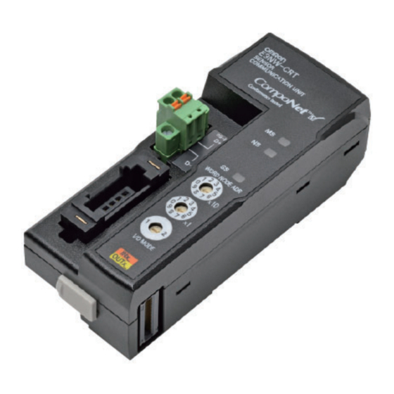
Section 3 Part Names Part Names Part Names and Functions DS-Bus communications Indicators connector This connector connects to an E3NW-DS Distributed Sensor Unit. Communications connector Rotary switches This connector is for CompoNet communications. When connecting to an E3NW- CRT, power is supplied from the communications connector. - Page 42 Section 3 Part Names ■ Indicators The following table describes the indicators. Indicator Indicator Name Status Description color Module status Green Normal operation Flashing Not set up. Fatal error Flashing Non-fatal error Power OFF Network status Green CompoNet online and communications connected. Flashing CompoNet online but not-connected.
-
Page 43: Operating Procedure
Section 3 Operating Procedure Operating Procedure Operating Procedure Step Item Description Mounting the Sensor Mount the Unit to the DIN Track. Mount the Sensor Amplifier Units to the Communications Unit to DIN Track and then link them together. the DIN Track Refer to Installation on page 30 in Section 2 Installation and Connections. -
Page 44: Componet Remote I/O Communications
Section 3 CompoNet Remote I/O Communications CompoNet Remote I/O Communications Assigning Data in the Master E3NW-CRT data is stored in the input area of the CompoNet master. Select one of the following two modes using the rotary switch: I/O mode Operating mode setting Number of connectable Sensors Mode for using explicit communications to monitor the detection... - Page 45 Section 3 CompoNet Remote I/O Communications • Communications Error with Sensor Amplifier Unit: This flag turns ON when the registered number of connected Sensors does not match the number of Sensors available for communications, or when communications with a Sensor Amplifier Unit fails after a connection with the Sensor Amplifier Unit has been established.
- Page 46 Section 3 CompoNet Remote I/O Communications Input Word m + 2 Reserved Error Flags Word m + 3 Read Data Word m + 4 Read Data Word m + 5 Warning Flags *1 S_ERR : Connection Error with Sensor Amplifier Unit This flag turns ON when the registered number of connected Sensors does not match the number of Sensors available for communications, or when communications with a Sensor Amplifier Unit fails after a connection with the Sensor Amplifier Unit has been established.
- Page 47 Section 3 CompoNet Remote I/O Communications Output Area Word n Reserved Sensor Output Number Word n + 1 Multi-command Destination Bit Specification Word n + 2 Command Code Word n + 3 Write Data Word n + 4 Write Data Word n + 5 Reserved *7 Execution Command Bit (trigger output)
- Page 48 Section 3 CompoNet Remote I/O Communications OK: Supported ● Commands NA: Not supported The following table lists the commands. ---: To communication unit Applicable Sensor Output 1 and 2, Amplifier Units Description Read Write Execute or Both Sensor Communications Status Both 0x00 Number of Mounted Sensors...
- Page 49 Section 3 CompoNet Remote I/O Communications OK: Supported, NA: Not supported, ---: To communication unit Applicable Sensor Output 1 and 2, Amplifier Units Description Read Write Execute or Both Light OFF Both 0xC8 Clear Light OFF Both 0xDD Two-point Tuning First Point Outputs 1 and 2 --- 0xC9 Two-point Tuning Second Point...
- Page 50 Section 3 CompoNet Remote I/O Communications ● Command Timing Chart Read, Write, or Execute Command Is Normally Processed A: Turn ON the TRIGGER signal from the host. (Set the Unit Number, Sensor Channel, Command Code, and Command Data at the same time as you turn ON the TRIGGER signal.) B: When the Sensor Communications Unit detects the ON TRIGGER signal from the host, it turns ON the BUSY signal.
-
Page 51: Explicit Message Communications
The specified numbers of bytes for the class ID, instance ID, and attribute ID depend on the master. When a message is sent from an OMRON CompoNet Master Unit, specify the class ID and instance ID in two bytes (four digits), and the attribute ID in one byte (two digits). - Page 52 Section 3 Explicit Message Communications Service Code When the command is completed normally, the leftmost bit of the service code that is specified in the command is turned ON and the service code is stored as follows: Command service code Response service code 10 hex 90 hex...
-
Page 53: Read And Write Commands
Read and Write Commands Read and write commands read and write data to and from the Sensor Communications Unit or connected Sensor Amplifier Units. The command and response formats when using an OMRON Master Unit are given below. ● Command Format Destination... - Page 54 Section 3 Explicit Message Communications ● Response Format • Normal Number of Destination Service code Read Data (read commands only) received bytes network address 008E (Read) 0090 (Write) 2 bytes 2 bytes 2 bytes 4 bytes • Error Number of Destination Service code Error code...
- Page 55 Section 3 Explicit Message Communications ■ Read and Write Commands The following table lists the explicit message read and write commands. Applicable Models E3NX-FA0: FA0, E3NC-LA0: LA0, and E3NC-SA0: SA0 Instance IDs If “Unit No./Output” is specified for the instance ID, use the following value: (Unit number - 1) ×...
- Page 56 Section 3 Explicit Message Communications OK: Supported, NA: Not supported, ---: To communication unit Command Applicable Sensor Amplifier Units Explicit message Function Class Attribute Instance ID Output Mode Reads or writes the Output 0x9C Unit No./ 0xCF Setting Mode Setting. Output Operating Mode Reads or writes the Operating...
- Page 57 Section 3 Explicit Message Communications OK: Supported, NA: Not supported, ---: To communication unit Command Applicable Sensor Amplifier Units Explicit message Function Class Attribute Instance ID Self-Trigger Level Reads or writes the Self Trigger 0x9C Unit No. 0xE1 Level settings. Background Reads or writes the 0x9C...
-
Page 58: Operation Execution Commands
Operation execution commands execute operations such as tuning for connected Sensor Amplifier Units. The command and response formats when using an OMRON Master Unit are given below. Operation execution commands do not have a 4-byte data area like read and write commands. - Page 59 Section 3 Explicit Message Communications ● Response Format • Normal Destination network Number of received bytes Service code address 0096 (fixed) 2 bytes 2 bytes 2 bytes • Error Destination network Number of received bytes Service code Error code address 0094 (fixed) 2 bytes 2 bytes...
- Page 60 Section 3 Explicit Message Communications ■ Operation Execution Commands The following table lists the explicit message operation execution commands. Applicable Models E3NX-FA0: FA0, E3NC-LA0: LA0, and E3NC-SA0: SA0 Instance IDs If “Unit No./Output” is specified for the instance ID, use the following value: (Unit number - 1) ×...
-
Page 61: Error Codes
Section 3 Explicit Message Communications OK: Supported, NA: Not supported, ---: To communication unit Command Applicable Sensor Amplifier Units Explicit message Function Class Instance Attribute One-point Tuning Performs one-point tuning. 0x9E Unit No./ 0xDE Output Flashing Flashes the light. 0x9E Unit No. -
Page 62: Explicit Message Functions Application Example
Section 3 Explicit Message Communications Explicit Message Functions Application Example An example of sending explicit messages using the CS1W-CRM21 is given below. CompoNet Unit, Unit 0 CMND instruction CS1 CPU is used. Unit Unit address: 20 hex Communications Unit: I/O Mode 1, Explicit message node address 00 ●... - Page 63 Section 3 Explicit Message Communications +5: 00C8 hex, Response monitoring time 30 seconds ● Response D02000 + 0: 2802 hex + 1: 0000 hex + 2: 0004 hex + 3: 1000 hex + 4: 0090 hex, Response source node address 0 (00 hex) + Normal completion 90 hex E3NW-CRT User’s Manual...
- Page 64 Section 3 Explicit Message Communications ● Programming Example A20011 000000 BSET #0000 D00000 D02999 Set #0000 in D00000 to D02999. First Cycle MOV #000F D00000 Set #000F in D00000 (number of bytes to send: 15). MOV #000A D00001 Set #0008 in D00001 (number of bytes to receive: 8). Set #0000 in D00002 (destination network address: MOV #0000 D00002 00).
-
Page 65: Using The Distributed Sensor Unit
S e c t i o n 4 Using the Distributed Sensor Unit Models of Sensor Amplifier Units Connectable to a Distributed Sensor Unit Mounting and Removing Distributed Sensor Units Installation Procedure Removal Procedure Installing a DS-Bus Network Precautions for Installing a DS-Bus Network Preparing to Install the Network Connecting the Communications Cables and Connectors... -
Page 66: Models Of Sensor Amplifier Units Connectable To A Distributed Sensor Unit
Section 4 Models of Sensor Amplifier Units Connectable to a Distributed Sensor Unit Models of Sensor Amplifier Units Connectable to a Distributed Sensor Unit This section describes the models and features of the Sensor Amplifier Units that can be connected to an E3NW-DS Distributed Sensor Unit. Type Model number Features... -
Page 67: Mounting And Removing Distributed Sensor Units
Section 4 Mounting and Removing Distributed Sensor Units Mounting and Removing Distributed Sensor Units This section describes how to mount an E3NW-DS Distributed Sensor Unit and Sensor Amplifier Units to a DIN Track and how to remove them. Refer to Dimensions on page 24 in Section 2 Installation and Connections for dimensions of each Distributed Sensor Units. -
Page 68: Removal Procedure
Section 4 Mounting and Removing Distributed Sensor Units Secure the enclosed DIN Track End Plates (PFP-M) onto the ends so that there is no space between them and the Units. Finally, attach the protective cap Protective cap DIN Track you removed in step 3 to the End Plate Sensor Amplifier Unit on the far right end. -
Page 69: Installing A Ds-Bus Network
Section 4 Installing a DS-Bus Network Installing a DS-Bus Network This section describes how to install a DS-Bus network. Precautions for Installing a DS-Bus Network This section provides basic precautions for installing a DS-Bus network. ● Precautions for Installing a Network •... -
Page 70: Preparing To Install The Network
Section 4 Installing a DS-Bus Network Preparing to Install the Network Prepare the following equipment. Item Remarks DS-Bus communications cable Use the recommended product that is given below. Sensor Communications Unit Enclosed with the E3NW Series Sensor Communications Unit. DS-Bus Communications Connector Distributed Sensor Unit Enclosed with the E3NW-DS Distributed Sensor Unit. -
Page 71: Connecting The Communications Cables And Connectors
Section 4 Installing a DS-Bus Network Connecting the Communications Cables and Connectors ● E3NW-series Sensor Communications Unit Connect the communications cable to the DS-Bus communications connector on the Communications Unit. Clamp a ferrite core (enclosed with the Distributed Sensor Unit) to the communications cable. - Page 72 Section 4 Installing a DS-Bus Network ● E3NW-DS Distributed Sensor Unit Connect the D+ and D− signal lines and shield wire of the communications cable to the power supply/communications connector on the Sensor Communications Unit. Clamp a ferrite core (enclosed with the Distributed Sensor Unit) to the communications cable. Connect the shield wire on the communications cable between Distributed Sensor Units to the −V terminal on only one of the Distributed Sensor Units.
-
Page 73: Distributed Sensor Unit Power Supply Specifications And Connections
Between the outputs and AC power supply and between the outputs and case ground We recommend using an OMRON S8JX-series power supply for the Unit power supply. • When calculating the output current for the Unit power supply, always include the current consumption of the E3NW-DS and the current consumption of all Sensor Amplifier Units in the Unit power supply consumption current. -
Page 74: Connecting The Unit Power Supply
Phoenix Contact Co., Ltd. No. 1204436) or CRIMPFOX ZA3 Series H0.5/16 orange 0.5 mm /AWG20 Crimper PZ1.5 (product Weidmueller Japan Co., Ltd. No. 900599) We recommend the following screwdriver for the removal of ferrules. Model number Manufacturer XW4Z-00C OMRON Corporation E3NW-CRT User’s Manual... -
Page 75: General Specifications Of The Distributed Sensor Unit
Section 4 General Specifications of the Distributed Sensor Unit General Specifications of the Distributed Sensor Unit The following table gives the general specifications of the E3NW-DS Distributed Sensor Unit. Item Specifications and Performances Unit power supply voltage 24 VDC (20.4 to 26.4 V) Power and current 2 W max. -
Page 76: Hardware Specifications Of The Distributed Sensor Unit
Section 4 Hardware Specifications of the Distributed Sensor Unit Hardware Specifications of the Distributed Sensor Unit Status Indicators These indicators show the current status of the E3NW-DS. ● RUN Indicator This indicator shows the operating status. Color Status Description Green The power is OFF or one of the following errors has occurred: Rotary switch setting error, WDT error (timeout), hardware error, or RAM check error... -
Page 77: Unit Address Setting Switch
Section 4 Hardware Specifications of the Distributed Sensor Unit Unit Address Setting Switch This switch sets the Unit address (as a decimal number) of the E3NW-DS on the DS-Bus network. The setting range is 1 to 8. (Factory setting: 1) If multiple Distributed Sensor Units are connected to the Sensor Communications Unit, set the addresses of the Distributed Sensor Units in order starting from 1. -
Page 78: Ds-Bus Network Termination Setting Switch
Section 4 Hardware Specifications of the Distributed Sensor Unit DS-Bus Network Termination Setting Switch This switch turns the communications terminating resistance ON or OFF on the DS-Bus network. Termination setting switch Turn ON the DS-Bus termination setting switch for the last Distributed Sensor Unit on the DS-Bus network. -
Page 79: Communications And Power Supply Connector
Section 4 Hardware Specifications of the Distributed Sensor Unit Communications and Power Supply Connector Connect the power cable from the Unit power supply and DS-Bus communications cable to this connector. • Connector type: Four-pin spring cage connector with lock screws +V terminal Name Specification... - Page 80 Section 4 Hardware Specifications of the Distributed Sensor Unit E3NW-CRT User’s Manual...
- Page 81 S e c t i o n 5 Appendices Command Descriptions and Data Formats Command Response Time (Reference Values) Troubleshooting CompoNet Device Profile Device Profile E3NW-CRT User’s Manual...
- Page 82 Section 5 Command Descriptions and Data Formats Command Descriptions and Data Formats This section describes the commands and data formats for the Sensor Communications Unit. The data formats are the same for explicit message communications and I/O command communications in I/O Mode 2. However, when using explicit messages, 4-byte data is expressed in little endian format.
- Page 83 Section 5 Command Descriptions and Data Formats ● Number of Mounted Sensors This command reads the current number of Sensors, including Dummy Sensors. Description Data 00 to 04 Number of Mounted Sensors Data range: 0 (00000000 hex) to 16 (00000010 hex) 05 to 31 No applicable data Always 0...
- Page 84 Section 5 Command Descriptions and Data Formats ● Dummy Sensor Response Setting This command registers a Dummy Sensor. If a Dummy Sensor is registered as Unit 1 (i.e., if bit 00 is 1), the actual first Unit (i.e., the leftmost Sensor Amplifier Unit) will be Unit 2. You must restart the Sensor Communications Unit for any changes to the Dummy Sensor Settings to take affect.
- Page 85 Section 5 Command Descriptions and Data Formats ● Continuous Read Detection Level This command continuously reads the Detection Level (incident light level) of the Sensor Amplifier Unit that corresponds to the specified unit number and output number. This is not supported by explicit messages. The data is given as the two’s complement of a 4-byte (8-digit) hexadecimal value.
- Page 86 Section 5 Command Descriptions and Data Formats ● Threshold Setting 2 This command reads or writes Threshold Value 2 of the Sensor Amplifier Unit that corresponds to the specified unit number. Threshold Value 2 is the high threshold value in area detection mode. The data is given as the two’s complement of a 4-byte (8-digit) hexadecimal value.
- Page 87 Section 5 Command Descriptions and Data Formats ● Output Mode Setting This command reads or writes the Output Mode of the Sensor Amplifier Unit that corresponds to the specified unit number and output number. Data Description Output 1 Output 2 00 or 01 Output Mode 0: Normal detection mode...
- Page 88 Section 5 Command Descriptions and Data Formats ● Timer Time 1 This command reads or writes Timer Time 1 of the Sensor Amplifier Unit that corresponds to the specified unit number and output number. Timer Time 1 is assigned to the ON delay or one-shot timer. Description Data 00 to 15...
- Page 89 Section 5 Command Descriptions and Data Formats ● Display Switch This command sets the display on the Sensor Amplifier Unit that corresponds to the specified unit number. Description Data Display Switch 0: Threshold value/detection level [Std] 1: Detection level margin for the threshold value [PEr] 2: Incident light peak minimum value and interrupted light bottom maximum value [P-b] 3: Bar display [bAr]...
- Page 90 Section 5 Command Descriptions and Data Formats ● Eco Mode This command sets the Eco Mode of the Sensor Amplifier Unit that corresponds to the specified unit number. Description Data Eco Mode 0: Eco Mode OFF 1: Eco Mode ON 2: Eco Mode LO 02 to 31 No applicable data...
- Page 91 Section 5 Command Descriptions and Data Formats ● Hysteresis Width 2 This command sets Hysteresis Width 2 of the Sensor Amplifier Unit that corresponds to the specified unit number. Description Data 00 to 31 Hysteresis Width 2 Data range: 0 (00000000 hex) to 9999 (0000270F hex) ●...
- Page 92 Section 5 Command Descriptions and Data Formats ● Zero Reset This command sets the Zero Reset of the Sensor Amplifier Unit that corresponds to the specified unit number. Description Data Zero Reset 0: Zero reset OFF 1: Zero reset ON 01 to 31 No applicable data Always 0...
- Page 93 Section 5 Command Descriptions and Data Formats ● Percentage Tuning Setting This command sets Percentage Tuning for the Sensor Amplifier Unit that corresponds to the specified unit number and output number. Description Data Percentage Tuning Setting 0: Percentage tuning setting OFF 1: Percentage tuning setting ON 01 to 31 No applicable data...
- Page 94 Section 5 Command Descriptions and Data Formats ● One-point Tuning This command executes one-point tuning for the Sensor Amplifier Unit that corresponds to the specified unit number and output number. This must be performed at least 3 seconds after a full auto tuning setup is executed with no workpiece.
- Page 95 Section 5 Command Descriptions and Data Formats ● Background Suppression This command sets Background Suppression of the Sensor Amplifier Unit that corresponds to the specified unit number. Description Data Background Suppression 0: Background suppression OFF 1: Background suppression ON 01 to 31 No applicable data Always 0 E3NW-CRT...
- Page 96 Section 5 Command Response Time (Reference Values) Command Response Time (Reference Values) The time required from when a command is sent to obtain the incident light level of input 1 of Sensor Amplifier Unit 1 connected to an E3NW-CRT Communications Unit until a response is received is approximately 6 ms.
- Page 97 Section 5 Troubleshooting Troubleshooting The following table lists the possible indicator status, possible causes, and remedies for problems. Status Possible cause Remedy MS and NS Power is not being supplied. Supply power from the CompoNet communications indicators not lit connector. The power voltage is outside Maintain the power voltage within the allowable range.
- Page 98 Section 5 Troubleshooting Status Possible cause Remedy SS indicator lit One of the connected Sensor Replace the faulty Sensor Amplifier Unit. Amplifier Units is faulty. You can determine which Sensor Amplifier Unit is faulty by checking the number of Sensors available for communications.
- Page 99 Section 5 CompoNet Device Profile CompoNet Device Profile Device Profile You can use an explicit command to check the device profile. • Class ID 0x01 • Instance ID 0x01 Attribute ID Contents Get Set Value Vendor Product type Product code 1657 Revision Status (bits...
- Page 100 Section 5 Revision History Revision History A manual revision code appears as a suffix to the catalog number at the bottom of the front and back covers of this manual. Cat. No. E430-E1-04 (Web Version 3) Revision code Reprint code (on the back cover only) Revision Reprint code Date...
- Page 102 The Netherlands Hoffman Estates, IL 60169 U.S.A Tel: (1) 847-843-7900/Fax: (1) 847-843-7787 Tel: (31)2356-81-300/Fax: (31)2356-81-388 © OMRON Corporation 2013 All Rights Reserved. OMRON (CHINA) CO., LTD. OMRON ASIA PACIFIC PTE. LTD. In the interest of product improvement, Room 2211, Bank of China Tower, No.