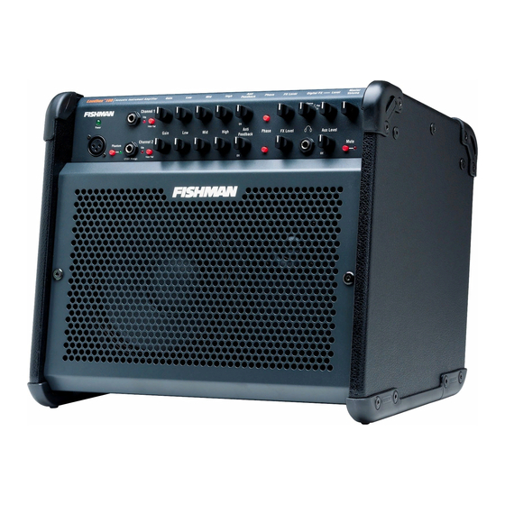
Fishman LOUDBOX 100 Replacement
Head cap chassis replacement
Hide thumbs
Also See for LOUDBOX 100:
- Owner's manual (16 pages) ,
- User manual (20 pages) ,
- Training manual (3 pages)
Advertisement
Quick Links
Required Tools & Parts
4mm Hex Wrench, #2 Phillips Screwdriver
Loudbox Performer Head Cap Chassis - P/N ACC-000-000 or Loudbox 100 Head Cap Chassis - P/N ACC-000-000
Remove Head Cap Chassis
1. Using a 4mm hex wrench, remove the (6) bolts (red arrows) securing the Head Cap Chassis.
2. Lift Head Cap Chassis Straight up from cabinet
and place on side as shown.
LOUDBOX 100 & LOUDBOX PERFORMER
HEAD CAP CHASSIS REPLACEMENT
Warning
This document is accurate for current revisions of the Loudbox Performer and all
revisions of the Loudbox 100. Older revisions of the Loudbox Performer use a differ-
ent Head Cap Chassis and are not compatible with this document. Current revisions
of the Performer have a headphone output on the Head Cap. If you have an older
model, without the headphone output, please contact support@fi shman.com for
more information before proceeding with this repair.
2
Advertisement

Related Manuals for Fishman LOUDBOX 100


Summary of Contents for Fishman LOUDBOX 100
- Page 1 Required Tools & Parts 4mm Hex Wrench, #2 Phillips Screwdriver Loudbox Performer Head Cap Chassis - P/N ACC-000-000 or Loudbox 100 Head Cap Chassis - P/N ACC-000-000 Remove Head Cap Chassis 1. Using a 4mm hex wrench, remove the (6) bolts (red arrows) securing the Head Cap Chassis.
- Page 2 LOUDBOX 100 & LOUDBOX PERFORMER HEAD CAP CHASSIS REPLACEMENT Disconnect Head Cap Chassis from Cabinet 1. Follow red and black wires from cabinet to chassis and remove connector as shown in A. 2. Remove green and yellow ground wire from chassis as shown in B. Set chassis aside.
- Page 3 LOUDBOX 100 POWER AMPLIFIER CHASSIS REPLACEMENT Warning The Loudbox 100 Power Amplifi er Chassis part is specifi ed either for 120V or 240V function. Make sure, before continuing with this installation, that the correct replacement part has been selected. Required Tools and Parts #2 Phillips Screwdriver, 4mm Hex Wrench Loudbox 100 120V Power Amplifi...
- Page 4 LOUDBOX 100 POWER AMPLIFIER CHASSIS REPLACEMENT Disconnect Chassis from Cabinet JP10 JP10 JP5: blue/yellow/red/black JP6: blue/gray/blue JP8: alternating black/red JP9: brown/white/blue JP10: red/brown/orange/white/black 1. Remove fi ve connectors from Chassis PCB at board locations JP5, JP6, JP8, JP9 and JP10.
- Page 5 3. Mount head cap to cabinet as shown in the Reassembly section of same guide. Connect and Reassemble Amplifi er 1. Make all 5 connections from Loudbox 100 to Power Amplifi er Chassis (JP5, JP6, JP8, JP9 and JP10) as in disassembly.