Table of Contents
Advertisement
Cisco ASR 1000 Series Aggregation
Services Routers Hardware Installation
and Initial Configuration Guide
November 2008
Americas Headquarters
Cisco Systems, Inc.
170 West Tasman Drive
San Jose, CA 95134-1706
USA
http://www.cisco.com
Tel: 408 526-4000
800 553-NETS (6387)
Fax: 408 527-0883
Text Part Number: OL-13208-03
Advertisement
Table of Contents
Troubleshooting

Related Manuals for Cisco ASR 1000 Series


Summary of Contents for Cisco ASR 1000 Series
- Page 1 Cisco ASR 1000 Series Aggregation Services Routers Hardware Installation and Initial Configuration Guide November 2008 Americas Headquarters Cisco Systems, Inc. 170 West Tasman Drive San Jose, CA 95134-1706 http://www.cisco.com Tel: 408 526-4000 800 553-NETS (6387) Fax: 408 527-0883 Text Part Number: OL-13208-03...
- Page 2 MeetingPlace Chime Sound, MGX, Networkers, Networking Academy, Network Registrar, PCNow, PIX, PowerPanels, ProConnect, ScriptShare, SenderBase, SMARTnet, Spectrum Expert, StackWise, The Fastest Way to Increase Your Internet Quotient, TransPath, WebEx, and the WebEx logo are registered trademarks of Cisco Systems, Inc.
-
Page 3: Table Of Contents
C H A P T E R Cisco ASR 1000 Series Route Processor Cisco ASR 1000 Series Route Processor Features Cisco ASR 1000 Series Aggregation Services Routers Hardware Installation and Initial Configuration Guide OL-13208-03 C O N T E N T S... - Page 4 Site Environmental Requirements Physical Characteristics Floor Loading Considerations Site Power Guidelines Electrical Circuit Requirements Site Cabling Guidelines Asynchronous Terminal Connections Interference Considerations Cisco ASR 1000 Series Aggregation Services Routers Hardware Installation and Initial Configuration Guide 2-13 2-14 2-16 2-17 2-17 2-18 2-23...
- Page 5 Connecting Shared Port Adapter Cables Connecting Console and Auxiliary Port Cables Connecting the Ethernet Management Port Cable Connecting Power to Cisco ASR 1006 Router Cisco ASR 1000 Series Aggregation Services Routers Hardware Installation and Initial Configuration Guide OL-13208-03 3-14 3-14...
- Page 6 Connecting Network Management and Signal System Cables Auxiliary Connection Cisco ASR 1002 Router Overview and Installation C H A P T E R Cisco ASR 1002 Router Description Cisco ASR 1000 Series Aggregation Services Routers Hardware Installation and Initial Configuration Guide 4-29 4-30 5-10 5-10...
- Page 7 C H A P T E R Checking Conditions Prior to System Startup Verifying Power Supply Operation Powering Up the Cisco ASR 1000 Series Routers Cisco ASR 1000 Series Aggregation Services Routers Hardware Installation and Initial Configuration Guide OL-13208-03 6-10 6-12...
- Page 8 Removing and Replacing the Cisco ASR 1000 Series RP1 Internal Hard Drive Cisco ASR 1000 Series RP1 Spare Hard Drive Accessory Kit Removing the Cisco ASR 1000 Series RP1 and Internal Hard Drive from the Cisco ASR 1000 Series Router...
- Page 9 Cisco ASR 1002 Router Console Port Signals and Pinouts Cisco ASR 1002 Router Auxiliary Port Signals and Pinouts Cisco ASR 1002 Router BITS Port Signals and Pinouts Cisco ASR 1000 Series Aggregation Services Routers Hardware Installation and Initial Configuration Guide OL-13208-03 8-48...
- Page 10 Overview of the Password Recovery Procedure Details of the Password Recovery Procedure L O S S A R Y N D E X Cisco ASR 1000 Series Aggregation Services Routers Hardware Installation and Initial Configuration Guide B-13 B-13 B-14 B-14...
- Page 11 Preface This preface discusses the objectives, audience, and organization of the Cisco ASR 1000 Series Aggregation Services Routers Hardware Installation and Initial Configuration Guide. The following sections are in this preface: Document Revision History, page xi • Document Objectives, page xii •...
-
Page 12: Preface
Document Objectives Document Objectives This publication describes the installation of the Cisco ASR 1000 Series Aggregation Services Routers, replacement or upgrading of field-replaceable units (FRUs), and troubleshooting of the Cisco ASR 1000 Series Routers hardware. The purpose of this guide is to enable the safe and efficient installation of the Cisco ASR 1000 Series Aggregation Services Routers. -
Page 13: Safety Warnings And Cautions
Index Safety Warnings and Cautions Most safety warnings for the Cisco ASR 1000 Series Routers are placed in relevant sections throughout the document. For translated safety warnings, see the Regulatory Compliance and Safety Information for the Cisco 1000 Series Aggregation Services Routers. Below is Statement 1071, the Warning Definition statement, complete with translated warnings. - Page 14 å forhindre ulykker. Bruk nummeret i slutten av hver advarsel for å finne oversettelsen i de oversatte sikkerhetsadvarslene som fulgte med denne enheten. TA VARE PÅ DISSE INSTRUKSJONENE Cisco ASR 1000 Series Aggregation Services Routers Hardware Installation and Initial Configuration Guide Preface OL-13208-03...
- Page 15 Använd det nummer som finns i slutet av varje varning för att hitta dess översättning i de översatta säkerhetsvarningar som medföljer denna anordning. SPARA DESSA ANVISNINGAR Cisco ASR 1000 Series Aggregation Services Routers Hardware Installation and Initial Configuration Guide OL-13208-03...
- Page 16 Brug erklæringsnummeret efter hver advarsel for at finde oversættelsen i de oversatte advarsler, der fulgte med denne enhed. GEM DISSE ANVISNINGER Cisco ASR 1000 Series Aggregation Services Routers Hardware Installation and Initial Configuration Guide OL-13208-03...
- Page 17 Preface Safety Warnings and Cautions Cisco ASR 1000 Series Aggregation Services Routers Hardware Installation and Initial Configuration Guide xvii OL-13208-03...
-
Page 18: Related Documentation
• All documentation related to the Cisco ASR 1000 Series Routers is listed in the online 1000 Series Aggregation Services Routers Documentation index includes troubleshooting tools and documentation, regulatory compliance and safety information, and installation and replacement information. -
Page 19: Obtaining Documentation And Submitting A Service Request
Preface – Regulatory Compliance and Safety Information for Cisco ASR 1000 Series Aggregation Services Routers information for wide-area network (WAN) interfaces for the Cisco ASR 1000 Series Routers. Cisco ASR 1000 Series shared port adapter documentation. – • Cisco IOS software documentation contains Cisco IOS software configuration information and support. - Page 20 Preface Obtaining Documentation and Submitting a Service Request Cisco ASR 1000 Series Aggregation Services Routers Hardware Installation and Initial Configuration Guide OL-13208-03...
- Page 21 Broadband aggregation—PPPoE/PPPoA aggregation and Service Selection Gateway (SSG) – Low-end Ethernet aggregation – This chapter provides an overview of the Cisco ASR 1000 Series Routers and includes the following information: • Cisco ASR 1000 Series Routers, page 1-2 Cisco ASR 1000 Series Routers Configurations, page •...
-
Page 22: Cisco Asr 1000 Series Routers
The Cisco ASR 1000 Series Aggregation Services Routers use different field replaceable units. The processors are the Cisco ASR 1000 Series Route Processor 1 (RP1), Cisco ASR 1000 Series Embedded Services Processor (Cisco ASR1000-ESP5, Cisco ASR1000-ESP10, and Cisco ASR1000-ESP20), and the Cisco ASR 1000 SPA Interface Processor (SIP). -
Page 23: Cisco Asr 1000 Series Routers Configurations
ESP20), and the shared port adapters. With the exception of the Cisco ASR 1002 Router, all FRUs (Cisco ASR 1000 Series Route Processor 1, Cisco ASR 1000 Series Embedded Services Processor, and SPAs) are designed to work in the different chassis models. -
Page 24: Field-Replaceable Units
Field-Replaceable Units Field-Replaceable Units The Cisco ASR 1000 Series routers are easy to service; many of their major components are field-replaceable units (FRUs). The following is a list of the Cisco ASR 1000 Series Routers FRUs: Cisco ASR 1000 Series Route Processor 1 (RP1) •... -
Page 25: Chassis Slot And Logical Interface Numbering
Chassis Slot and Logical Interface Numbering The Cisco ASR 1000 Series Routers have a slot numbering system located on both sides of the card module location. The chassis slots are physically numbered from zero starting at the bottom of the chassis. - Page 26 Slot FP0 with ASR 1000 Series ESP Slot FP1 with ASR 1000 Series ESP The Cisco ASR 1006 Router contains three Cisco ASR 1000 Series SPA Interface (SIP) supports four subslots for the installation of SPAs. Cisco ASR 1000 Series Aggregaion Services Routers Hardware Installation and Initial Configuration Guide Chapter 1 Cisco ASR 1006 Router —...
-
Page 27: Cisco Asr 1004 Router Slot Numbering
Cisco ASR 1006 Router SPA subslot location. Figure 1-2 Cisco ASR 1004 Router Slot Numbering The Cisco ASR 1004 Router contains two Cisco ASR 1000 Series SPA Interface Processors (SIPs) and supports four subslots for the installation of SPAs. Figure 1-3 shows the Cisco ASR 1004 Router with modules and filler plates installed. -
Page 28: Mac Address Information
These addresses are specific and unique to each port and are not used by other devices in the network. The Cisco ASR 1000 Series Routers assign and control the MAC addresses of its shared port adapters. -
Page 29: Online Insertion And Removal
When you remove or insert a shared port adapter in a Cisco ASR 1000 Series Router, the Control Processor notifies the Cisco ASR1000-RP1, which in turn notifies the forwarding engine control processor (FECP), and then performs as follows: Rapidly scans the midplane for configuration changes. -
Page 30: Environmental Monitoring And Reporting Functions
Critical—An out-of-tolerance temperature or voltage condition exists. The system continues to • operate; however, the system is approaching shutdown. Immediate operator action is required. Cisco ASR 1000 Series Aggregaion Services Routers Hardware Installation and Initial Configuration Guide 1-10 Chapter 1... -
Page 31: Fan Failures
It manages the ESI (Enhanced Serdes Interconnect) which are the datapath links on the midplane connecting the Cisco ASR 1000 Series RP1s, SIPs, and standby ESP modules to the active Cisco ASR 1000 Series Embedded Services Processor. It communicates with the chassis manager on the Cisco ASR 1000 Series Route Processor 1 to report the status and health, including detected hardware failures, ESI status, software process status, and the state of thermal sensors. - Page 32 PEM Vout PEM Vin Temp: PEM Temp: FC Temp: FM Temp: FC V1: VMA V1: VMB V1: VMC Cisco ASR 1000 Series Aggregaion Services Routers Hardware Installation and Initial Configuration Guide 1-12 Chapter 1 Location State Normal Normal Normal Normal...
- Page 33 Cisco products installed in the networking device. Following is sample output of the show inventory command: Router#show inventory NAME: "Chassis", DESCR: "Cisco ASR1004 Chassis" Cisco ASR 1000 Series Aggregaion Services Routers Hardware Installation and Initial Configuration Guide OL-13208-03 Normal Normal...
- Page 34 DRAM and Static RAM (SRAM) on line cards. To display more details than the normal show diag command output, use show diag [slot-number] [details]. Following is sample output of the show diag slot R0 eeprom detail command: Cisco ASR 1000 Series Aggregaion Services Routers Hardware Installation and Initial Configuration Guide 1-14 Chapter 1...
-
Page 35: Cisco Product Identification Standard
This section describes the Cisco products and services product identification standard. This feature provides you with the ability to effectively integrate and manage Cisco products in your network and business operations. Cisco ASR 1000 Series Aggregaion Services Routers Hardware Installation and Initial Configuration Guide OL-13208-03 Cisco Product Identification Standard... -
Page 36: Unique Device Identifier
Cisco product in a network element through a standard interface. Cisco operating systems can view and use this data, allowing you to automate your electronic inventory. Cisco ASR 1000 Series Aggregaion Services Routers Hardware Installation and Initial Configuration Guide 1-16 Chapter 1... -
Page 37: Serial Number Label Location
Note http://www.cisco.com/go/udi/ Serial Number Label Location This section contains graphics of each chassis showing the location of the serial number label. Cisco ASR 1000 Series Aggregaion Services Routers Hardware Installation and Initial Configuration Guide OL-13208-03 Cisco Product Identification Standard 1-17... - Page 38 Figure 1-5 shows the serial number location for the Cisco ASR 1006 Router. Figure 1-5 Cisco ASR 1006 Router Serial Number Label Location SN: XXXNNNNXXXX Cisco ASR 1000 Series Aggregaion Services Routers Hardware Installation and Initial Configuration Guide 1-18 OL-13208-03...
- Page 39 Figure 1-6 shows the serial number label location for the Cisco ASR 1004 Router. Figure 1-6 Cisco ASR 1004 Router Serial Number Label Location SN: XXXNNNNXXXX Cisco ASR 1000 Series Aggregaion Services Routers Hardware Installation and Initial Configuration Guide 1-19 OL-13208-03...
- Page 40 Cisco Product Identification Standard Figure 1-7 shows the serial number label location for the Cisco ASR 1002 Router. Figure 1-7 Cisco ASR 1002 Router Serial Number Label Location Cisco ASR 1000 Series Aggregaion Services Routers Hardware Installation and Initial Configuration Guide 1-20 OL-13208-03...
-
Page 41: Chapter 2 Cisco Asr 1000 Series Routers Components
• Cisco ASR 1000 Series Router Power Supplies, page 2-16 Throughout this document, the term slot refers to a Cisco ASR 1000 Series Router chassis slot. The Note Cisco ASR 1000 Series Route Processor 1, Cisco ASR 1000 Series Embedded Services Processor, and Cisco ASR 1000 Series SPA Interface Processor (SIP), and power supplies plug into these slots. -
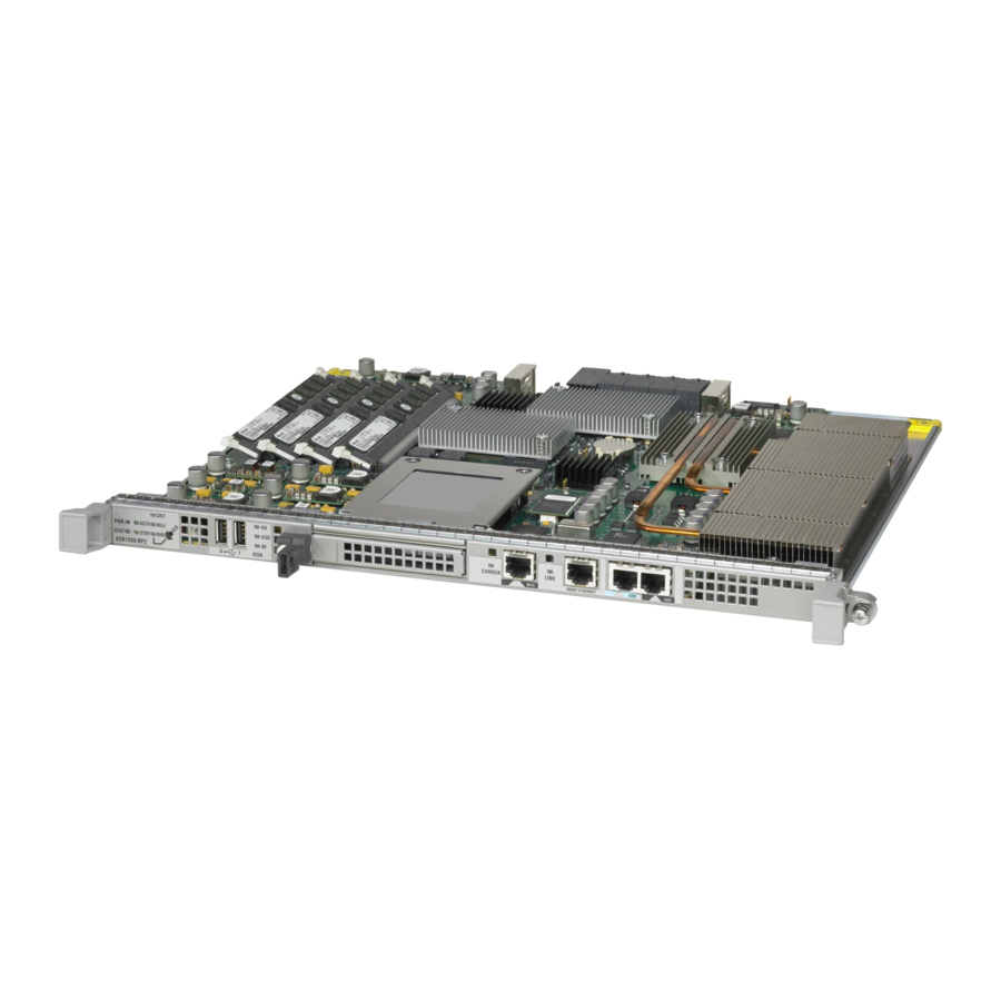
Page 42: Cisco Asr 1000 Series Route Processor Features
• and driving alarm relays located on the power entry modules. The Cisco ASR 1000 Series RP1 module can be configured with either a 40 GB or a 32 GB disk. • The Cisco ASR 1000 Series route processor module consists of a front panel label for indicator and control functions and a separate label for the I/O connectors. - Page 43 Cisco ASR1000-RP1 with faceplate connectors. Figure 2-2 CARRIER CARRIER LED BITS connector LINK LED Cisco ASR 1000 Series Aggregation Services Routers Hardware Installation and Initial Configuration Guide OL-13208-03 Cisco ASR Series 1000 Route Processor Faceplate LEDs and Connectors CRIT ACTV STAT...
- Page 44 Internal USB bootflash LED CARRIER LINK 10/100/1000 RJ-45 Interface LED Cisco ASR 1000 Series Aggregation Services Routers Hardware Installation and Initial Configuration Guide Chapter 2 Cisco ASR 1000 Series Routers Components Color —State Behavior Description Solid green All power requirements are within specification Off, the router is in standby mode.
-
Page 45: How The Cisco Asr1000-Rp1 Alarm Leds Work
Table 2-2 Label BITS MGMT ETHERNET Cisco ASR 1000 Series Aggregation Services Routers Hardware Installation and Initial Configuration Guide OL-13208-03 Cisco ASR 1006 Router DB-25 Pinout Assignments for Alarm Relays, page Cisco ASR 1000 Series Route Processor Connectors Type Description... -
Page 46: Cisco Embedded Asr1000-Rp1 For Cisco Asr 1002 Router
• Enhanced Serdes Interconnect (ESI) at 11.5Gbps. • Gigibit Ethernet switches for EOBC communication and boot-up of the Cisco ASR 1000 Series SPA • Interface (SIP) and Cisco ASR 1000 Series Embedded Services Processor. Runs Cisco IOS network control plane (routing protocol, connections setup) •... - Page 47 Major CRIT Critical BOOT eUSB0 FLASH (BootDisk CARRIER Cisco ASR 1000 Series Aggregation Services Routers Hardware Installation and Initial Configuration Guide OL-13208-03 Embedded Cisco ASR1000-RP1 LEDs ASR 1002 stat crit Cisco Embedded ASR1000-RP1 LEDs in the Cisco ASR 1002 Router Color —State...
- Page 48 Cisco embedded ASR1000-RP1in the Cisco ASR 1002 Router connectors and description. Table 2-4 Cisco Embedded ASR1000-RP1 Connectors Label BITS MGMT Cisco ASR 1000 Series Aggregation Services Routers Hardware Installation and Initial Configuration Guide Chapter 2 Color —State Green Flashing Green Amber Green...
-
Page 49: Cisco Asr 1000 Series Embedded Services Processors
Figure 2-4 FO slot R0 slot Cisco ASR 1000 Series Embedded Services Processors The Cisco ASR 1000 Series Embedded Services Processor (ESP) is based on the Cisco QuantumFlow Processor for next-generation forwarding and queuing. The Cisco ASR 1000 Series ESPs: •... - Page 50 Cisco ASR 1000 Series Embedded Services Processors The Cisco ASR 1000 Series routers support the following Cisco ASR 1000 Series Embedded Services Processors: • Cisco ASR1000-ESP5 The Cisco ASR1000-ESP5 does not support redundant configurations. Note • Cisco ASR1000-ESP10 Cisco ASR1000-ESP10-N—The Cisco ASR1000 Embedded Services Processor 10G Non Crypto •...
- Page 51 F0 in the Cisco ASR 1002 Router only The Cisco ASR 1000 Series Embedded Services Processor (ESP) consists of a front panel label for indicator and control functions. The Cisco ASR 1000 Series Embedded Services Processor model number labeling is located next to the left card module handle. The module also contains card handles to assist in insertion or removal of the module.
- Page 52 LED Label Power STAT System status ACTV Active STBY Standby Cisco ASR 1000 Series Aggregation Services Routers Hardware Installation and Initial Configuration Guide 2-12 Cisco ASR1000-ESP10 Faceplate LEDs STAT ASR1000-ESP10 Color Behavior Description Solid green All power requirements are within specification The ESP is not powered on.
-
Page 53: Cisco Asr 1000 Series Spa Interface Processor
This section describes the SPA interface processor for the Cisco ASR 1006 and Cisco ASR 1004 routers and the Cisco embedded ASR1000-SIP10 for the Cisco ASR 1002 Router. The Cisco ASR 1000 Series SPA Interface Processor for the Cisco ASR 1006 and Cisco ASR 1004 routers: •... -
Page 54: Shared Port Adapters
2 half-height and 1 full-height combination that does not exceed 64 ports Figure 2-8 shows the slot numbering for the shared port adapters on the Cisco ASR 1000 Series SPA Interface for the Cisco ASR 1006 Router and Cisco ASR 1004 Router. - Page 55 • Three removable half height SPAs on Bay 1, 2, and 3 The fourth SPA which is a built-in 4xGE SPA on Bay 0 located on the Cisco ASR 1000 Series RP1 • The shared port adapters on the Cisco ASR1002-SIP10 support online insertion and removal.
-
Page 56: Cisco Asr 1000 Series Router Power Supplies
The system fans are inside the power supply unit and must spin for cooling. No Cisco ASR 1000 Series Router will operate for more than five minutes without two power supplies installed. Since all the system fans can be powered by one power supply, it is not required for the second power supply unit to be powered on, but it must be installed. -
Page 57: Dc Power System Input Requirements For Cisco Asr 1000 Series Routers
All Cisco ASR 1000 Series Router AC power supplies require a 20 AMP circuit breaker. Note AC and DC Power Supply Types The AC and DC power supplies for the Cisco ASR 1000 Series Routers support different types of power supply switches. Standby or an On/Off switch). -
Page 58: Power Supplies For Cisco Asr 1006 Router
Cisco ASR 1000 Series Router Power Supplies Table 2-10 AC and DC Power Supply System Rating Specifications for the Cisco ASR 1000 Series Routers Description Power supply declared ratings Nominal line frequency rating Power Supplies for Cisco ASR 1006 Router The Cisco ASR 1006 Router can support up to 1200W output (AC and DC input). - Page 59 DB-25 alarm connector Tie-wrap tab AC power supply captive screw Figure 2-11 shows the AC power supplies LEDs and DB-25 Alarm connector. Cisco ASR 1000 Series Aggregation Services Routers Hardware Installation and Initial Configuration Guide OL-13208-03 Table 2-11. OUTPUT INPUT INPUT...
- Page 60 Cisco ASR 1006 Router AC Power Supply LEDs LED Label INPUT OK Power supply activity Cisco ASR 1000 Series Aggregation Services Routers Hardware Installation and Initial Configuration Guide 2-20 Cisco ASR 1006 Router AC Power Supply LEDs and DB-25 Alarm Connector O U T P U T...
-
Page 61: Dc Power Supply Leds And Connectors For Cisco Asr 1006
1006 Router supports up to two power supplies. The power supply LEDs and connectors on the rear of the chassis are described in the Cisco ASR 1000 Series Aggregation Services Routers Hardware Installation and Initial Configuration Guide OL-13208-03 Cisco ASR 1000 Series Router Power Supplies... - Page 62 OUTPUT FAIL Power supply activity Cisco ASR 1000 Series Aggregation Services Routers Hardware Installation and Initial Configuration Guide 2-22 -48/-60V This unit might have more than one power supply connection. All connections must be removed to de-energize the unit.
-
Page 63: Power Supplies For Cisco Asr 1004 Router
Router. The power supply module contains three fans mounted in the power supply module. A total of six fans are used to cool the ASR 1004 system and power supply. The airflow direction is front to back. Cisco ASR 1000 Series Aggregation Services Routers Hardware Installation and Initial Configuration Guide OL-13208-03... - Page 64 AC power supply LEDs DB-25 alarm connector Cisco ASR 1000 Series Aggregation Services Routers Hardware Installation and Initial Configuration Guide 2-24 Table 2-14. Cisco ASR 1004 Router AC Power Supply...
- Page 65 LED Label INPUT OK Power supply activity Cisco ASR 1000 Series Aggregation Services Routers Hardware Installation and Initial Configuration Guide OL-13208-03 Cisco ASR 1004 Router AC Power Supply LEDs and DB -25 Alarm Connector O U T P U T...
-
Page 66: Cisco Asr Router 1004 Dc Power Supply
ASR 1004 Router supports up to two power supplies. The power supply LEDs and connectors on the rear of the chassis are described in the Cisco ASR 1000 Series Aggregation Services Routers Hardware Installation and Initial Configuration Guide 2-26 Color... - Page 67 LED Label INPUT OK A bi-color LED indicates presence of input voltage Cisco ASR 1000 Series Aggregation Services Routers Hardware Installation and Initial Configuration Guide OL-13208-03 Cisco ASR 1004 Router DC Power Supply Color Description Green LED illuminates green to signal that the DC power supply input voltage is greater than–43.5VDC at turn-on and remains green down...
-
Page 68: Power Supplies For Cisco Asr 1002 Router
AC input side contains a front panel with provisions for mounting screw, two built-in handles to extract the power supply, three status LEDs, and fans for power supply and system cooling. Cisco ASR 1000 Series Aggregation Services Routers Hardware Installation and Initial Configuration Guide 2-28... -
Page 69: Cisco Asr 1002 Router Ac Power Supply
ASR 1002 Router supports up to two power supplies. The power supply LEDs and connectors on the rear of the chassis are described in Cisco ASR 1000 Series Aggregation Services Routers Hardware Installation and Initial Configuration Guide OL-13208-03 Cisco ASR 1000 Series Router Power Supplies 2-31—The DC power supply operates between... - Page 70 FAN OK Bi-color LED indicates fan status OUTPUT FAIL Power supply activity Cisco ASR 1000 Series Aggregation Services Routers Hardware Installation and Initial Configuration Guide 2-30 Cisco ASR 1002 Router AC Power Supply OUTPUT INPUT FAIL This unit might have more than one power supply connection.
-
Page 71: Cisco Asr 1002 Router Dc Power Supply
ASR 1002 Router supports up to two power supplies. The power supply LEDs and connectors on the rear of the chassis are described in the Cisco ASR 1000 Series Aggregation Services Routers Hardware Installation and Initial Configuration Guide OL-13208-03 Cisco ASR 1002 Router AC Power Supply Output Voltage Alarm Range Minimum 10.0 to 11.2V... - Page 72 A bi-color LED indicates power supply fan status OUTPUT FAIL Power supply activity Cisco ASR 1000 Series Aggregation Services Routers Hardware Installation and Initial Configuration Guide 2-32 Cisco ASR 1002 Router DC Power Supply OUTPUT INPUT FAIL This unit might have more than one power supply connection.
- Page 73 Output Voltage Minimum Nominal Maximum Output Current Minimum Maximum Cisco ASR 1000 Series Aggregation Services Routers Hardware Installation and Initial Configuration Guide OL-13208-03 Cisco ASR 1002 Router DC Power System Input Minimum –40.5 –55 Table 2-22 Cisco ASR 1002 Router DC Power System Output Voltage and Current +12 VDC –11.80 VDC...
- Page 74 Chapter 2 Cisco ASR 1000 Series Routers Components Cisco ASR 1000 Series Router Power Supplies Cisco ASR 1000 Series Aggregation Services Routers Hardware Installation and Initial Configuration Guide 2-34 OL-13208-03...
- Page 75 The environmental conditions your installation site must meet to maintain normal operation This chapter contains important safety information you should know before working with the Cisco ASR 1000 Series Aggregation Services Routers and guides you through the process of preparing your site for router installation.
-
Page 76: Safety Recommendations
Do not wear loose clothing, jewelry (including rings and chains), or other items that could get caught • in the chassis. Fasten your tie or scarf and sleeves. The Cisco ASR 1000 Series Routers operate safely when it is used in accordance with its marked • electrical ratings and product usage instructions. -
Page 77: Cautions And Regulatory Compliance Statements For Nebs
OSP cabling. The addition of primary protectors is not sufficient protection in order to connect these interfaces metallically to OSP wiring. Cisco ASR 1000 Series Aggregation Services Routers Hardware Installation and Initial Configuration Guide OL-13208-03 Safety Compliance and NEBS Requirements... -
Page 78: Standard Warning Statements
Warning Ultimate disposal of this product should be handled according to all national laws and regulations. Statement 1040 Cisco ASR 1000 Series Aggregation Services Routers Hardware Installation and Initial Configuration Guide Chapter 3 Preparing Your Site for Installation Regulatory, Compliance, and Safety document. - Page 79 Statement 1028 Warning The plug-socket combination must be accessible at all times, because it serves as the main disconnecting device. Statement 1019 Cisco ASR 1000 Series Aggregation Services Routers Hardware Installation and Initial Configuration Guide OL-13208-03 Standard Warning Statements...
- Page 80 Do not touch or bridge the metal contacts on the battery. Unintentional discharge of the batteries can Warning cause serious burns. Statement 341 Cisco ASR 1000 Series Aggregation Services Routers Hardware Installation and Initial Configuration Guide Chapter 3 Preparing Your Site for Installation...
-
Page 81: Site Planning
Do not push any objects into the openings of your system components. Doing so can cause fire or • electric shock by shorting out interior components. Cisco ASR 1000 Series Aggregation Services Routers Hardware Installation and Initial Configuration Guide OL-13208-03 Site Planning... -
Page 82: Site Selection Guidelines
Physical Characteristics Be familiar with the physical characteristics of the Cisco ASR 1000 Series Router to assist you in placing the system in the proper location. Cisco ASR 1000 Series Aggregation Services Routers Hardware Installation and Initial Configuration Guide... - Page 83 – – Chassis width meets EIA-310 19inch (17.25/438.15mm) wide with rack brackets Cable-management brackets at each Cisco ASR 1000 Series SPA Interface (SIP) locations can – hold 16 ports of STP/UTP RJ 45 cables Cable-management brackets allow for 1.5 inch bend radii for cables –...
-
Page 84: Floor Loading Considerations
Each Cisco 1000 Series Router requires a dedicated electrical circuit. If you equip it with dual power feeds, provide a separate circuit for each power supply to avoid compromising the power redundancy feature. Cisco ASR 1000 Series Aggregation Services Routers Hardware Installation and Initial Configuration Guide 3-10 Chapter 3... - Page 85 Preparing Your Site for Installation The Cisco ASR 1000 Series Routers can be powered by a DC or AC source. Ensure that the equipment grounding is present and observe power strip ratings. Make sure that the total ampere rating of all products plugged into the power strip does not exceed 80% of the rating.
-
Page 86: Site Cabling Guidelines
Site Planning Table 3-7 AC and DC Power Supply System Rating Specifications for the Cisco ASR 1000 Series Routers Description Power supply declared ratings Line frequency rating Site Cabling Guidelines This section contains guidelines for wiring and cabling at your site. When preparing your site for network connections to the Cisco 1000 Series Router, consider the type of cable required for each component, and the cable limitations. -
Page 87: Asynchronous Terminal Connections
Cisco ASR 1000 Series Aggregation Services Routers. Table 3-8 EMC Standards CE marking Cisco ASR 1000 Series Aggregation Services Routers Hardware Installation and Initial Configuration Guide OL-13208-03 EMC Standards FCC 47 CFR Part 15 Class A VCCI Class A... -
Page 88: Rack-Mounting And Location Guidelines
If the rack is provided with stabilizing devices, then install the stabilizers before mounting or • servicing the unit in the rack. Cisco ASR 1000 Series Aggregation Services Routers Hardware Installation and Initial Configuration Guide 3-14 EMC Standards IEC 60950-1 AS/NZS 60950.1... -
Page 89: Rack Selection Guidelines
Keep at least 3 feet of clear space in front and behind the rack. This space ensures that you can remove the Cisco 1000 Series Router components and perform routine maintenance and upgrades easily. Cisco ASR 1000 Series Aggregation Services Routers Hardware Installation and Initial Configuration Guide OL-13208-03... - Page 90 Series Router. The Cisco 1000 Series Router airflow direction is front to back with ambient air drawn in from the venting located on the chassis front sides. Cisco ASR 1000 Series Aggregation Services Routers Hardware Installation and Initial Configuration Guide 3-16...
-
Page 91: Site Planning Checklist
The site air conditioning system can compensate for the heat dissipation of the Cisco ASR 1000 Series. The floor space that the Cisco ASR 1000 Series Routers occupy can support the weight of the system). Electrical service to the site complies with the requirements. -
Page 92: Electrical Safety
Before beginning any procedures requiring access to the chassis interior, locate the emergency • power-off switch for the room in which you are working. Cisco ASR 1000 Series Aggregation Services Routers Hardware Installation and Initial Configuration Guide 3-18 ESD Chassis Grounding Stud... -
Page 93: Receiving A Cisco Asr 1000 Series Router
Each Cisco ASR1000 Series chassis is shipped in a container that is strapped to a pallet as illustrated in Figure 3-2. Cisco ASR 1000 Series Aggregation Services Routers Hardware Installation and Initial Configuration Guide OL-13208-03 Receiving a Cisco ASR 1000 Series Router... -
Page 94: Chassis-Lifting Guidelines
Do not remove installed components from the chassis. • Always disconnect all external cables before lifting or moving the chassis. • Cisco ASR 1000 Series Aggregation Services Routers Hardware Installation and Initial Configuration Guide 3-20 Cisco ASR 1000 Series Router Packaged for Shipping Chapter 3... -
Page 95: Tools And Equipment
After you have unpacked the system verify that you have received all of the required components. Using the packing list as a guide, take the following steps to check the contents of the Cisco ASR 1000 Series Router shipping container: Check the contents of the boxes containing accessory items. - Page 96 Cisco Aggregation Services Router 1000 Series document, and the Cisco Aggregation Services Router 1000 Series Documentation Roadmap that contains documentation titles and the URLs to them online. See also the Cisco ASR 1000 Series Aggregation Services Routers Hardware Installation and Initial Configuration Guide 3-22 Description...
-
Page 97: Cisco Asr 1000 Series Router Installation Checklist
To assist you with your installation and to provide a historical record of what was done by whom, photocopy the Cisco ASR 1000 Series Router Installation Checklist. Use this to indicate when each procedure or verification is completed. When the checklist is completed, place it in your site log along with the other records for your new router. - Page 98 Chapter 3 Preparing Your Site for Installation Cisco ASR 1000 Series Router Installation Checklist Cisco ASR 1000 Series Aggregation Services Routers Hardware Installation and Initial Configuration Guide 3-24 OL-13208-03...
-
Page 99: Cisco Asr 1006 Router Description
Attaching a Chassis Ground Connection, page 4-17 • • Connecting Power to Cisco ASR 1006 Router, page 4-21 Connecting a Terminal to the Cisco ASR 1000 Series RP1 Console Port, page 4-27 • • Connecting System Cables, page 4-29 Cisco ASR 1006 Router Description The Cisco ASR 1006 Router supports full-width card modules. -
Page 100: Front View
Rear View Figure 4-2 shows the rear of the Cisco ASR 1006 Router with an AC power supplies installed. Cisco ASR 1000 Series Aggregation Services Routers Hardware Installation and Initial Configuration Guide Chapter 4 Cisco ASR 1006 Router —Front View... -
Page 101: C H A P T E R 4 Cisco Asr 1006 Router Overview And Installation
Use the statement number provided at the end of each warning to locate its translation in the translated safety warnings that accompanied this device. Statement 1071 Cisco ASR 1000 Series Aggregation Services Routers Hardware Installation and Initial Configuration Guide OL-13208-03 OUTPUT INPUT INPUT... -
Page 102: Installation Methods
Always install heavier equipment in the lower half of a rack to maintain a low center of gravity to prevent the rack from falling over. Cisco ASR 1000 Series Aggregation Services Routers Hardware Installation and Initial Configuration Guide Chapter 4... -
Page 103: Guidelines For An Equipment Shelf Or Tabletop Installation
Always follow proper lifting practices as outlined in the • page 3-20, when handling the chassis. Cisco ASR 1000 Series Aggregation Services Routers Hardware Installation and Initial Configuration Guide OL-13208-03 “Electrical Safety” section on page Cisco ASR 1006 Router Dimensions and Weight 22.50 in. -
Page 104: Equipment Shelf Or Tabletop Installation
MISW IRE POW ER FAUL T MISW IRE PRO CES SOR ONL Figure 4-3 does not represent the Cisco ASR 1000 Series Router. This is only an example Chapter 4 Cisco ASR 1006 Router Overview and Installation CISCO CISCO 10000 10000... - Page 105 Step 8 Go to the “Attaching a Chassis Ground Connection” section on page 4-17 Cisco ASR 1000 Series Aggregation Services Routers Hardware Installation and Initial Configuration Guide OL-13208-03 Attaching the Cable-Management Brackets to the Cisco ASR 1006 Router SPA -4XO C3-P...
-
Page 106: Rack-Mounting A Cisco Asr 1006 Router
The space must be at least 17.7 inches (45 cm) to accommodate the chassis which is 17.25 inches (43.8 cm) wide and fits between the mounting posts on the rack. Figure 4-5 Cisco ASR 1000 Series Aggregation Services Routers Hardware Installation and Initial Configuration Guide Chapter 4 Verifying Equipment Rack Dimensions... -
Page 107: Attaching The Chassis Rack-Mount Brackets
Figure 4-6 Attaching the Front Rack-Mount Brackets to the Cisco ASR 1006 Router Front rack-mount bracket screws Front rack-mount bracket Cisco ASR 1000 Series Aggregation Services Routers Hardware Installation and Initial Configuration Guide OL-13208-03 ASR 100 0-S IP1 0 SPA -4XO C3-P... -
Page 108: Chassis Rear Rack-Mount Brackets
(see Figure 4-7 shows where to attach the rear rack-mount brackets to the Cisco ASR 1006 Router. Cisco ASR 1000 Series Aggregation Services Routers Hardware Installation and Initial Configuration Guide 4-10 Chapter 4 Cisco ASR 1006 Router Overview and Installation 4-12. - Page 109 For cable-management installation instructions, go to Cisco ASR 1000 Series Aggregation Services Routers Hardware Installation and Initial Configuration Guide OL-13208-03 Attaching the Rear Rack-Mount Brackets to the Cisco ASR 1006 Router...
-
Page 110: Installing The Cisco Asr 1006 Router In A Rack
Insert a screw in the middle of the rack-mount bracket on both sides of the chassis. Repeat these steps for the other side of the chassis. Cisco ASR 1000 Series Aggregation Services Routers Hardware Installation and Initial Configuration Guide 4-12... -
Page 111: Two-Post Rack Installation
(48.26cm). The height of the chassis is 10.45 inches (26.543 cm). Airflow through the chassis is from front to back. Cisco ASR 1000 Series Aggregation Services Routers Hardware Installation and Initial Configuration Guide OL-13208-03 and the four-post rack installation, go to the 4-14. -
Page 112: Four-Post Rack Installation
Installing the chassis in an existing rack with equipment. Installing an empty chassis in a rack with no equipment installed. • Cisco ASR 1000 Series Aggregation Services Routers Hardware Installation and Initial Configuration Guide 4-14 Chapter 4 Cisco ASR 1006 Router Overview and Installation... - Page 113 Step 2 Position the chassis until the rack-mounting flanges are flush against the mounting rails on the rack. Cisco ASR 1000 Series Aggregation Services Routers Hardware Installation and Initial Configuration Guide OL-13208-03 Installing the Cisco ASR 1006 Router in a Four-Post Equipment Rack...
-
Page 114: Attaching The Cable-Management Bracket
Note Using the bottom rack-mount ear hole, insert the screw through cable-management bracket and into the Step 3 chassis rack-mount (see Cisco ASR 1000 Series Aggregation Services Routers Hardware Installation and Initial Configuration Guide 4-16 Chapter 4 Figure 4-10 for position and location of the ear holes on the rack-mount to continue the installation. -
Page 115: Attaching A Chassis Ground Connection
Connecting the Cisco ASR 1006 Router chassis to earth ground is required for all DC powered installations and any AC powered installation where compliance with Telcordia grounding requirements is necessary. Cisco ASR 1000 Series Aggregation Services Routers Hardware Installation and Initial Configuration Guide OL-13208-03 Installing the Cable-Management Bracket... - Page 116 The grounding wire is always the first to be installed or connected and the last to be removed or Caution disconnected. Cisco ASR 1000 Series Aggregation Services Routers Hardware Installation and Initial Configuration Guide 4-18 Installing the Cisco ASR 1006 Router Ground Connection...
-
Page 117: Recommended Tools And Supplies
This completes the procedure for attaching a chassis ground connection. Go to the following cabling sections for information on attaching cables. Cisco ASR 1000 Series Aggregation Services Routers Hardware Installation and Initial Configuration Guide OL-13208-03 Attaching a Grounding Lug to the Chassis Ground Connector... -
Page 118: Connecting Shared Port Adapter Cables
Cisco ASR 1000 Series Aggregation Services Routers Hardware Installation and Initial Configuration Guide 4-20 Chapter 4 shows the CON and AUX ports on the Cisco ASR 1000 Series RP1 route processor Cisco ASR 1000 Series RP1—CON and AUX Ports CR IT... -
Page 119: Connecting The Ethernet Management Port Cable
Statement 1030 This section provides the procedures for connecting AC-input and DC-input power to your Cisco ASR 1006 Router. Cisco ASR 1000 Series Aggregation Services Routers Hardware Installation and Initial Configuration Guide OL-13208-03 Connecting Power to Cisco ASR 1006 Router... -
Page 120: Connecting Ac-Input Power To Cisco Asr 1006 Router
For example, the Cisco ASR 1002 Router DC power supply, with 16 Amp input rating must use an AWG #12 gauge wire for a 20Amp circuit breaker and an AWG #10 gauge wire for a 30Amp circuit breaker. All Cisco ASR 1000 Series Router AC power supplies require a 20 AMP circuit breaker. Note... -
Page 121: Connecting Dc-Input Power To Cisco Asr 1006 Router
Each DC input power cable is terminated at the PDU by a cable lug. The cable lugs must be dual-hole, and have a straight tongue. They must be able to fit over 1/4-inch terminal studs at 0.625-inch (15.88-mm) centers. Cisco ASR 1000 Series Aggregation Services Routers Hardware Installation and Initial Configuration Guide OL-13208-03 OUTPUT INPUT INPUT... - Page 122 An earth ground cable is required for each DC PDU. We recommend that you use at least 6-AWG • multistrand copper wire. This wire is not available from Cisco Systems; it is available from any commercial cable vendor. The ground wire cable lug should be dual-hole (as shown in terminal studs at 0.625 inch (15.88mm) centers.
- Page 123 You must wrap the positive and negative lead cables with sleeving. Take each lead wire and cover the Step 5 area from the lug to the wire with heavy shrink sleeving (see Cisco ASR 1000 Series Aggregation Services Routers Hardware Installation and Initial Configuration Guide OL-13208-03 Cisco ASR 1006 Router DC Power Supply -48/-60V This unit might have more than one power supply connection.
- Page 124 Replace the terminal block plastic cover and tighten the screw. The plastic cover is slotted and keyed to fit correctly over the terminal block. Cisco ASR 1000 Series Aggregation Services Routers Hardware Installation and Initial Configuration Guide 4-26 Chapter 4...
-
Page 125: Connecting A Terminal To The Cisco Asr 1000 Series Rp1 Console Port
• • One RJ-45 to DB-9 (female) adapter Cisco ASR 1000 Series Aggregation Services Routers Hardware Installation and Initial Configuration Guide OL-13208-03 Connecting a Terminal to the Cisco ASR 1000 Series RP1 Console Port Cisco ASR 1006 Router DC Power Supply Terminal Block Plastic Cover... - Page 126 Note terminal server) if you are running a redundant configuration in the chassis. Figure 4-19 Connect one end of the RJ-45 cables to the serial RJ-45 port (CON) on the Cisco ASR 1000 Series Route Step 1 Processor 1 (Figure...
-
Page 127: Connecting System Cables
• Verify all cabling limitations (particularly distance) before powering on the system. • Cisco ASR 1000 Series Aggregation Services Routers Hardware Installation and Initial Configuration Guide OL-13208-03 Cable-Management Bracket with Cabling in the Cisco ASR 1006 Router SPA -4XO C3-P... -
Page 128: Auxiliary Connection
Series Route Processor 1 for remote administrative access. Use the following procedure to connect the Cisco ASR 1006 Router to a modem. Connect one end of the modem cable to the RJ-45 port on the primary Cisco ASR 1000 Series Route Step 1 Processor 1, labeled AUX. -
Page 129: Cisco Asr 1004 Router Description
The Cisco ASR 1004 Router system consists of the following system level components: Two Cisco ASR 1000 Series SPA Interface Processor (SIP) • One Cisco ASR 1000 Series Embedded Services Processor (Cisco ASR 1000-ESP10 or Cisco • ASR 1000-ESP20) Cisco ASR 1000 Series Aggregation Services Routers Hardware Installation and Initial Configuration Guide... -
Page 130: Front View
Slot FP0 with a Cisco ASR1000-ESP10 or Cisco ASR1000-ESP20 ASR 1000 Series SIP slot 0 ASR 1000 Series SIP slot 1 Cisco ASR 1000 Series Aggregation Services Routers Hardware Installation and Initial Configuration Guide Cisco ASR 1004 Router —Front and Side View CRIT ACTV... -
Page 131: Rear View
AC power supply Standby switch AC power supply LEDs AC power supply DB-25 alarm connector Cisco ASR 1000 Series Aggregation Services Routers Hardware Installation and Initial Configuration Guide OL-13208-03 Cisco ASR 1004 Router Rear View With AC Power Supply 100V-240V~ 12A-5A... -
Page 132: Cisco Asr 1004 Router Description
Statement 1071 Cisco ASR 1000 Series Aggregation Services Routers Hardware Installation and Initial Configuration Guide Chapter 5 Cisco ASR 1004 Router Rear View With DC Power Supplies Figure 5-2.) The fans are located at the rear of the chassis. -
Page 133: Installation Methods
Always install heavier equipment in the lower half of a rack to maintain a low center of gravity to prevent the rack from falling over. Cisco ASR 1000 Series Aggregation Services Routers Hardware Installation and Initial Configuration Guide OL-13208-03 Installation Methods Regulatory Compliance and Safety publication. -
Page 134: Guidelines For An Equipment Shelf Or Tabletop Installation
The Cisco ASR 1004 Router needs adequate ventilation. Do not install it in an enclosed cabinet • where ventilation is inadequate. Cisco ASR 1000 Series Aggregation Services Routers Hardware Installation and Initial Configuration Guide “Site Environmental Requirements” section on page Cisco ASR 1004 Router Dimensions and Weight 22.50 in. -
Page 135: Equipment Shelf Or Tabletop Installation
Align the front rack-mount bracket to one side of the chassis. Step 2 Insert and tighten the screws on one side. Step 3 Cisco ASR 1000 Series Aggregation Services Routers Hardware Installation and Initial Configuration Guide OL-13208-03 5-16). Lifting the Chassis... - Page 136 You have completed a tabletop or equipment shelf chassis installation. Go to the Ground Connection” section on page 5-16 Cisco ASR 1000 Series Aggregation Services Routers Hardware Installation and Initial Configuration Guide Chapter 5 Attaching the Cable-Management Brackets to the Cisco ASR 1004 Router...
-
Page 137: Rack-Mounting A Cisco Asr 1004 Router
The space must be at least 17.7 inches (45 cm) to accommodate the chassis which is 17.25 inches (43.8 cm) wide and fits between the mounting posts on the rack. Figure 5-6 Cisco ASR 1000 Series Aggregation Services Routers Hardware Installation and Initial Configuration Guide OL-13208-03 Verifying Equipment Rack Dimensions... -
Page 138: Attaching The Chassis Rack-Mount Brackets
Position the front rack-mount bracket top hole with the chassis first top hole behind the side vent holes. Step 2 Insert and tighten the black screws on one side. Step 3 Cisco ASR 1000 Series Aggregation Services Routers Hardware Installation and Initial Configuration Guide 5-10 Chapter 5 3-21. -
Page 139: Chassis Rear Rack-Mount Brackets
Figure 5-8). Insert and tighten the five screws on one side. Step 3 Cisco ASR 1000 Series Aggregation Services Routers Hardware Installation and Initial Configuration Guide OL-13208-03 5-12. Attaching the Rear Rack-Mount Brackets to the Cisco ASR 1004 Router Attaching the Chassis Rack-Mount Brackets... -
Page 140: Installing The Cisco Asr 1004 Router In A Rack
If you are using a shelf then raise the chassis to the level of the shelf. Let the bottom of the Note chassis rest on the brackets, but continue to support the chassis. Cisco ASR 1000 Series Aggregation Services Routers Hardware Installation and Initial Configuration Guide 5-12 Chapter 5... -
Page 141: Two-Post Rack Installation
Figure 5-9 shows where to attach the chassis rack-mount brackets to the equipment rack. Cisco ASR 1000 Series Aggregation Services Routers Hardware Installation and Initial Configuration Guide OL-13208-03 Installing the Cisco ASR 1004 Router in a Rack and the four-post rack installation, go to the 5-14. -
Page 142: Four-Post Rack Installation
Installing an empty chassis in a rack with no equipment installed. • When handling the chassis, always follow proper lifting practices, see 3-20. Cisco ASR 1000 Series Aggregation Services Routers Hardware Installation and Initial Configuration Guide 5-14 Chapter 5 Attaching the Rear Rack-Mount Brackets to the Cisco ASR 1004 Router to continue the installation. - Page 143 Step 4 Tighten all screws on each side to secure the chassis to the equipment rack. Step 5 Cisco ASR 1000 Series Aggregation Services Routers Hardware Installation and Initial Configuration Guide OL-13208-03 Installing the Cisco ASR 1004 Router in a Rack...
-
Page 144: Attaching A Chassis Ground Connection
Have the recommended tools and supplies available before you begin this procedure. Cisco ASR 1000 Series Aggregation Services Routers Hardware Installation and Initial Configuration Guide 5-16 Chapter 5 Cisco ASR 1004 Router in a Four Post Rack - Front and Rear Rack-Mounting to continue the installation. -
Page 145: Recommended Tools And Supplies
Use the crimping tool to carefully crimp the wire receptacle around the wire; this step is required to Step 3 ensure a proper mechanical connection. Cisco ASR 1000 Series Aggregation Services Routers Hardware Installation and Initial Configuration Guide OL-13208-03 5-17.) There is a grounding stud on the side of the chassis and on the... - Page 146 This completes the procedure for attaching a chassis ground connection. To continue on, go to the Cable-Management Bracket, page Cisco ASR 1000 Series Aggregation Services Routers Hardware Installation and Initial Configuration Guide 5-18 shows how to attach the grounding screws.
-
Page 147: Attaching The Cable-Management Bracket
Figure 5-13 shows where to attach the cable-management brackets to the Cisco ASR 1004 Router in a rack. Cisco ASR 1000 Series Aggregation Services Routers Hardware Installation and Initial Configuration Guide OL-13208-03 Attaching the Cable-Management Bracket 5-19... -
Page 148: Connecting Shared Port Adapter Cables
PA-POS-OC3 port adapter, refer to the configuration note PA-POS-OC3 Packet OC-3 Port Adapter Installation and Configuration Guide at http://www.cisco.com/univercd/cc/td/doc/product/core Cisco ASR 1000 Series Aggregation Services Routers Hardware Installation and Initial Configuration Guide 5-20 Chassis Rack-Mount Bracket Ear Holes for the Cable-Management Bracket... -
Page 149: Connecting Console And Auxiliary Port Cables
When in a fixed-speed configuration and MDI mode: Cisco ASR 1000 Series Aggregation Services Routers Hardware Installation and Initial Configuration Guide OL-13208-03 shows the CON and AUX ports on the Cisco ASR 1000 Series RP1 route processor Cisco ASR 1000 Series RP1—CON and AUX Ports CR IT... -
Page 150: Connecting Power To Cisco Asr 1004 Router
Warning Only trained and qualified personnel should be allowed to install, replace, or service this equipment. Statement 1030 Cisco ASR 1000 Series Aggregation Services Routers Hardware Installation and Initial Configuration Guide 5-22 Chapter 5 Cisco ASR 1000 Series RP1 MGMT Ethernet Port Connector... -
Page 151: Connecting Ac-Input Power To Cisco Asr 1004 Router
For example, the Cisco ASR 1002 Router DC power supply, with 16 Amp input rating must use an AWG #12 gauge wire for a 20Amp circuit breaker and an AWG #10 gauge wire for a 30Amp circuit breaker. All Cisco ASR 1000 Series Router AC power supplies require a 20 AMP circuit breaker. Note... -
Page 152: Connecting Dc-Input Power To Cisco Asr 1004 Router
Connecting DC-Input Power to Cisco ASR 1004 Router This section describes how to connect the DC power supply in the Cisco ASR 1004 Router. Cisco ASR 1000 Series Aggregation Services Routers Hardware Installation and Initial Configuration Guide 5-24 Chapter 5... - Page 153 DC cable leads. When making the measurement, the positive (+) lead and the negative (–) lead must always match the (+) and (–) labels on the PDU. Cisco ASR 1000 Series Aggregation Services Routers Hardware Installation and Initial Configuration Guide OL-13208-03...
- Page 154 • An earth ground cable is required for each DC PDU. We recommend that you use at least 6-AWG multistrand copper wire. This wire is not available from Cisco Systems; it is available from any commercial cable vendor. The ground wire cable lug should be dual-hole (as shown in terminal studs at 0.625-inch (15.88-mm) centers.
- Page 155 You must wrap the positive and negative cables with sleeving. Take each wire and cover the area from Step 5 the lug to the wire with heavy shrink sleeving. Cisco ASR 1000 Series Aggregation Services Routers Hardware Installation and Initial Configuration Guide OL-13208-03 Cisco ASR 1004 Router DC Power Supply Grounding Wire and Stud 2.24...
- Page 156 Remove the tape from the circuit-breaker switch handle and move the circuit-breaker handle to the Step 10 on position, if you taped the circuit breaker. Cisco ASR 1000 Series Aggregation Services Routers Hardware Installation and Initial Configuration Guide 5-28 Chapter 5...
-
Page 157: Connecting A Terminal To The Cisco Asr Series 1000 Rp1 Console Port
Figure 5-21 CON port connection Step 1 Connect one end of the RJ-45 cables to the serial RJ-45 port (CON) on the Cisco ASR 1000 Series Route Processor 1 (Figure Cisco ASR 1000 Series Aggregation Services Routers Hardware Installation and Initial Configuration Guide... -
Page 158: Connecting Network Management And Signal System Cables
Keep the following guidelines in mind when connecting external cables to the Cisco ASR 1004 Router: To reduce the chance of interference, avoid crossing high-power lines with any interface cables. • Cisco ASR 1000 Series Aggregation Services Routers Hardware Installation and Initial Configuration Guide 5-30 Chapter 5 (Figure 5-22). -
Page 159: Auxiliary Connection
Series Route Processor 1 for remote administrative access. Use the following procedure to connect the Cisco ASR 1004 Router to a modem. Connect one end of the modem cable to the RJ-45 port on the primary Cisco ASR 1000 Series Route Step 1 Processor 1, labeled AUX. - Page 160 Chapter 5 Cisco ASR 1004 Router Overview and Installation Auxiliary Connection Cisco ASR 1000 Series Aggregation Services Routers Hardware Installation and Initial Configuration Guide 5-32 OL-13208-03...
-
Page 161: Cisco Asr 1002 Router Description
1 + 1 redundant AC or DC power supplies. • • Stratum-3 network clocking per GR-1244-CORE, with T1/E1 BITS interface or SPAs as timing sources. Cisco ASR 1000 Series Aggregation Services Routers Hardware Installation and Initial Configuration Guide OL-13208-03 C H A P T E R... -
Page 162: Front View
The SPAs in subslots 1-3 are field upgradeable. The SIP that the SPAs reside in is not field-upgradeable Note and the Cisco ASR1000-RP1 is embedded in the chassis and not field upgradeable. Cisco ASR 1000 Series Aggregation Services Routers Hardware Installation and Initial Configuration Guide Cisco ASR 1002 Router —Front View ACTV... -
Page 163: C H A P T E R 6 Cisco Asr 1002 Router Overview And Installation
(standby symbol is a broken circle with a vertical line through the top of it) DC power supply LEDs Power supply fan Cisco ASR 1000 Series Aggregation Services Routers Hardware Installation and Initial Configuration Guide OL-13208-03 Cisco ASR 1002 Router AC Power Supply OUTPUT INPUT... -
Page 164: Cisco Asr 1002 Router Components
Cisco ASR 1002 Router Components The Cisco ASR 1002 Router system is derived from the architecture of the other Cisco ASR 1000 Series routers. The three main subassemblies of any Cisco ASR 1000 Series Routers are all supported in the... -
Page 165: Cisco Asr1000-Esp5 Or Asr1000-Esp10 Description
The Cisco ASR 1002 does not support the Cisco ASR1000-ESP20. Figure 6-4 shows the Cisco ASR1000-ESP10 faceplate. Figure 6-4 Cisco ASR 1000 Series Aggregation Services Routers Hardware Installation and Initial Configuration Guide OL-13208-03 Cisco ASR1000-ESP10 LEDs STAT ASR1000-ESP10... -
Page 166: Power Supplies In The Cisco Asr 1002 Router
Table 6-2 describes the AC power supply LEDs on the Cisco ASR 1002 Router. Cisco ASR 1000 Series Aggregation Services Routers Hardware Installation and Initial Configuration Guide Cisco ASR 1000-ESP5 or Cisco ASR1000-ESP10 LED Activity Color... -
Page 167: Dc Power Supply For Cisco Asr 1002 Router
The DC power supply operates within specification from –40.5VDC to –72VDC continuously once the power supply DC input turn on threshold of –43.5V has been reached. Cisco ASR 1000 Series Aggregation Services Routers Hardware Installation and Initial Configuration Guide OL-13208-03 Color... - Page 168 (standby symbol is a broken circle with a vertical line through the top of it) DC power supply LEDs Cisco ASR 1000 Series Aggregation Services Routers Hardware Installation and Initial Configuration Guide Chapter 6 DC Power Supply for the Cisco ASR 1002 Router...
-
Page 169: Installation Methods
Although rack-mounting is the preferred method of installation for the Cisco ASR 1002 Router, you can mount the chassis on an equipment shelf or tabletop. Cisco ASR 1000 Series Aggregation Services Routers Hardware Installation and Initial Configuration Guide OL-13208-03 Color... -
Page 170: General Rack Installation Guidelines
Cisco ASR 1000 Series Aggregation Services Routers Hardware Installation and Initial Configuration Guide 6-10... -
Page 171: Guidelines For An Equipment Shelf Or Tabletop Installation
Always follow proper lifting practices as outlined in the • when handling the chassis. Cisco ASR 1000 Series Aggregation Services Routers Hardware Installation and Initial Configuration Guide OL-13208-03 “Site Environmental Requirements” section on page Cisco ASR 1002 Router Dimensions and Weight 22.50 in. -
Page 172: Equipment Shelf Or Tabletop Installation
Obtain the two cable-management brackets and screws shipped with your chassis. Step 5 attached cable-management brackets on the front of the Cisco ASR 1002 Router. Cisco ASR 1000 Series Aggregation Services Routers Hardware Installation and Initial Configuration Guide 6-12 Lifting the Chassis... -
Page 173: Rack-Mounting A Cisco Asr 1002 Router
If you are using a two-post rack secure the rack to the floor surface to prevent tipping and avoid bodily. Cisco ASR 1000 Series Aggregation Services Routers Hardware Installation and Initial Configuration Guide OL-13208-03 Attaching the Cable-Management Brackets to the Cisco ASR 1002 Router... -
Page 174: Verifying Rack Dimensions
The space must be at least 17.7 inches (45 cm) to accommodate the chassis which is 17.25 inches (43.8 cm) wide and fits between the mounting posts on the rack. Figure 6-9 Cisco ASR 1000 Series Aggregation Services Routers Hardware Installation and Initial Configuration Guide 6-14 Chapter 6... -
Page 175: Attaching The Chassis Rack-Mount Brackets
Repeat Step 1 through Step 3 on the other side of the chassis. Use black screws to secure the rack-mount Step 4 brackets to the chassis. Cisco ASR 1000 Series Aggregation Services Routers Hardware Installation and Initial Configuration Guide OL-13208-03 3-21. -
Page 176: Chassis Rear Rack-Mount Brackets
As a result of using the designated ear holes on the rack-mount bracket, the cable-management bracket installation will be made easier. Cisco ASR 1000 Series Aggregation Services Routers Hardware Installation and Initial Configuration Guide 6-16 Chapter 6 6-17. -
Page 177: Installing The Cisco Asr 1002 Router In A Rack
To make installation easier, insert one screw at the bottom of the chassis and the next screw at the top of the chassis diagonally from the first screw. Cisco ASR 1000 Series Aggregation Services Routers Hardware Installation and Initial Configuration Guide OL-13208-03... -
Page 178: Two-Post Rack Installation
Figure 6-12 shows where to attach the rear rack-mount brackets to the Cisco ASR 1002 Router. Cisco ASR 1000 Series Aggregation Services Routers Hardware Installation and Initial Configuration Guide 6-18 Chapter 6 Cisco ASR 1002 Router Overview and Installation... -
Page 179: Four-Post Rack Installation
(48.26 cm). The height of the chassis is 3.47 inches (8.8 cm). Airflow through the chassis is from front to back. Cisco ASR 1000 Series Aggregation Services Routers Hardware Installation and Initial Configuration Guide OL-13208-03 Attaching the Rear Rack-Mount Brackets to the Cisco ASR 1002 Router to continue the installation. - Page 180 Figure 6-13 Rear rack equipment rail Rear rack-mount bracket ear and holes Cisco ASR 1000 Series Aggregation Services Routers Hardware Installation and Initial Configuration Guide 6-20 Chapter 6 Cisco ASR 1002 Router in a Four Post Rack - Front and Rear Rack-Mounting...
-
Page 181: Attaching The Cable-Management Bracket
Use the package of screws that came with your chassis containing four screws. Figure 6-14 shows where to attach the front rack-mount brackets to the Cisco ASR 1002 Router in a rack. Cisco ASR 1000 Series Aggregation Services Routers Hardware Installation and Initial Configuration Guide OL-13208-03 Attaching the Cable-Management Bracket “Attaching the... - Page 182 Step 3 chassis rack-mount (see This completes the procedure for installing the cable-management brackets on the chassis. Cisco ASR 1000 Series Aggregation Services Routers Hardware Installation and Initial Configuration Guide 6-22 Chapter 6 Chassis Rack-Mount Bracket Ear Holes for the Cable-Management Bracket...
-
Page 183: Attaching A Chassis Ground Connection
• Figure 6-15 shows the location of the dual ground lug on the side of the of Cisco ASR 1002 Router. Cisco ASR 1000 Series Aggregation Services Routers Hardware Installation and Initial Configuration Guide OL-13208-03 Attaching a Chassis Ground Connection... - Page 184 Step 3 Attach the grounding lug with the wire on the left to avoid having the grounding wire overlapping the power supply. Cisco ASR 1000 Series Aggregation Services Routers Hardware Installation and Initial Configuration Guide 6-24 Chapter 6 Cisco ASR 1002 Router Chassis Ground Lug Location and Side Panel Door...
-
Page 185: Connecting Shared Port Adapter Cables
PA-POS-OC3 port adapter, refer to the configuration note PA-POS-OC3 Packet OC-3 Port Adapter Installation and Configuration Guide at http://www.cisco.com/univercd/cc/td/doc/product/core Cisco ASR 1000 Series Aggregation Services Routers Hardware Installation and Initial Configuration Guide OL-13208-03 Attaching a Grounding Lug to the Chassis Ground Connector... -
Page 186: Connecting Console And Auxiliary Port Cables
1 CON—console port After you establish normal router operation, you can disconnect the terminal. Step 3 Cisco ASR 1000 Series Aggregation Services Routers Hardware Installation and Initial Configuration Guide 6-26 Chapter 6 Cisco ASR 1002 Router Embedded ASR1000-RP1 Console and Auxiliary Port... -
Page 187: Management Ethernet Port Cable Connection
Before performing any of the following procedures, ensure that power is removed from the DC circuit. Statement 1003 Cisco ASR 1000 Series Aggregation Services Routers Hardware Installation and Initial Configuration Guide OL-13208-03 Cisco ASR 1002 Router Embedded ASR1000-RP1 Management Port Connector... - Page 188 For example, the Cisco ASR 1002 Router DC power supply, with 16 Amp input rating must use an AWG #12 gauge wire for a 20Amp circuit breaker and an AWG #10 gauge wire for a 30Amp circuit breaker. All Cisco ASR 1000 Series Router AC power supplies require a 20 AMP circuit breaker. Note...
-
Page 189: Connecting Ac-Input Power To Cisco Asr 1002 Router
Leave a small service loop in the AC power cord from the inlet and then secure the power cord through the AC power supply handle as shown in Cisco ASR 1000 Series Aggregation Services Routers Hardware Installation and Initial Configuration Guide OL-13208-03... - Page 190 AC power inlet as shown in Figure 6-22. Figure 6-22 Cisco ASR 1000 Series Aggregation Services Routers Hardware Installation and Initial Configuration Guide 6-30 Chapter 6 Positioning Cisco ASR 1002 Router AC Power Supply and Cord in Slot 1...
-
Page 191: Connecting Dc-Input Power To Cisco Asr 1002 Router
The recommended branch circuit breaker for the Cisco ASR 1002 Router DC power supply is 30Amp. Use a AWG #10 wire gauge on the 30Amp circuit. Cisco ASR 1000 Series Aggregation Services Routers Hardware Installation and Initial Configuration Guide OL-13208-03... - Page 192 INPUT OK A bi-color LED indicates presence of input voltage Cisco ASR 1000 Series Aggregation Services Routers Hardware Installation and Initial Configuration Guide 6-32 DC Power Supply for the Cisco ASR 1002 Router OUTPUT INPUT FAIL This unit might have more than one power supply connection.
- Page 193 At the rear of the router, check that the power supply Standby switch is in the Standby (see position. Ensure that the negative and positive leads are disconnected from the site power source. Step 2 Cisco ASR 1000 Series Aggregation Services Routers Hardware Installation and Initial Configuration Guide OL-13208-03 Connecting Power to Cisco ASR 1002 Router Description The LED illuminates s green when all fans are operational.
- Page 194 Make certain that the earth ground lead wire has a service loop before you tie wrap the lead wires to Caution prevent the ground from being disconnected. Cisco ASR 1000 Series Aggregation Services Routers Hardware Installation and Initial Configuration Guide 6-34 Chapter 6...
-
Page 195: Connecting A Terminal To The Cisco Asr1000-Rp1 Console Port
(pin 1) is the same color as the wire connected to the outside (right) pin of the right plug (pin 8). Use the following procedure to connect a video terminal to the console port on a route processor. Each Cisco ASR 1000 Series Route Processor 1 must have a console port connection (typically to a Note terminal server) if you are running a redundant configuration in the chassis. -
Page 196: Connecting Cables
Series Route Processor 1 for remote administrative access. Use the following procedure to connect the Cisco ASR 1002 Router to a modem. Connect one end of the modem cable to the RJ-45 port on the primary Cisco ASR 1000 Series Route Step 1 Processor 1, labeled AUX. -
Page 197: Chapter 7 Cisco Asr 1000 Series Routers Power Up And Initial Configuration
Cisco hardware. To configure a Cisco ASR 1000 Series Router from a console, you need to connect a terminal to the router console port. This chapter contains the following topics: Checking Conditions Prior to System Startup, page 7-1 •... -
Page 198: Verifying Power Supply Operation
If the LEDs indicate a power problem or the power supply state is ps,fail, then contact a customer service representatives for assistance or additional instructions. Cisco ASR 1000 Series Aggregation Services Routers Installation and Initial Configuration Guide Chapter 7 Cisco ASR 1000 Series Routers Power Up and Initial Configuration... -
Page 199: Powering Up The Cisco Asr 1000 Series Routers
All cables are connected. Your computer is powered up and connected. Note To view the boot sequence, you must have a console connection to the Cisco ASR 1000 Series Routers before it powers up. Step 2 Move the power switch to the ON position. Listen for the fans; you should immediately hear them operating. - Page 200 Software clause at DFARS sec. 252.227-7013. cisco Systems, Inc. 170 West Tasman Drive San Jose, California 95134-1706 Cisco ASR 1000 Series Aggregation Services Routers Installation and Initial Configuration Guide Chapter 7 Cisco ASR 1000 Series Routers Power Up and Initial Configuration 479a7d62:6c128ba8:3616b8da:93cb3224:5c1aeb34...
- Page 201 The network clock has changed to freerun *Feb 19 17:34:10.138: %CPPHA-7-SYSREADY: F0: cpp_ha: CPP client process FMAN-FP (5 of 5) ready. *Feb 19 17:34:29.824: %LINK-3-UPDOWN: Interface GigabitEthernet0, changed state to up Cisco ASR 1000 Series Aggregation Services Routers Installation and Initial Configuration Guide OL-13208-03...
- Page 202 17:35:19.455: %SYS-6-BOOTTIME: Time taken to reboot after reload = 78809 seconds *Feb 19 17:35:19.551: %CRYPTO-6-ISAKMP_ON_OFF: ISAKMP is OFF *Feb 19 17:35:19.551: %CRYPTO-6-ISAKMP_ON_OFF: ISAKMP is OFF Cisco ASR 1000 Series Aggregation Services Routers Installation and Initial Configuration Guide Chapter 7 Cisco ASR 1000 Series Routers Power Up and Initial Configuration...
-
Page 203: Verifying The Front Panel Leds
Cisco ASR 1000 Series Routers, Cisco maintains the Software Advisor tool on Cisco.com. This tool does not verify whether Cisco ASR 1000 Series SIPs or SPAs within a system are compatible; but the tool provides the minimum Cisco IOS requirements for individual hardware modules and components. -
Page 204: Using The Console Interface
To configure a Cisco ASR 1000 Series Routers from the console, you must connect a terminal or terminal server to the console port on the Cisco ASR 1000 Series RP1. To configure the Cisco ASR 1000 Series Routers over your management Ethernet, you must have the router’s IP address available. -
Page 205: Checking The Running Configuration Settings
To check the value of the settings you have entered, enter the show running-config command at the prompt: Router# Router# show running-config OL-13208-03 cisco Systems, Inc. 170 West Tasman Drive --- System Configuration Dialog --- Cisco ASR 1000 Series Aggregation Services Routers Installation and Initial Configuration Guide Configuring the Cisco ASR 1000 Series Routers at Startup... -
Page 206: Saving The Running Configuration To Nvram
Power Off the Cisco ASR 1000 Series Router This section explains how to shut down the Cisco ASR 1000 Series router. It is recommended that before turning off all power to the chassis, you issue the reload command. This insures that the operating system cleans up all the file systems. -
Page 207: Removing And Replacing The Cisco Asr 1000 Series Rp1
Removing and Replacing the Cisco ASR 1000 Series RP1, page 8-1 • Removing and Replacing the Cisco ASR 1000 Series RP1 Internal Hard Drive, page 8-3 Removing and Replacing the Cisco ASR 1000 Series RP1 DIMM Memory Module, page 8-9 •... -
Page 208: C H A P T E R 8 Replacing Cisco Asr 1000 Series Routers Field-Replaceable Units
Removing and Replacing the Cisco ASR 1000 Series RP1 If you have two Cisco ASR 1000 Series RP1s in the Cisco ASR 1000 Series Router and you want to Note remove one, do not power down the router. Remove the route processor and insert a new one, because high availability provides for the other Route Processor to take on the processing tasks for the router. -
Page 209: Removing And Replacing The Cisco Asr 1000 Series Rp1 Internal Hard Drive
The Cisco ASR 1000 Series RP1 contains an internal hard drive disk that provides nonvolatile storage in the form of an internal flash disk. The Cisco ASR 1000 Series RP1 module can be configured with either a 40 GB or a 32 GB disk. Both components are field-replaceable on the Cisco ASR 1006 Router and the Cisco ASR 1004 Router (there is no hard disk in the Cisco ASR 1002 Router). -
Page 210: Removing The Cisco Asr 1000 Series Rp1 And Internal Hard Drive From The Cisco Asr 1000 Series Router
Removing the Cisco ASR 1000 Series RP1 and Internal Hard Drive from the Cisco ASR 1000 Series Router To remove the Cisco ASR 1000 Series Route Processor board from the Cisco ASR 1000 Series Router, follow this procedure: Step 1 Slip on the ESD-preventative wrist strap that was included in the accessory kit. - Page 211 Replacing Cisco ASR 1000 Series Routers Field-Replaceable Units Figure 8-1 Step 3 Using the handles on both sides of the module, with two hands gently slide the Cisco ASR 1000 Series RP1 out of the chassis. Step 4 Place the module on a flat surface free of dust and dirt.
- Page 212 Cisco ASR 1000 Series RP1 itself. If the cables are not damaged, leave the cables connected to the Cisco ASR 1000 Series Route Processor 1 with the tie wrap in place. Remove the old hard drive.
- Page 213 Step 9 If the cables are damaged: Remove the tie wrap around the cables. Disconnect the cables from both the Cisco ASR 1000 Series Route Processor 1 connector and the internal hard drive connector as shown in Figure 8-4 shows the hard drive and cables removed in order to be replaced.
-
Page 214: Replacing The Cisco Asr 1000 Series Rp1 Internal Hard Drive
To replace the Cisco ASR 1000 Series RP1 internal hard drive and insert the Cisco ASR 1000 Series Route Processor 1 into the Cisco ASR 1000 Series Router, follow these steps: On the Cisco ASR 1000 Series RP1, carefully align the new hard drive unit with its screw fastener to the Step 1 base screw on the bottom of the module. -
Page 215: Removing And Replacing The Cisco Asr 1000 Series Rp1 Dimm Memory Module
Step 4 Replace the cover by aligning the tabs in the slot and tightening the screw fasteners. With two hands, grab the handles on the Cisco ASR 1000 Series RP1 module and slide it back into its Step 5 slot in the Cisco ASR 1000 Series Router and tighten the captive screw. - Page 216 Removing and Replacing the Cisco ASR 1000 Series RP1 DIMM Memory Module To replace or upgrade the Cisco ASR 1000 Series DIMM memory spare, follow these steps: Attach an ESD-preventative wrist strap between you and an unpainted router surface. Step 1 Locate the DIMM on the system board.
- Page 217 Note Make certain that both latches on the DIMM connector are open. Step 7 Cisco ASR 1000 Series Aggregation Services Routers Hardware Installation and Initial Configuration Guide OL-13208-03 Removing and Replacing the Cisco ASR 1000 Series RP1 DIMM Memory Module...
- Page 218 Note system. Replace the Cisco ASR1000-RP1.All DIMMS must be replaced; not just one on the RP1 This completes the procedure for replacing a DIMM memory module on the Cisco ASR 1000 Series RP1. Cisco ASR 1000 Series Aggregation Services Routers Hardware Installation and Initial Configuration Guide...
-
Page 219: Removing And Replacing An Eusb Device
Caution Handle the Cisco ASR 1000 Series RP1 by the carrier edges only; never touch the printed circuit board components or connector pins. Place the Cisco ASR 1000 Series RP1 module on an antistatic surface with its printed circuit board components facing upward. - Page 220 Cisco ASR1000-RP1 eUSB device Phillips screw Gently pull the eUSB device up from its connector and remove it. Place the eUSB device in an anti-static bag. Cisco ASR 1000 Series Aggregation Services Routers Hardware Installation and Initial Configuration Guide 8-14 Chapter 8...
-
Page 221: Removing And Replacing The 1Gb Usb Flash Token Memory Stick
Removing and Replacing the 1GB USB Flash Token Memory Stick The Cisco ASR 1000 Series Route Processor 1 contains ports for a 1GB flash token memory stick to store configurations or Cisco IOS XE consolidated packages. Only Cisco USB Flash memory modules are supported by Cisco routers. - Page 222 Removing and Replacing the 1GB USB Flash Token Memory Stick Figure 8-13 shows the USB port 0 or 1 connector (callout 4) on the Cisco ASR 1000 Series Route Processor 1 for the 1GB flash token memory stick. Figure 8-13...
-
Page 223: Removing And Replacing The Cisco Asr 1000 Series Embedded Service Processors
The Cisco ASR 1000 Series Embedded Services Processors have no front panel I/O connectors. The Cisco ASR 1000 Series Embedded Services Processor is a field-replaceable unit in the Cisco ASR Note 1002 Router and the Cisco ASR 1002 Router supports only the Cisco ASR1000-ESP5 and Cisco ASR1000-ESP10, not the Cisco ASR1000-ESP20. -
Page 224: Replacing The Cisco Asr1000-Esp
Removing and Replacing the Cisco ASR 1000 Series Embedded Service Processors Step 2 Using the handles on both sides of the module, with two hands gently slide the Cisco ASR 1000 Series Embedded Services Processor (ESP5, ESP10, ESP20) out of the chassis slot. -
Page 225: Removing And Replacing A Spa Interface Processor
If you plan to install a SPA in a subslot that is not in use, you must first remove the SPA blank filler plate. Cisco ASR 1000 Series Aggregation Services Routers Hardware Installation and Initial Configuration Guide OL-13208-03... - Page 226 If you are returning a shared port adapter or Cisco ASR 1000 Series SPA Interface (SIP) to the factory, immediately place it in a static shielding bag.
-
Page 227: Removing A Spa Interface Processor
Step 1 screws on the Cisco ASR 1000 Series SPA Interface Processor. Using the handles on both sides of the module, with two hands gently slide the Cisco ASR 1000 Series Step 2 SPA Interface Processor out of the chassis slot. -
Page 228: Replacing A Shared Port Adapter In A Sip
This section provides information about removing and replacing the following power supplies in a Cisco ASR 1006 Router: • AC power supply DC power Supply • Cisco ASR 1000 Series Aggregation Services Routers Hardware Installation and Initial Configuration Guide 8-22 Chapter 8 Replacing Cisco ASR 1000 Series Routers Field-Replaceable Units OL-13208-03... -
Page 229: Removing The Ac Power Supply From Cisco Asr 1006 Router
Cisco ASR 1000 Series Aggregation Services Routers Hardware Installation and Initial Configuration Guide OL-13208-03 Removing and Replacing a Cisco ASR 1006 Router Power Supply... -
Page 230: Replacing The Ac Power Supply In Cisco Asr 1006 Router
Plug the power supply cable into the power source. Step 4 Step 5 Turn the power supply Standby switch to the On (I) position. Cisco ASR 1000 Series Aggregation Services Routers Hardware Installation and Initial Configuration Guide 8-24 Chapter 8 Replacing Cisco ASR 1000 Series Routers Field-Replaceable Units... -
Page 231: Removing And Replacing A Dc Power Supply In Cisco Asr 1006 Router
Before performing any of the following procedures, ensure that power is removed from the DC circuit. Statement 1003 Cisco ASR 1000 Series Aggregation Services Routers Hardware Installation and Initial Configuration Guide OL-13208-03 Removing and Replacing a Cisco ASR 1006 Router Power Supply... -
Page 232: Removing The Dc Power Supply From Cisco Asr 1006 Router
Locate the terminal block on the rear of the chassis on the power supply. Step 4 Figure 8-19 shows the DC power supply terminal block. Cisco ASR 1000 Series Aggregation Services Routers Hardware Installation and Initial Configuration Guide 8-26 Chapter 8 Replacing Cisco ASR 1000 Series Routers Field-Replaceable Units... - Page 233 Follow Step 4b and remove the negative cable. Figure 8-20 shows the DC power supply terminal block with cables connected. Cisco ASR 1000 Series Aggregation Services Routers Hardware Installation and Initial Configuration Guide OL-13208-03 Removing and Replacing a Cisco ASR 1006 Router Power Supply...
- Page 234 Step 9 Grasping the power supply handles, pull the power supply from the chassis. Cisco ASR 1000 Series Aggregation Services Routers Hardware Installation and Initial Configuration Guide 8-28 Chapter 8 Replacing Cisco ASR 1000 Series Routers Field-Replaceable Units...
-
Page 235: Replacing The Dc Power Supply In Cisco Asr 1006 Router
You must wrap the positive and negative power cables with sleeving. Take each wire and cover the area from the lug to the wire with heavy shrink sleeving (see Cisco ASR 1000 Series Aggregation Services Routers Hardware Installation and Initial Configuration Guide OL-13208-03... - Page 236 Step 11 block; then tighten the black screw (use the screwdriver to tighten the screw to a torque of 5 in-lbs / 1 per.). Cisco ASR 1000 Series Aggregation Services Routers Hardware Installation and Initial Configuration Guide 8-30 Chapter 8...
-
Page 237: Removing And Replacing A Cisco Asr 1004 Router Power Supply
Because of the power supply redundancy, there is no need to power off the Cisco ASR 1004 Router before removing one of the AC power supplies. Cisco ASR 1000 Series Aggregation Services Routers Hardware Installation and Initial Configuration Guide OL-13208-03... - Page 238 The only requirement is that the power supply be installed in the chassis, which energizes the fans and maintains proper system cooling. Cisco ASR 1000 Series Aggregation Services Routers Hardware Installation and Initial Configuration Guide 8-32 Chapter 8...
-
Page 239: Replacing The Ac Power Supply In Cisco Asr 1004 Router
Only trained and qualified personnel should be allowed to install, replace, or service this equipment. Statement 1030 Cisco ASR 1000 Series Aggregation Services Routers Hardware Installation and Initial Configuration Guide OL-13208-03 Removing and Replacing a DC Power Supply in Cisco ASR 1004 Router... - Page 240 Statement 1030 Warning Installation of the equipment must comply with local and national electrical codes. Statement 1074 Cisco ASR 1000 Series Aggregation Services Routers Hardware Installation and Initial Configuration Guide 8-34 Chapter 8 Replacing Cisco ASR 1000 Series Routers Field-Replaceable Units...
-
Page 241: Removing The Dc Power Supply From Cisco Asr 1004 Router
The terminal block houses two double-hole barrel lugs. Follow Step 4b and remove the negative cable. Cisco ASR 1000 Series Aggregation Services Routers Hardware Installation and Initial Configuration Guide OL-13208-03 Removing and Replacing a DC Power Supply in Cisco ASR 1004 Router... - Page 242 Cisco ASR 1000 Series Aggregation Services Routers Hardware Installation and Initial Configuration Guide 8-36 Chapter 8...
-
Page 243: Replacing The Dc Power Supply In Cisco Asr 1004 Router
Unscrew and remove the two #10 screws. Slide the cover off the terminal block towards the right. Cisco ASR 1000 Series Aggregation Services Routers Hardware Installation and Initial Configuration Guide OL-13208-03 Removing and Replacing a DC Power Supply in Cisco ASR 1004 Router... - Page 244 18-22 in-lbs) on the power supply ground studs and repeat the same steps for the negative ground stud and wire. Cisco ASR 1000 Series Aggregation Services Routers Hardware Installation and Initial Configuration Guide 8-38...
- Page 245 Step 13 This completes the procedure for connecting the DC power supply in the Cisco ASR 1004 Router. Cisco ASR 1000 Series Aggregation Services Routers Hardware Installation and Initial Configuration Guide OL-13208-03 Removing and Replacing a DC Power Supply in Cisco ASR 1004 Router...
-
Page 246: Removing And Replacing A Cisco Asr 1002 Router Power Supply
Cisco ASR 1000 Series Aggregation Services Routers Hardware Installation and Initial Configuration Guide 8-40 Chapter 8... -
Page 247: Replacing The Ac Power Supply In Cisco Asr 1002 Router
Leave a small service loop in the AC power cord from the inlet and then secure the power cord through the AC power supply handle as shown in Cisco ASR 1000 Series Aggregation Services Routers Hardware Installation and Initial Configuration Guide OL-13208-03... - Page 248 Figure 8-31 Caution Do not run the AC power cord through the either power supply handles as shown in Cisco ASR 1000 Series Aggregation Services Routers Hardware Installation and Initial Configuration Guide 8-42 Chapter 8 Replacing Cisco ASR 1000 Series Routers Field-Replaceable Units...
-
Page 249: Removing And Installing A Dc Power Supply In Cisco Asr 1002 Router
When you install the unit, the ground connection must always be made first and disconnected last. Statement 1046 Cisco ASR 1000 Series Aggregation Services Routers Hardware Installation and Initial Configuration Guide OL-13208-03 Removing and Replacing a Cisco ASR 1002 Router Power Supply... - Page 250 Statement 1030 Installation of the equipment must comply with local and national electrical codes. Statement 1074 Warning Cisco ASR 1000 Series Aggregation Services Routers Hardware Installation and Initial Configuration Guide 8-44 Chapter 8 Replacing Cisco ASR 1000 Series Routers Field-Replaceable Units...
-
Page 251: Removing The Dc Power Supply From Cisco Asr 1002 Router
Negative lead Positive lead Earth ground lead Cisco ASR 1000 Series Aggregation Services Routers Hardware Installation and Initial Configuration Guide OL-13208-03 Removing and Replacing a Cisco ASR 1002 Router Power Supply Cisco ASR 1002 Router DC Power Supply Terminal Block... -
Page 252: Replacing The Dc Power Supply In Cisco Asr 1002 Router
Using a wire stripper, strip approximately 0.55 inch (14 mm) from the negative, positive, and ground Step 3 lead. Cisco ASR 1000 Series Aggregation Services Routers Hardware Installation and Initial Configuration Guide 8-46 Chapter 8 Replacing Cisco ASR 1000 Series Routers Field-Replaceable Units... - Page 253 Turn the branch source breaker on. Step 7 Cisco ASR 1000 Series Aggregation Services Routers Hardware Installation and Initial Configuration Guide OL-13208-03 Removing and Replacing a Cisco ASR 1002 Router Power Supply...
-
Page 254: Repacking The Box
Place the bottom packing material section inside the bottom of the shipping container. Step 1 Use at least two people to place the Cisco ASR 1000 Series Router inside the container. Be sure that the Step 2 chassis is positioned correctly before you lower it inside the container. -
Page 255: Appendix
Description Specification Midplane Connects the Cisco ASR 1000 Series RP1, ASR 1000 Series ESP, Cisco ASR 1000 Series SPA Interface (SIP), SPAs, and power supplies together in the system Dimensions (H x W x D) Height = 10.5 in. (25.4 cm) Width = 17.25 in.(43.815 cm) -
Page 256: Cisco Asr 1006 Router Memory And Storage Options
Table A-3 Signal TX Data+ TX Data– RX Data+ 4, 5 Cisco ASR 1000 Series Aggregation Services Routers Hardware Installation and Initial Configuration Guide Default Maximum System Support 2 GB DRAM 4 GBDRAM 1 GB (Partitioned: 2x32MB for Hard disk drive 40 GB for code storage or solid-state... -
Page 257: Cisco Asr 1006 Router Bits Port Signals And Pinouts
RJ-45 ports for the front panel console and auxiliary ports. Table A-5 Signal Cisco ASR 1000 Series Aggregation Services Routers Hardware Installation and Initial Configuration Guide OL-13208-03 RJ-45 Management Ethernet Port Pinouts (continued) Direction... -
Page 258: Cisco Asr 1006 Router Auxiliary Port Signals And Pinouts
MAJAA MINAA CRTVA MAJVA MINVA SPARE Cisco ASR 1000 Series Aggregation Services Routers Hardware Installation and Initial Configuration Guide Auxiliary Port Pinouts for Cisco ASR 1006 Router Direction — — Cisco ASR 1006 Router DB-25 Alarm Connector Pinout Assignments Common... -
Page 259: Cisco Asr 1004 Router Specifications
Description Specification Midplane Connects the Cisco ASR 1000 Series RP1, ASR 1000 Series ESP, Cisco ASR 1000 Series SPA Interface (SIP), SPAs, and power supplies together in the system Dimensions (H x W x D) Height = 7 in. (17.8 cm) (4RU rack-mount per EIA RS-310) Width = 17.25 in. -
Page 260: Cisco Asr 1004 Router Mgmt Ethernet Port Signals And Pinouts
RJ-45 ports for the front panel console and auxiliary ports. Table A-11 Signal Cisco ASR 1000 Series Aggregation Services Routers Hardware Installation and Initial Configuration Guide RJ-45 Management Ethernet Port Pinouts for the Cisco ASR 1004 Router Direction... -
Page 261: Cisco Asr 1004 Router Auxiliary Port Signals And Pinouts
Table A-13 Signal RX Ring RX TIP 3, 4 TX Ring TX TIP Cisco ASR 1000 Series Aggregation Services Routers Hardware Installation and Initial Configuration Guide OL-13208-03 Auxiliary Port Pinouts for Cisco ASR 1004 Router Direction Output Output Output —... -
Page 262: Cisco Asr 1004 Router Db-25 Pinout Assignments For Alarm Relays
18.143 k Nominal operating temperature • • Nominal operating humidity 10% to 85% Cisco ASR 1000 Series Aggregation Services Routers Hardware Installation and Initial Configuration Guide A-4. Cisco ASR 1004 Router DB-25 Alarm Connector Pinout Assignments Common Description (CM) Critical Audible Alarm... -
Page 263: Cisco Asr 1002 Router Memory And Storage Options
The RJ-45 port supports standard straight-through and crossover Category 5 UTP cables with RJ-45 connectors. Cisco does not supply Category 5 UTP cables; these cables are available commercially. Cisco ASR 1000 Series Aggregation Services Routers Hardware Installation and Initial Configuration Guide OL-13208-03 –38°... -
Page 264: Cisco Asr 1002 Router Mgmt Ethernet Port Signals And Pinouts
RJ-45 ports for the front panel console and auxiliary ports. Table A-18 Signal Cisco ASR 1000 Series Aggregation Services Routers Hardware Installation and Initial Configuration Guide A-10 Management Ethernet 10/100/1000 RJ-45 Port Pinouts for Cisco ASR 1002 Router... -
Page 265: Cisco Asr 1002 Router Auxiliary Port Signals And Pinouts
Table A-20 Signal RX Ring RX TIP 3, 4 TX Ring TX TIP Cisco ASR 1000 Series Aggregation Services Routers Hardware Installation and Initial Configuration Guide OL-13208-03 Auxiliary Port Pinouts for Cisco ASR 1002 Router Direction Output Output Output —... - Page 266 Appendix A Cisco ASR 1000 Series Routers Specifications Cisco ASR 1002 Router Specifications Cisco ASR 1000 Series Aggregation Services Routers Hardware Installation and Initial Configuration Guide A-12 OL-13208-03...
-
Page 267: Appendix
Troubleshooting Initial Startup Problems Your Cisco ASR 1000 Series Router went through extensive testing before leaving the factory. However, if you encounter problems starting the router, use the information in this chapter to help isolate the cause of the problems. This chapter contains the following sections: Troubleshooting Overview, page B-13 •... -
Page 268: Online Troubleshooting Resources
Read the following general troubleshooting tips you might encounter at startup. Note You must always have two power supplies installed in the Cisco ASR 1000 Series routers to insure sufficient cooling for the box. The system fans are inside the power supply and must spin for cooling. -
Page 269: Troubleshooting Using A Subsystem Approach
PWR OK indicator is on and reflects power supply status. As the power on and boot process progresses for the Cisco ASR 1000 Series RP1, ASR1000 ESPs, and each installed SIP, the status of each card is indicated by LEDs. -
Page 270: Troubleshooting The Power Subsystem
System begins power System does not power on. System does not power on. Cisco ASR 1000 Series Aggregation Services Routers Hardware Installation and Initial Configuration Guide B-16 Troubleshooting the Power System Possible Cause System has failed to boot. AC power cable not fully seated at system or at the wall outlet (power source). -
Page 271: Troubleshooting The Cooling Subsystem
Multiple fan failure Red indicates failed fan status Amber indicates the Cisco ASR 1000 Series Route Processor 1 status Cisco ASR 1000 Series Aggregation Services Routers Hardware Installation and Initial Configuration Guide OL-13208-03 Troubleshooting the Power System (continued) Possible Cause Power supply failure. -
Page 272: Troubleshooting The Shared Port Adapter
Table B-4 Symptom Shared Port adapter ENABLED LED is off. Cisco ASR 1000 Series Aggregation Services Routers Hardware Installation and Initial Configuration Guide B-18 Troubleshooting the Cooling Subsystem (continued) Possible Cause Heated exhaust air from other equipment is entering the routers inlet vents. -
Page 273: Troubleshooting The Upgrade
Log in to the router and enter the privileged EXEC mode. Step 5 Enter the show startup-config command to display the passwords. Step 6 Recover or replace the displayed passwords. Step 7 Cisco ASR 1000 Series Aggregation Services Routers Hardware Installation and Initial Configuration Guide OL-13208-03 Troubleshooting the Upgrade B-19... -
Page 274: Details Of The Password Recovery Procedure
Enter the enable command to enter privileged EXEC mode. Then enter the show startup-config Step 11 command to display the passwords in the configuration file as follows: Router# show startup-config Cisco ASR 1000 Series Aggregation Services Routers Hardware Installation and Initial Configuration Guide B-20 Appendix B Troubleshooting Initial Startup Problems... - Page 275 Step 16 You must configure all interfaces to be not administratively shut down as follows: Cisco ASR 1000 Series Aggregation Services Routers Hardware Installation and Initial Configuration Guide OL-13208-03 Replacing or Recovering a Lost Password B-21...
- Page 276 Log in to the router with the new or recovered passwords. Step 21 This completes the steps for recovering or replacing a lost enable, enable secret, or console login password. Cisco ASR 1000 Series Aggregation Services Routers Hardware Installation and Initial Configuration Guide B-22 Appendix B Troubleshooting Initial Startup Problems...
-
Page 277: G L O S S A R Y
Boot read-only memory. BootROM Cluster Interconnect. The operating system used to run the Cisco ASR 1000 Series Routers. Cisco IOS XE is released using Cisco IOS XE consolidated packages and uses the same command-line interface as traditional Cisco IOS. The Cisco ASR 1000 Series Route Processor 1 (RP1) addresses the route-processing requirements of Cisco ASR1000-RP1 carrier-grade IP and Multiprotocol Label Switching (MPLS) packet infrastructures. - Page 278 ASR1000-ESP20 Aggregation Services Routers. The Cisco ASR 1000 Series ESPs are responsible for the data-plane processing tasks and all network traffic flows through them. They are also responsible for features such as firewalls, intrusion prevention, Network Based Application Recognition (NBAR), and Network Address Translation (NAT).
- Page 279 EOBC ASR1000 chassis Cisco ASR 1000 Series Embedded Services Processor. The ESP handles forwarding plane traffic and performs packet processing functions such as Firewall inspection, ACLs, encryption and QoS. Note that the Cisco ASR1000-ESP is also referred to as the ''forwarding processor'' in the document.
- Page 280 In service software upgrade. This refers to a software upgrade when the system is in use. This allows ISSU for two distinct versions of software running on a pair for ASR1000-RP1s while allowing for stateful switchover between the ASR1000-RP1s. Cisco ASR 1000 Series Aggregation Services Routers Hardware Installation and Initial Configuration Guide GL-4 OL-13208-03...
- Page 281 It allows multiple users to share a single public IP address. NAT traversal Detects that the endpoints are behind a NAT device. Network-based Application Recognition NBAR Cisco ASR 1000 Series Aggregation Services Routers Hardware Installation and Initial Configuration Guide OL-13208-03 Glossary GL-5...
- Page 282 Phase Locked Loop Power-On Reset Priority queue A file that manages the boot process when a Cisco ASR 1000 Series Router is configured to run using Provisioning file individual packages. Provisioning files are included with the individual sub-packages in consolidated packages, and boot statements must point to the provisioning file as the booting file when the router is run using individual packages.
- Page 283 Cisco Quantum Flow Processor. One of Cisco-developed network processors on the Cisco ASR1000-ESPs The Cisco ASR 1000 Series RP1, route processor. General purpose CPU responsible for routing protocols, CLI, network management interfaces, code storage, logging, chassis management. The ASR 1000 Series RP1 processes network control packets as well as protocols not supported by the ASR 1000 Series ESP.
- Page 284 Describes the dimension of a SPA that occupies a single SIP subslot or half of the SIP. Single height A single software file on the Cisco ASR 1000 Series Router. Cisco IOS XE software is released using Sub-package consolidated packages, and these consolidated packages contain multiple sub-packages. Each sub-package has a defined responsibility for running a Cisco ASR 1000 Series Router.
- Page 285 A function on the ASR 1000 Series Routers that logs internal events. Tracing cannot be disabled on the Tracing Cisco ASR 1000 Series Router, and all tracing logs are stored in trace files. Files that are automatically generated on the Cisco ASR 1000 Series Router that store trace data. Trace...
- Page 286 Glossary Cisco ASR 1000 Series Aggregation Services Routers Hardware Installation and Initial Configuration Guide GL-10 OL-13208-03...
-
Page 287: I N D E X
4-20, 5-21, 6-26 baud rate 4-20, 5-21, 6-26 cable length, factors determining 3-12 cable lug 4-24 Cisco ASR 1000 Series Aggregation Services Routers Hardware Installation and Initial Configuration Guide OL-13208-03 I N D E X cable-management kit using 4-5, 5-6, 6-10 cables... - Page 288 Document Revision History iii-xi document revision history iii-xi Cisco ASR 1000 Series Aggregation Services Routers Hardware Installation and Initial Configuration Guide IN-2 electrical wiring requirements electromagnetic interference shielding electromagnetic pulse See EMP Embedded USB memory shielding...
- Page 289 2-4, 2-7, 2-12, 6-6 STATUS 2-4, 2-7, 2-12, 6-6 line cards making connections 5-30 LINK/ACTV (activity) LED Cisco ASR 1000 Series Aggregation Services Routers Hardware Installation and Initial Configuration Guide OL-13208-03 management port, Fast Ethernet messages environmental mode-conditioning patch cord description modem connections...
- Page 290 A-2, A-3, A-6, A-7, A-10, A-11 RJ-45 connectors 3-13 ROMmon (rom-monitor) upgrades RS-232 asynchronous data 3-13 Cisco ASR 1000 Series Aggregation Services Routers Hardware Installation and Initial Configuration Guide IN-4 B-16 safety guidelines electricity preventing electrostatic discharge damage sample configurations...
- Page 291 8-26, 8-34, 8-44 trained personnel two-person lifting 4-6, 5-7, 6-12 work during lightening activity wrist strap 8-1, 8-3 Cisco ASR 1000 Series Aggregation Services Routers Hardware Installation and Initial Configuration Guide OL-13208-03 4-8, 5-9, 6-14 3-6, 8-25, 8-34, 8-44 3-19 Index IN-5...
- Page 292 Index Cisco ASR 1000 Series Aggregation Services Routers Hardware Installation and Initial Configuration Guide IN-6 OL-13208-03...