Table of Contents
Advertisement
TV DVD V1 V2 V3
AL
TEST
PCM
GITAL
PRO
LOGIC
3
STEREO MOVIE
RF
OPT
COAX
•
•
EO
HALL MATRIX
OSD
ATT
MEMO
Mode
Harman Kardon
Audio/VideoReceiver
MEMO AUTO TUNED
STEREO
dB
kHz
MHz
NIGHT
LFE ATT
SLEEP
P-SCAN
DISP
CLR
MODE
P•SET
Bass
Treble
Min
Max
Min
Owner's Manual
AVR75
P•SCN
TUNE
Balance
Max
L
R
Volume
MUTE
VIDEO3
Video
L
Audio
R
Advertisement
Table of Contents

Related Manuals for Harman Kardon AVR 75


Summary of Contents for Harman Kardon AVR 75
- Page 1 Audio/VideoReceiver TV DVD V1 V2 V3 TEST MEMO AUTO TUNED LOGIC STEREO MOVIE COAX NIGHT • • HALL MATRIX SLEEP P-SCAN MEMO Harman Kardon AVR75 STEREO LFE ATT DISP MODE P•SET P•SCN TUNE Bass Treble Balance Owner’s Manual Volume MUTE...
-
Page 2: Table Of Contents
Technical Specifications ......33 80 Crossways Park West Woodbury, NY 11797 www.harmankardon.com ©1997 Harman Kardon, Incorporated Owner’s Manual Table of Contents Unpacking and Installation ....3 Source Selection . -
Page 3: Introduction
Congratulations! With the purchase of a Harman Kardon AVR75 you are about to begin many years of listening enjoyment. The AVR75 has been custom designed to provide all the excitement and detail of movie soundtracks and every subtle nuance of musical selec- tions. -
Page 4: Safety Information
Important Safety Information Verify Line Voltage Before Use Your AVR75 has been designed for use with 120-volt AC current. Connection to a line voltage other than that for which it is intended can create a safety and fire hazard, and may damage the unit. If you have any questions about the volt- age requirements for your specific model, or about the line voltage in your area,... -
Page 5: Unpacking And Installation
Unpacking and Installation The carton and shipping materials used to protect your new receiver during ship- ment were specially designed to cushion it from shock and vibration. We suggest that you save the carton and packing materials for use in shipping if you move or should the unit ever need repair. -
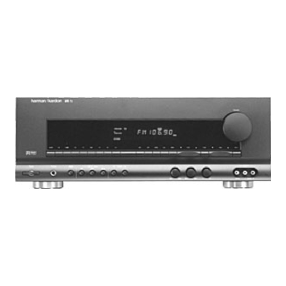
Page 6: Front Panel Controls
ˆ AVR 75 AM•FM T•MON T•2 Digital Input Power Phones Night 1 Power 2 AM/FM Tuner Mode Selector 3 Headphone Jack 4 CD 5 Tape1/ Monitor 6 Night Mode 7 Tape 2 8 TV Input 9 Digital Input Selectors ) DVD Input Front Panel Controls ı... -
Page 7: Front Panel Controls
ı Information display: This display delivers messages and status indications to help you operate the receiver. Refer to the separate diagram for complete explanation of the FL display. ˆ Remote Sensor Window: The sensor behind this window receives infrared signals from the remote con- trol. -
Page 8: Front Panel Information Display
Front Panel Information Display TV DVD V1 V2 V3 VISUAL AC-3 DIGITAL LOGIC • STEREO A AC-3 Indicator B Surround Mode Status C Digital Mode Indicators D Sleep Indicator E Night Indicator F P-Scan O N M L TEST MEMO AUTO TUNED STEREO MOVIE COAX •... -
Page 9: Front Panel Information Display
Front Panel Information Display A AC-3 Indicator: This indicator illuminates when the AVR75 is decoding a Dolby Digital input source. B Surround Mode Status: These indicators display the currently selected surround mode. C Digital Mode Indicators: These indicators show which digital input is in use. -
Page 10: Rear Panel Connections
› Front fi Switched AC Outlet fl Unswitched AC Outlet ‡ Power Cable ° AC-3/PCM Optical Input · AC-3/PCM Coaxial Input a AC-3 RF Input MODEL NO.: AVR75 HARMAN KARDON NORTHRIDGE AC-3 CALIFORNIA, U.S.A. RF IN MADE IN JAPAN CENTER AC-3/PCM... -
Page 11: Rear Panel Connections
IR sensor in the receiver to serve other remote controlled devices. Connect this jack to the “IR IN” jack on Harman Kardon or other compatible equipment. d VCR 1 Inputs: Connect these jacks to the audio, video and S-Video PLAY/OUT jacks of a VCR. -
Page 12: Remote Control Functions
M E M O M E M O AM/FM COAX PRESET DISC TAPE 1 FM MODE TAPE 2 DISPLAY SELECT AVR 75 Learning SLEEP 3 ST MOVIE MATRIX HALL D E F G H I M N O P Q R... - Page 13 Mute: Press this button to tem- porarily cut the audio output of the receiver. Press it again to return to the previous volume level. r Transport Controls: These buttons may be programmed to...
-
Page 14: Remote Control Functions
Sending LED: This indicator should flash any time a button is pressed to confirm that a command is being sent to the receiver or another unit. If the light is dim or does not illuminate when a button is pressed the batteries in the remote... -
Page 15: Installation And Setup
NOTE: When the source device has both fixed and variable audio outputs it is best to use the fixed output unless you find that the input to the receiver is so low that the sound is noisy, or high that the signal is distorted. -
Page 16: Installation And Setup
Remote Cont. jack to the Remote In jack on Harman Kardon or other compatible equipment. External Audio Power Amplifier Connections If desired, optional external power audio power amplifiers may be used with the AVR75. -
Page 17: Remote Control Programming And Operation
Remote Control Programming and Operation This product is equipped with a powerful remote control. As supplied, it will operate the receiver, as well as most CD players and tape decks manufactured by Harman Kardon. If your equipment requires differ- ent codes, it may be programmed to copy the codes from most infrared remotes. -
Page 18: Remote Control Programming And Operation
WARNING: These keys transmit codes that are vital to the operation of the product. It is not recommended that they be programmed with alternative codes, as it may then be impossible to operate certain functions of the receiver. Night Delay Coax Select All Navigation Buttons ‹... -
Page 19: System Configuration
When all audio, video and system con- nections have been made, there are a few configuration adjustments to be made. A few minutes spent to correctly configure and calibrate the unit will greatly add to your listening experience. Speaker Selection The placement of speakers in a multi- channel home theater system can have a noticeable impact on the quality of... - Page 20 2. Install the supplied AAA batteries in the remote as shown on page 15. 3. Turn on the TV connected to the receiver. Select the appropriate video input on the TV. NOTE: Although the unit will switch S-Video signals, the on-screen menus control system is NOT visible on the S-Video output.
- Page 21 9. Enter the information for the . speaker by using the SURROUND CH buttons on the remote to ‹ › select the type of surround channel speaker that will be used. Press the buttons so that LARGE SMALL is highlighted to match the speak- NONE er type you will use as described in #7 above.
-
Page 22: System Configuration
AVR75 is adjustment of the output levels. Correct adjustment of these settings is critical to proper oper- ation of the receiver in all surround modes, and particularly when Dolby Digital sources are being played. 1. To set the output levels press the... -
Page 23: Basic Operation
Once the input source, speaker and antenna connections have been made, and the system has been configured, the receiver is ready for operation. Note that some controls are duplicated on both the front panel and the remote control, while others appear on one or the other, but not both. -
Page 24: Digital Audio Sources
NOTE: Once a program has been encoded with surround information, it retains the surround matrix as long as the program is broadcast in stereo. Thus, movies with surround sound will carry surround information when they are broadcast via conventional TV stations, cable, pay TV and satellite transmission. - Page 25 When manually tuning stations, observe indicator Signal Level indicators . The more Tuned bars that are visible on the Signal indicator, the stronger the signal Level and the better the station will sound. A station is properly tuned when the indicator is illuminated.
- Page 26 1. Tune to the desired preset station. 2. Press and hold the button Memo for more than three seconds. 3. Note that a character on the left side of the main information display will start to blink. 4. Enter the first character of the name using either the front panel Tune ⁄...
-
Page 27: On-Screen Display
NOTE: In order to view the on-screen menu displays the receiver must be con- nected to the standard, composite video input of a TV monitor or projector. The on-screen displays are NOT visible via the S-Video output. - Page 28 Surround Mode and Delay When the surround mode is changed or the delay timing is adjusted, a message will appear at the bottom of the video screen (see figure #10). The top line is the surround mode, the bottom line is the delay time for that mode.
-
Page 29: On-Screen Display
. When either input AUDIO VIDEO type is highlighted in reverse video use buttons to select the ‹ › source you wish to listen to or view. Remember that the video source should be selected first when you wish to watch one source and listen to another. -
Page 30: Advanced Features
If you select another input, such as CD or the AM/FM tuner after the unit has turned on, it will remain on even if the TV is turned off. You must then turn the receiver off using the front panel or remote buttons Power NOTE: The TV Auto On Function will only respond to conventional video signals. -
Page 31: Digital Audio Playback
3. Subtract the distance to the surround speakers from the distance to the front speakers. a. When setting the delay time for the Dolby Digital surround mode, the optimal delay time is the result- ing figure. For example, if the front speakers are ten feet away and the surround speakers are five feet away, the optimal delay time is... - Page 32 if it is a multichannel Dolby Digital source or a conventional PCM signal, which is the standard output from CD players. An indicator will light in the Front Panel Information Display to confirm the digital signal is AC-3 A and if the source is PCM Q Coax C Optical...
-
Page 33: Surround Mode Chart
The first time a PCM source is played the AVR75 will automatically select the Stereo mode, but you may then select any surround mode desired. Surround Mode Chart MODE FEATURES DOLBY DIGITAL This mode is used only when the source material is encoded with Dolby Digital (AC-3) data. -
Page 34: Troubleshooting Guide
• Turn up volume control. • Check speaker wire connections at receiver and speaker ends for shorts. • Contact your local Harman Kardon service depot. • Select a mode other than Stereo or Monaural. • There is no surround information from mono sources. -
Page 35: Technical Specifications
Audio Section Stereo Mode Continuous Average Power (FTC) 70 Watts per channel 20Hz–20kHz: @ < 0.07% THD, both channels driven into 8 Ohms Five-Channel Surround Mode Power Per Individual Channel Front L&R channels: 65 Watts per channel, @ 0.07% THD, 20Hz–20kHz into 8 ohms Center channel: 65 Watts, 20Hz–20kHz into 8 ohms Surround channels:... - Page 36 AVR 75 VISUA AC-3 STERE AM•FM T•MON T•2 Digital Input Power Phones Night Coax Printed in Japan Part #1111-AVR75 294J851250...