Table of Contents
Advertisement
Quick Links
Advertisement
Table of Contents

Related Manuals for Citizen CT-E301


Summary of Contents for Citizen CT-E301
- Page 1 LINE THERMAL PRINTER MODEL CT-E301 User’s Manual...
- Page 2 WEEE MARK If you want to dispose of this product, do not mix it with general household waste. There is a separate collection systems for used electronics products in accordance with legislation under the WEEE Directive and is effective only within European Union. Wenn Sie dieses Produkt entsorgen wollen, dann tun Sie dies bitte nicht zusammen mit dem Haushaltsmüll.
- Page 3 (2011/65/EU) Full text of the EU declaration of conformity is available at the following internet address: http://www.citizen-systems.co.jp/en/printer/download/eu_doc.html IMPORTANT: This equipment generates, uses, and can radiate radio frequencye- nergy and if not installed and used in accordance with the instruction manual, maycause interference to radio communications.
- Page 4 Note that Citizen Systems is not responsible for any operation results regard- less of omissions, errors, or misprints in this manual. l Note that Citizen Systems is not responsible for any trouble caused as a result of using options or consumables that are not specified in this manual.
- Page 5 CITIZEN is a registered trademark of Citizen Watch Co., Ltd. l All other trademarks are the property of their respective owners. l Citizen Systems use these trademarks in accordance with the license of relevant owners. Copyright© CITIZEN SYSTEMS JAPAN CO., LTD. 2021...
- Page 6 SAFETY PRECAUTIONS ...WHICH SHOULD BE STRICTLY OB- SERVED Before using this product for the first time, carefully read these SAFETY PRECAU- TIONS. Improper handling may result in accidents (fire, electric shock or injury). In order to prevent injury to operators, third parties, or damage to property, special warn- ing symbols are used in the User’s Manual to indicate important items to be strictly ob- served.
- Page 7 Should it occur, immediately turn the printer off, unplug it from the sup- ply outlet, and call your local Citizen Systems dealer. n Do not handle the printer in the following ways: l Do not subject the printer to strong impacts or hard jolts (e.g., being stepped on, dropped or struck).
- Page 8 WARNING This device is not appropriate to be used where a child may be present. In- stall, store, or use the device where it cannot be reached by a child. l Electric appliances could cause an unexpected injury or accident if they are handled or used improperly.
- Page 9 CAUTION Do not use the printer under the following conditions. l Avoid locations subject to vibration or instability. l Avoid locations where the printer is not level. u The printer may fall and cause an injury. u The quality of printing may deteriorate. l Do not obstruct the printer’s air vents.
- Page 10 CAUTION n Connect the printer to a ground. l Electric leakage may cause an electric shock. n Do not connect the printer’s ground to any of the following: * Gas piping l A gas explosion could result. * Telephone line ground * Lightning rod l If lightning strikes a large surge of current may cause fire or shock.
- Page 11 Neglecting these cautions may cause wires or insulation to break, which could result in electric leakage, electric shock, or printer failure. If the power cord sustains damage, contact your Citizen Systems dealer. l Do not leave things around the electric outlet.
- Page 12 WARNING l Hold the plug and connector when plugging or unplugging the power cord or signal cable after turning off the printer and the appliance connected to it. – 12 –...
- Page 13 CAUTION Caution label is attached in the position shown in the following figure. Carefully read the handling precautions before using the printer. These labels indicate that the head becomes hot, so touching it may cause burns, and touching the auto cutter when opening the paper cover may cause cuts on hands.
- Page 14 Do not touch any of the moving parts (e.g., paper cutter, gears, active electric parts) while the printer is working. l In case of trouble do not attempt to repair the printer. Ask Citizen Systems serv- ice for repair.
- Page 15 CAUTION The thermal head is at a dangerously high temperature immediately after printing. Allow it to cool off before starting maintenance work. – 15 –...
-
Page 16: Table Of Contents
THE TABLE OF CONTENTS 1. GENERAL OUTLINE ..............17 Features ..................17 Unpacking ..................18 Model Classification ..............19 Basic Specifications ..............19 2. EXPLANATION OF PRINTER PARTS ........21 Printer Appearance ..............21 Inside the Paper Cover ..............24 Other Built-in Functions .............. -
Page 17: General Outline
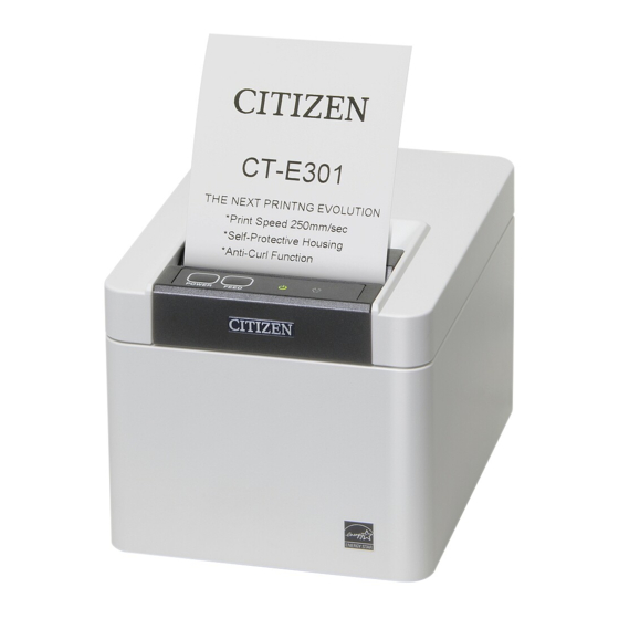
1. GENERAL OUTLINE The CT-E301 line thermal printer series is designed for use with a broad array of termi- nal equipment including data, POS, and kitchen terminals. These printers have extensive features so they can be used in a wide range of applica- tions. -
Page 18: Unpacking
1.2 Unpacking Make sure the following items are included with your printer. QUAN- NAME ILLUSTRATION TITY Printer AC Adapter (37AD5) AC power cord Quick Start Guide – 18 –... -
Page 19: Model Classification
Contact us in advance for special combinations, some of which may not be available. 1.4 Basic Specifications Item Specifications Model CT-E301 Print method Line thermal dot print method Print widths 72 mm/576 dots, 68.25 mm/546 dots, 64 mm/512 dots, 54.5 mm/436 dots, 54 mm/432 dots, 52.5 mm/420 dots, 48.75 mm/390 dots, 48 mm/384 dots, 45... - Page 20 Item Specifications Character type Alphanumeric characters, international characters, PC437/850/852/857/858/860/863/864/865/866, WPC1252, Katakana, ThaiCode 11/18 (1Pass/3Pass), TCVN-3, Kanji (JIS first, second, third, and fourth level), Ka- na, extended characters, JIS X0213, GB18030, BIG5, KS Hangul, EUC Hangul User memory 384 KB (capable of storing user-defined characters and logos) Bar code types UPC-A/E, JAN(EAN) 13 digits/8 digits, ITF, CODE39, CODE128, CODABAR (NW-7), CODE93, PDF417, QR Code, GS1-DataBar...
-
Page 21: Explanation Of Printer Parts
2. EXPLANATION OF PRINTER PARTS 2.1 Printer Appearance Names of parts 1: Paper cover Open to load paper. Also open to clear a cutter error. Refer to 4.2 Clearing a Cutter Error 2: Cover open lever Use to open the paper cover. 3: POWER button Hold down two or three seconds to switch power on or off. - Page 22 6: Rear connectors Operation panel Two LEDs and two keys are placed on the operation panel. LED name Description Turns on when the power is turned on and turns off when the power is turned off. POWER LED Flashes when a memory error occurs and when data is being re- ceived.
- Page 23 Rear connectors USB+serial+Ethernet 1: Serial connector 2: Cash drawer kick-out connector Connect to the cable from the cash drawer. 3: Power connector Connect to the AC adapter cable. 4: USB connector 5: Ethernet connector 6: Panel button The current configuration information can be printed. For details, refer to “Ethernet (LAN) Interface”...
-
Page 24: Inside The Paper Cover
2.2 Inside the Paper Cover 1: Print head (thermal) Prints characters and graphic data on paper (paper rolls). 2: Paper end (PE) sensor Detects when there is no paper. Printing stops when this sensor detects there is no paper. 3: Platen Feeds the paper. - Page 25 Notes The anti-curling roller and anti-curling damper do not straighten the paper completely. – 25 –...
-
Page 26: Other Built-In Functions
2.3 Other Built-in Functions l Buzzer Buzzes when errors occur or when operations or command operations are per- formed. Refer to 4.5 Error Indications l User memory You can save user-defined logo and character data in this memory. Data remains stored in this memory even if the printer is turned off. - Page 27 CAUTION Remove the partially cut paper before performing back feed for starting printing. The cut paper may be torn off in the next printing process, which may cause a problem. l Auto side shift (MSW8-6) This function dissipates heat load during frequent heat generation by a vertical ruled line or other specific head heating element.
-
Page 28: Setup
3. SETUP 3.1 Connecting the AC Power Cord 1. Turn off the power. 2. Connect the power connector to the AC adapter cable connector. Next, connect the AC power cord to the AC inlet, and insert the plug into an electric outlet. - Page 29 CAUTION n Use only the specified AC adapter. n Always hold the AC adapter’s cable connector by the connector when removing or inserting n Use an AC power source that does not also supply power to equipment that generates elec- tromagnetic noise.
-
Page 30: Connecting Interface Cables
3.2 Connecting Interface Cables 1. Turn off the power. 2. Orient the interface cable correctly and insert it into the interface connector. USB+serial+Ethernet CAUTION n When disconnecting the cable, always hold the connector. n Be careful not to insert the USB cable into the cash drawer kick-out connector. n Hold the connector of the LAN cable perpendicular and straight when connecting or discon- necting it. - Page 31 Notes To connect more than one printer to a single computer by USB, you must change the serial number of the USB interface. Use a serial cable with the connection layout shown below. 9-pin (female) - 9-pin (female) cable Printer Signal Pin Pin Signal CAUTION...
-
Page 32: Ethernet (Lan) Interface
3.3 Ethernet (LAN) Interface The following describes an overview of the Ethernet (LAN) interface. For details on this function, refer to a separate manual. Note that the Ethernet (LAN) interface is not available in the USB model. Panel button operation The function of the panel button is as follows. - Page 33 1: Network transmission speed Transmission speed LED (green) 100 Mbps 10 Mbps/Not connected Unlit 2: Network status Status LED (yellow) Connected Not connected Unlit Data transmission in progress Flashing Changing network settings You can use a web browser to access a special settings page to check and change board settings.
- Page 34 3. Press the [Change Settings] button to enter the following Change Settings screen. For details, refer to a separate manual. – 34 –...
-
Page 35: Connecting The Cash Drawer
3.4 Connecting the Cash Drawer 1. Turn off the power. 2. Confirm the orientation of the cash drawer kick-out cable connector and connect it to the cash drawer kick-out connector at the back of the printer. 3. Remove the screw for the ground wire. 4. - Page 36 Signal Function Frame ground DRAWER1 Cash drawer 1 drive signal DRSW Cash drawer switch input Cash drawer drive power supply DRAWER2 Cash drawer 2 drive signal Signal ground (common ground on circuits) * Connector used:TM5RJ3-66 (Hirose) or equivalent * Applicable connector: TM3P-66P (Hirose) or equivalent (2) Electric characteristics 1) Drive voltage: 24 VDC 2) Drive current: Approx.
-
Page 37: Precautions For Installing The Printer
3.5 Precautions for Installing the Printer This product can be used horizontally or wall-mounted. Cannot be used vertically. Horizontal position Vertical position Wall-mounted CAUTION n Do not use the printer under the following conditions. l Avoid locations subject to vibration or instability. l Locations that are very dirty or dusty. -
Page 38: Loading Paper
3.6 Loading Paper 1. Turn on the power. 2. Pull the cover open lever toward you to open the paper cover. – 38 –... - Page 39 3. Load the paper roll so that the printable side of the paper is facing up, as shown by arrow A. Set the roll paper so that it passes over the paper anti-curling damper. 4. Pull a few centimeters of paper straight out in the direction of arrow B. 5.
- Page 40 CAUTION n When opening the paper cover, be careful not to touch the entrance of the blade of the auto cutter. n The print head is very hot immediately after printing. Be careful not to touch it with your hands. n Do not touch the print head with bare hands or metal objects.
-
Page 41: 58-Mm Width Roll Paper Partition
3.7 58-mm Width Roll Paper Partition 1. Turn off the power. 2. Pull the cover open lever toward you to open the paper cover. 3. Mount the supplied partition to the groove. When using the 80-mm width roll paper, remove the partition. 4. -
Page 42: Precautions For Creating Applications And Practical Operations
If this is the case, try using a cable with ferrite cores on both ends, which are very effec- tive at eliminating EMI. 3.9 Download Site for Various Electronic Files You can view support information and download the latest documents, drivers, utilities, etc. from the following site. https://www.citizen-systems.co.jp/en/printer/download/#CT-E301 – 42 –... -
Page 43: Maintenance And Troubleshooting
4. MAINTENANCE AND TROUBLE- SHOOTING 4.1 Periodic Cleaning How to care for the printer’s exterior surface After turning off the printer, wear gloves and use a soft cloth or an absorbent cotton to wipe it off. At this time, be sure to unplug the AC power cord from the outlet. CAUTION n Prolonged use of cleaning agents may cause whitening of the outer case. - Page 44 1. Print head 2. Platen CAUTION n When opening the paper cover, be careful not to touch the entrance of the blade of the auto cutter. n The print head is very hot immediately after printing. Be careful not to touch it with your hands.
-
Page 45: Clearing A Cutter Error
4.2 Clearing a Cutter Error If the auto cutter stops during the auto cutter operation with the blade of the auto cutter in the open position due to foreign matter entering, paper jamming, etc., the ERROR LED flashes. When a cutter error occurs, resolve the cutter error with the following procedure. 1. -
Page 46: Self Test
4.3 Self Test You can use self test to check for printer problems. Performing a self test operation 1. While paper is loaded, press and hold the FEED button and turn on the power. 2. Hold the FEED button down for about one second until the buzzer sounds. Release the button to start self test. -
Page 47: Hexadecimal Dump Printing
4.4 Hexadecimal Dump Printing Print received data in hexadecimal. If problems such as missing or duplicated data oc- cur, this function allows you to check whether or not the printer is receiving data correct- How to do hexadecimal dump printing 1. -
Page 48: Error Indications
4.5 Error Indications l Paper End If the paper ends, the ERROR LED lights and a buzzer sounds. Load a new paper roll. The buzzer may not sound depending on the memory switch setting. l Cover Open If the cover is opened, the ERROR LED lights. The buzzer may also sound depending on the memory switch setting. - Page 49 Status POWER LED (green) ERROR LED (red) Buzzer sound *3 Data reception Unlit Notes *1 Indicated when a cover is opened during standby. *2 Indicated when a cover is opened during printing. *3 The buzzer sounds when MSW5-1 (buzzer setting) is enabled. However, the condition that the buzzer sounds varies depending on the MSW5-1 and MSW10-5 settings.
-
Page 50: Paper Jams
4.6 Paper Jams Take care to avoid obstruction of the paper outlet and paper jamming around the outlet during printing. If paper cannot get out of the printer, it can roll up on the platen inside the printer and cause an error. If the paper wraps around the platen, open the paper cover and carefully pull the paper out. -
Page 51: Other
5. OTHER 5.1 External Views and Dimensions (Unit: mm) – 51 –... -
Page 52: Printing Paper
5.2 Printing Paper Use the paper shown in the following table or paper of the same quality. Paper type Product name Recommended Nippon Paper TP50KR-2Y, TP50KJ-R, TL69KS-LH, TF50KS-E2D thermal roll paper Oji Paper PD150R, PD160R, PD160R-63 Mitsubishi Paper Mills HP220AB-1, P220AB Koehler KT48-FA (Unit: mm) Paper width 80... - Page 53 Notes Use thermal paper that is wound as follows: l Not creased and fits tight to the core. l Not folded. l Not glued to the core. l Rolled with the printable side out. – 53 –...
-
Page 54: Manual Setting Of Memory Switches
3. Press the FEED button three and close the paper cover. The printer enters memory switch quick setting mode. The selectable item “Model” and the selection are printed. Model ( CITIZEN CT-S310 ) Selection Selectable item 4. Press the FEED button. - Page 55 MSW3-7 MSW6-2 Paper Character MSW8-1 Manufacturer Full Col CBM1000 Character width space Print Width Print Mode Space CITIZEN 58 mm WaitData Invalid 384 dots 80 mm WaitData Invalid 576 dots CT-S310 0 dot WaitData Invalid 360 dots 0 dot 58 mm...
- Page 56 5. Press the FEED button for at least two seconds. A setting for the memory switch is printed, through the cycle, each time the FEED button is pressed for at least two seconds. Press the FEED button for at least two seconds to cycle through the list until the function of the memory switch you want to change is printed.
- Page 57 4. Press the FEED button for at least two seconds. All memory switches change to the factory settings. 5. Close the paper cover. The function of each memory switch is shown in the following table. (Shaded values are factory settings.) Switch no.
- Page 58 Switch no. Function MSW5-8 Reserved Fixed — MSW6-1 Act. For Driver Invalid Valid MSW6-2 Character Space Invalid Valid MSW6-3 USB Power Save Invalid Valid MSW6-4 Reserved Fixed — MSW6-5 Reserved Fixed — MSW6-6 Reserved Fixed — MSW6-7 Reserved Fixed — MSW6-8 Power ON trigger Power switch ON...
- Page 59 CT-E301_UM_110_EN PMC-2207 July 2022...