Table of Contents
Advertisement
Quick Links
Advertisement
Table of Contents

Related Manuals for Citizen CT-E601


Summary of Contents for Citizen CT-E601
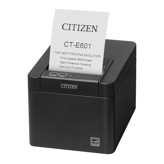
- Page 1 LINE THERMAL PRINTER MODEL CT-E601 User’s Manual...
- Page 2 WEEE MARK If you want to dispose of this product, do not mix it with general household waste. There is a separate collection systems for used electronics products in accordance with legislation under the WEEE Directive and is effective only within European Union. Wenn Sie dieses Produkt entsorgen wollen, dann tun Sie dies bitte nicht zusammen mit dem Haushaltsmüll.
- Page 3 (2011/65/EU) Full text of the EU declaration of conformity is available at the following internet address: http://www.citizen-systems.co.jp/en/printer/download/eu_doc.html IMPORTANT: This equipment generates, uses, and can radiate radio frequencye- nergy and if not installed and used in accordance with the instruction manual, maycause interference to radio communications.
- Page 4 Note that Citizen Systems is not responsible for any operation results regard- less of omissions, errors, or misprints in this manual. l Note that Citizen Systems is not responsible for any trouble caused as a result of using options or consumables that are not specified in this manual.
- Page 5 CITIZEN is a registered trademark of Citizen Watch Co., Ltd. l All other trademarks are the property of their respective owners. l Citizen Systems use these trademarks in accordance with the license of relevant owners. Copyright© CITIZEN SYSTEMS JAPAN CO., LTD. 2021...
- Page 6 SAFETY PRECAUTIONS ...WHICH SHOULD BE STRICTLY OB- SERVED Before using this product for the first time, carefully read these SAFETY PRECAU- TIONS. Improper handling may result in accidents (fire, electric shock or injury). In order to prevent injury to operators, third parties, or damage to property, special warn- ing symbols are used in the User’s Manual to indicate important items to be strictly ob- served.
- Page 7 Should it occur, immediately turn the printer off, unplug it from the sup- ply outlet, and call your local Citizen Systems dealer. n Do not handle the printer in the following ways: l Do not subject the printer to strong impacts or hard jolts (e.g., being stepped on, dropped or struck).
- Page 8 WARNING This device is not appropriate to be used where a child may be present. In- stall, store, or use the device where it cannot be reached by a child. l Electric appliances could cause an unexpected injury or accident if they are handled or used improperly.
- Page 9 CAUTION Do not use the printer under the following conditions. l Avoid locations subject to vibration or instability. l Avoid locations where the printer is not level. u The printer may fall and cause an injury. u The quality of printing may deteriorate. l Do not obstruct the printer’s air vents.
- Page 10 CAUTION n Connect the printer to a ground. l Electric leakage may cause an electric shock. n Do not connect the printer’s ground to any of the following: * Gas piping l A gas explosion could result. * Telephone line ground * Lightning rod l If lightning strikes a large surge of current may cause fire or shock.
- Page 11 Neglecting these cautions may cause wires or insulation to break, which could result in electric leakage, electric shock, or printer failure. If the power cord sustains damage, contact your Citizen Systems dealer. l Do not leave things around the electric outlet.
- Page 12 WARNING l Hold the plug and connector when plugging or unplugging the power cord or signal cable after turning off the printer and the appliance connected to it. – 12 –...
- Page 13 CAUTION Caution label is attached in the position shown in the following figure. Carefully read the handling precautions before using the printer. These labels indicate that the head becomes hot, so touching it may cause burns, and touching the auto cutter when opening the paper cover may cause cuts on hands.
- Page 14 Do not touch any of the moving parts (e.g., paper cutter, gears, active electric parts) while the printer is working. l In case of trouble do not attempt to repair the printer. Ask Citizen Systems serv- ice for repair.
- Page 15 CAUTION The thermal head is at a dangerously high temperature immediately after printing. Allow it to cool off before starting maintenance work. – 15 –...
-
Page 16: Table Of Contents
THE TABLE OF CONTENTS 1. GENERAL OUTLINE ..............18 Features ..................18 Unpacking ..................20 Model Classification ..............21 Basic Specifications ..............21 2. EXPLANATION OF PRINTER PARTS ........24 Printer Appearance ..............24 Inside the Paper Cover ..............27 Other Built-in Functions .............. - Page 17 Paper Jams .................. 78 Precautions for Performing Printing for Which Printing Speed Changes ..................78 5. OTHER ..................79 External Views and Dimensions ........... 79 Printing Paper ................80 Manual Setting of Memory Switches ..........82 – 17 –...
-
Page 18: General Outline
1. GENERAL OUTLINE The CT-E601 line thermal printer series is designed for use with a broad array of termi- nal equipment including data, POS, and kitchen terminals. These printers have extensive features so they can be used in a wide range of applica- tions. - Page 19 l User created characters and logos can be saved in the user memory l Support for barcodes including 2D barcodes l Apple MFi certified Bluetooth and USB (Lightning) communication support (Blue- tooth model, Lightning model) – 19 –...
-
Page 20: Unpacking
1.2 Unpacking Make sure the following items are included with your printer. QUAN- NAME ILLUSTRATION TITY Printer AC Adapter (37AD5) AC power cord Quick Start Guide – 20 –... -
Page 21: Model Classification
Contact us in advance for special combinations, some of which may not be available. 1.4 Basic Specifications Item Specifications Model CT-E601 Print method Line thermal dot print method Print widths 72 mm/576 dots, 68.25 mm/546 dots, 64 mm/512 dots, 52.5 mm/420 dots, 48.75... - Page 22 Item Specifications Number of print columns Font Maximum number Maximum number Dot configuration of characters (col- of characters (col- (dots) umns) / 80 mm umns) / 58 mm Font A 12 × 24 Font B 9 × 24 Font C 8 ×...
- Page 23 The numbers of columns noted in this table refer to typical models. The number of columns varies depend- ing on specifications. *2 Characters appear small because the dimensions include a blank area surrounding each character. *3 This standard applies when our AC Adapter (37AD5) is used. –...
-
Page 24: Explanation Of Printer Parts
2. EXPLANATION OF PRINTER PARTS 2.1 Printer Appearance Names of parts 1: Paper cover Open to load paper. Also open to clear a cutter error. Refer to 4.2 Clearing a Cutter Error 2: Cover open lever Use to open the paper cover. 3: POWER button Hold down two or three seconds to switch power on or off. - Page 25 Operation panel The operation panel has five LEDs and two buttons. LED name Color Description Lights when the power is on, turns off when the power POWER LED Green is off. Lights or flashes when no paper or low paper is de- tected.
- Page 26 Rear connectors (serial interface example) 1: Interface connector (serial, USB, etc.) Connect to the interface cable. 2: Cash drawer kick-out connector Connect to the cable from the cash drawer. 3: Power connector Connect to the AC adapter cable. 4: USB connector 5: USB power supply port Supply power to a USB device.
-
Page 27: Inside The Paper Cover
2.2 Inside the Paper Cover 2, 3 1: Print head (thermal) Prints characters and graphic data on paper (paper rolls). 2: Paper near-end (PNE) sensor Detects when the paper is near the end of the roll. Adjust the position of the sensor to determine when it detects the end of the paper is near. - Page 28 8: Paper anti-curling roller Roller for reducing the warp of the paper. 9: Paper anti-curling damper Damper for reducing the warp of the paper. 10: Paper jamming sensor Sensor for detecting paper jam and stopping the printing. Notes The anti-curling roller and anti-curling damper do not straighten the paper completely. –...
-
Page 29: Other Built-In Functions
2.3 Other Built-in Functions l Buzzer Buzzes when errors occur or when operations or command operations are per- formed. Refer to 4.6 Error Indications l User memory You can save user-defined logo and character data in this memory. Data remains stored in this memory even if the printer is turned off. - Page 30 CAUTION Remove the partially cut paper before performing back feed for starting printing. The cut paper may be torn off in the next printing process, which may cause a problem. l Auto side shift (MSW8-6) This function dissipates heat load during frequent heat generation by a vertical ruled line or other specific head heating element.
-
Page 31: Setup
3. SETUP 3.1 Connecting the AC Power Cord 1. Turn off the power. 2. Connect the power connector to the AC adapter cable connector. Next, connect the AC power cord to the AC inlet, and insert the plug into an electric outlet. -
Page 32: Serial Interface Board
3.2 Serial Interface Board Data can be exchanged by serial communication. Connecting the Interface Cable 1. Turn off the power. 2. Confirm the orientation of the interface cable and connect it to the port. 3. Insert the other connector firmly into the interface port of the host computer. CAUTION n When disconnecting the cable, always hold the connector. - Page 33 9-pin (female) - 9-pin (female) cable Printer Signal Pin Pin Signal – 33 –...
-
Page 34: Usb Interface
3.3 USB Interface Data can be exchanged by USB communication. Specifications Standard USB 2.0 specification-compliant Communication speed Supports 12 Mbps (Full-Speed) transfer Connecting the Interface Cable 1. Turn off the power. 2. Confirm the orientation of the interface cable and connect it to the port. 3. -
Page 35: Bluetooth Interface Board
3.4 Bluetooth Interface Board Names of parts 1. Status LED The Bluetooth communication/connection/error status is indicated by this LED. 2. USB connector Data can be exchanged by USB communication. Notes When using this interface board as a USB interface, do not connect USB cables to both the main unit side and interface board side. - Page 36 Pairing operation You need to perform the operations below the first time you establish a Bluetooth con- nection for Bluetooth data communication. 1. Detect Bluetooth devices 2. Configure pairing settings 1: Detecting Bluetooth devices Confirm that Bluetooth is enabled on the host PC before searching for Bluetooth devices.
- Page 37 To delete printer pairing information, open the paper cover and then hold down the FEED button for five seconds. Deleting pairing information on the printer will put the printer into discovery mode. Auto reconnection With iOS device Bluetooth communication, a connection between a paired iOS device and the printer is not automatically restored after it is lost.
-
Page 38: Bluetooth Usb Host Interface Board
3.5 Bluetooth USB host interface board In addition to printer control via Bluetooth communication, Bluetooth USB host interfa- ces can control peripheral devices connected via a USB port. Connecting a Peripheral Device 1. Turn off the power. 2. Connect the cable of a peripheral device to this port. Notes A peripheral device cannot be controlled if it is connected to the USB power supply port. - Page 39 Connecting a USB Device The function assigned to each USB port differs. Connect the USB device to be connected to the correct place in reference to the follow- ing figure. 1: For peripheral device control Connect a peripheral device. The connected peripheral device can be controlled. 2: For host computer communication Connect with a host computer.
- Page 40 Names of parts 1: Panel button Control this interface board. 2: USB 2 port Connect a peripheral device. Notes n Only connect peripheral devices specified by our company to the USB port. n Only plug in/remove peripheral devices when the printer power is turned off. Pairing operation You need to perform the operations below the first time you establish a Bluetooth con- nection for Bluetooth data communication.
- Page 41 2: Configuring pairing settings Normally, selecting the printer during device detection will transition directly to pair- ing settings. Notes Some host PC configurations and models may not transition directly to pairing settings after the printer is selected during device detection. The operation required to configure pairing settings depends on whether SSP (secure simple pairing) is enabled on the host PC.
- Page 42 Notes n This function is enabled when shipped from the factory. (MSW13-6) Auto reconnection can take some time to connect when the host is not an iOS de- vice. n Even if the partner device is an iOS device, the conditions below can interfere with the auto reconnection function.
- Page 43 Enabling and disabling auto reconnect During self test, press the FEED button 3 times -> Auto reconnect = Valid During self test, press the FEED button 4 times -> Auto reconnect = Invalid At the end of self test, new setting will be printed as Auto reconnect [Valid] or [Invalid]. Refer to 4.4 Self Test –...
- Page 44 Panel button operation Use the panel button on the rear of the Bluetooth board to operate this board. Panel button USB port l BT device search (MSW13-5) settings 1. Press and hold the panel button to turn on printer power. 2.
- Page 45 Print example 1. Board firmware version 2. Address of equipped Bluetooth module 3. Bluetooth name 4. Response profile in Bluetooth transmission 5. Bluetooth setting state 6. Name of connected USB device (“No connection” is displayed when there is no connection) 7.
-
Page 46: Ethernet (Lan)/Wireless Lan Interface Board
3.6 Ethernet (LAN)/Wireless LAN Interface Board This section provides an overview of the interface board. For details on this board, in- cluding explanations about the USB host function and XML peripheral device support, refer to the separate manual. Connecting the Interface Cable 1. - Page 47 Connecting a Peripheral Device 1. Turn off the power. 2. Connect the cable of a peripheral device to this port. Notes A peripheral device cannot be controlled if it is connected to the USB power supply port. Be sure to connect it to the USB port of the interface board. Connecting the wireless LAN adapter 1.
- Page 48 Connecting a USB Device The function assigned to each USB port differs. Connect the USB device to be connected to the correct place in reference to the follow- ing figure. Ethernet/Wireless LAN Wireless LAN USB host model 1: For peripheral device control and wireless LAN adapter connection Connects the peripheral devices and wireless LAN adapter.
- Page 49 Panel button operation Board operations are performed using the panel button on the rear of the LAN board. Panel button Panel button Panel button Ethernet Wireless LAN Ethernet/Wireless LAN USB host model l Enabling LAN connection Turn on the printer. Operation of this board will start about 20 seconds later. l Printing LAN setup information Press the panel button.
- Page 50 LED Functions The tables below explain how to interpret LED indications. Ethernet Wireless LAN Ethernet/Wireless LAN USB host model 1: Wired LAN transmission speed Transmission speed LED (green) 100 Mbps 10 Mbps/Not connected Unlit 2: Wired LAN connection/transmission status Connection status LED (yellow) Connected Not connected...
- Page 51 Web Manager The interface board has a Web Manager function that can be used to connect to the board with a web browser and change board settings. Starting up Web Manager 1. Start up a web browser. 2. In the address field, input the board's IP address and then press [Enter]. HOME Screen This is the Web manager home screen.
- Page 52 CONFIG Screen This will display the Login dialog box shown below. Log in as an administrator and then configure interface board settings. l User Name Input a board administrator user name. (Initial setting: admin) l Password Input the administrator user password. (Initial setting: admin) l [Login] button After inputting an administrator user name and password, click the [Login] button.
-
Page 53: Lightning Usb Host Interface Board
3.7 Lightning USB host interface board In addition to printer control via USB (Lightning) communication, Lightning USB host in- terfaces can control peripheral devices connected via a USB port. For Apple products with a USB Type-C connector, such as the iPad Pro, it is possible to use the same function by using USB Type-A - Type-C cable. - Page 54 Connecting a Peripheral Device 1. Turn off the power. 2. Connect the cable of a peripheral device to this port. Notes A peripheral device cannot be controlled if it is connected to the USB power supply port. Be sure to connect it to the USB port of the interface board. –...
- Page 55 Connecting a USB Device 1: For peripheral device control Connect a peripheral device. The connected peripheral device can be controlled. 2: For Apple device connection Connect with an Apple device. The printer and Apple device will communicate via the Lightning cable. Fast charging of the Apple device can also be carried out.
- Page 56 Names of parts 1: Panel button Control this interface board. 2: USB port for peripheral device connection (3 ports) Connect a peripheral device. 3: USB port for Apple device connection (1 port) Connect an Apple device. Data can be transmitted even during fast charging of Apple devices. 4: Green LED This LED indicates the communication status with the printer.
- Page 57 Panel button operation Use the panel button on the rear of the Lightning board to operate this board. 1: Print the interface board state After starting the printer, pressing the panel button once prints the interface board state. 1. System information of this interface board 2.
- Page 58 LED Functions The tables below explain how to interpret LED indications. 1: Communication status with the printer Communicating LED (green) Not connected Unlit Connected Communication in progress Flashing 2: Connection status with an Apple device Communicating LED (red) Not connected Unlit Connected Communication failed...
-
Page 59: Usb Power Supply Port
3.8 USB Power Supply Port Power (max. 2.1 A) can be supplied to a mobile device or other USB device by connect- ing the cable of the USB device to the power supply port. Connecting Mobile Device or Other Device 1. - Page 60 Connecting a USB Device The function assigned to each USB port differs. Connect the USB device to be connected to the correct place in reference to the follow- ing figure. 1: For peripheral device control Connect a peripheral device. The connected peripheral device can be controlled. 2: For host computer communication Connect with a host computer.
-
Page 61: Connecting The Cash Drawer
3.9 Connecting the Cash Drawer 1. Turn off the power. 2. Confirm the orientation of the cash drawer kick-out cable connector and connect it to the cash drawer kick-out connector at the back of the printer. 3. Remove the screw for the ground wire. 4. - Page 62 Signal Function Frame ground DRAWER1 Cash drawer 1 drive signal DRSW Cash drawer switch input Cash drawer drive power supply DRAWER2 Cash drawer 2 drive signal Signal ground (common ground on circuits) * Applicable connector: RJ-11 (2) Electric characteristics 1) Drive voltage: 24 VDC 2) Drive current: Approx.
-
Page 63: Precautions For Installing The Printer
3.10 Precautions for Installing the Printer This product can be used horizontally or wall-mounted. Cannot be used vertically. Horizontal position Vertical position Wall-mounted CAUTION Do not use the printer under the following conditions. l Avoid locations subject to vibration or instability. l Locations that are very dirty or dusty. -
Page 64: Adjusting The Paper Near-End Sensor
3.11 Adjusting the Paper Near-end Sensor Change the settings of the paper near-end sensor to set the position at which the near- end of the paper is detected. 1. Gently press the paper near-end sensor with your finger. 2. Keep the paper near-end sensor pressed as you move it left and right. The sensor po- sitions are shown below for the various diameters of the paper roll used. -
Page 65: Loading Paper
3.12 Loading Paper 1. Turn on the power. 2. Pull the cover open lever toward you to open the paper cover. – 65 –... - Page 66 3. Load the paper roll so that the printable side of the paper is facing up, as shown by arrow A. Set the roll paper so that it passes over the paper anti-curling damper. 4. Pull a few centimeters of paper straight out in the direction of arrow B. 5.
- Page 67 CAUTION n When opening the paper cover, be careful not to touch the entrance of the blade of the auto cutter. n The print head is very hot immediately after printing. Be careful not to touch it with your hands. n Do not touch the print head with bare hands or metal objects.
-
Page 68: 58-Mm Width Roll Paper Partition
3.13 58-mm Width Roll Paper Partition 1. Turn off the power. 2. Pull the cover open lever toward you to open the paper cover. 3. Mount the supplied partition to the groove. When using the 80-mm width roll paper, remove the partition. 4. -
Page 69: Mounting The Cable Cover
3.14 Mounting the Cable Cover l Align the claws of the cable cover with the grooves in the printer main unit and then in- sert them. 1. Cable cover – 69 –... -
Page 70: Precautions For Creating Applications And Practical Operations
If this is the case, try using a cable with ferrite cores on both ends, which are very effec- tive at eliminating EMI. 3.16 Download Site for Various Electronic Files You can view support information and download the latest documents, drivers, utilities, etc. from the following site. https://www.citizen-systems.co.jp/en/printer/download/ – 70 –... -
Page 71: Maintenance And Troubleshooting
4. MAINTENANCE AND TROUBLE- SHOOTING 4.1 Periodic Cleaning How to care for the printer’s exterior surface After turning off the printer, wear gloves and use a soft cloth or an absorbent cotton to wipe it off. At this time, be sure to unplug the AC power cord from the outlet. CAUTION n Prolonged use of cleaning agents may cause whitening of the outer case. - Page 72 1. Print head 2. Platen CAUTION n When opening the paper cover, be careful not to touch the entrance of the blade of the auto cutter. n The print head is very hot immediately after printing. Be careful not to touch it with your hands.
-
Page 73: Clearing A Cutter Error
4.2 Clearing a Cutter Error If the auto cutter stops during the auto cutter operation with the blade of the auto cutter in the open position due to foreign matter entering, paper jamming, etc., the CUTTER LED flashes. When a cutter error occurs, resolve the cutter error with the fol- lowing procedure. -
Page 74: Self Test
4.4 Self Test You can use self test to check for printer problems. Performing a self test operation 1. While paper is loaded, press and hold the FEED button and turn on the power. 2. Hold the FEED button down for about one second until the buzzer sounds. Release the button to start self test. -
Page 75: Hexadecimal Dump Printing
4.5 Hexadecimal Dump Printing Print received data in hexadecimal. If problems such as missing or duplicated data oc- cur, this function allows you to check whether or not the printer is receiving data correct- How to do hexadecimal dump printing 1. -
Page 76: Error Indications
4.6 Error Indications l Paper end, paper near-end The end of the roll of paper is detected at two stages, paper near-end and paperend. When paper near-end is detected, the PAPER LED flashes. Prepare a new paper roll. When paper end is detected, the PAPER LED lights and the buzzer sounds. Load a new paper roll. - Page 77 Status POWER LED PAPER LED CUTTER COVER LED SERVICE Buz- zer*1 Paper-end Unlit Unlit Unlit Yes*2 Cover open*3 Unlit Unlit Unlit Yes*2 Cover open Unlit Unlit Unlit Yes*2 II*4 Cutter locked Unlit Unlit Unlit Print stop due Unlit Unlit Unlit to paper jam Low-voltage Unlit...
-
Page 78: Paper Jams
4.7 Paper Jams Take care to avoid obstruction of the paper outlet and paper jamming around the outlet during printing. If paper cannot get out of the printer, it can roll up on the platen inside the printer and cause an error. If the paper wraps around the platen, open the paper cover and carefully pull the paper out. -
Page 79: Other
5. OTHER 5.1 External Views and Dimensions (Unit: mm) – 79 –... -
Page 80: Printing Paper
5.2 Printing Paper Use the paper shown in the following table or paper of the same quality. Paper type Product name Recommended Nippon Paper TP50KR-2Y, TP50KJ-R, TL69KS-LH, TF50KS-E2D thermal roll paper Oji Paper PD150R, PD160R, PD160R-63 Mitsubishi Paper Mills HP220AB-1, P220AB Koehler KT48-FA (Unit: mm) (Unit: mm) - Page 81 Notes Use thermal paper that is wound as follows: l Not creased and fits tight to the core. l Not folded. l Not glued to the core. l Rolled with the printable side out. – 81 –...
-
Page 82: Manual Setting Of Memory Switches
3. Press the FEED button three and close the paper cover. The printer enters memory switch quick setting mode. The selectable item “Model” and the selection are printed. Model ( CITIZEN CT-S310 ) Selection Selectable item 4. Press the FEED button. - Page 83 MSW3-7 MSW6-2 Paper Character MSW8-1 Manufacturer Full Col CBM1000 Character width space Print Width Print Mode Space CITIZEN 58 mm WaitData Invalid 384 dots 80 mm WaitData Invalid 576 dots CT-S310 0 dot WaitData Invalid 360 dots 0 dot 58 mm...
- Page 84 Individual setting mode Set the memory switches individually. Do the settings while confirming the memory switch function and settings on the print- out. 1. Load paper. 2. While the paper cover is open, press and hold the FEED button and turn on the power. 3.
- Page 85 6. Press the FEED button. A setting is printed each time the FEED button is pressed in order through the cycle. When the current settings are printed, the COVER LED lights. Press the FEED button until the setting you want is printed. 7.
- Page 86 Switch no. Function MSW1-6 Reserved Fixed — MSW1-7 DSR Signal Invalid Valid MSW1-8 INIT Signal Invalid Valid MSW2-1 Reserved — Fixed MSW2-2 Auto Cutter Invalid Valid MSW2-3 Spool Print Invalid Valid MSW2-4 Full Col Print LineFeed WaitData MSW2-5 Resume aft PE Next MSW2-6 Reserved...
- Page 87 Switch no. Function Initial set- Setting value ting MSW7-1 Baud Rate 9600 bps 1200 bps, 2400 bps, 4800 bps, 9600 bps, 19200 bps, 38400 bps, 57600 bps, 115200 bps MSW7-2 Data Length 8bits 7bits, 8bits MSW7-3 Stop Bit 1bit 1bit, 2bits MSW7-4 Parity NONE...
- Page 88 CT-E601_UM_100_EN PMC-2103 March 2021...