Bowflex TC1000 Assembly Manual
Treadclimber 4 piece assembly
Hide thumbs
Also See for TC1000:
- Assembly and owner's manual (69 pages) ,
- Service manual (15 pages) ,
- Manual (8 pages)
Advertisement
Quick Links
Advertisement

Related Manuals for Bowflex TC1000


Summary of Contents for Bowflex TC1000
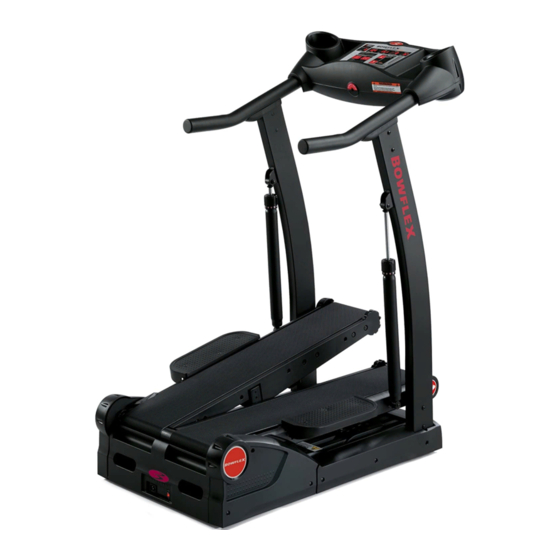
- Page 1 BOWFLEX TREADCLIMBER TC1000-TC3000-TC5000 ASSEMBLY MANUAL (4 PIECE ASSEMBLY)
- Page 2 USE THIS ASSEMBLY MANUAL WHEN IT SHIPS IN 4 PIECES (PARTLY DISASSEMBLED) - LIKE THIS DIAGRAM 1 Console assembly 2-3 Uprights 4 Base...
- Page 3 I N S T A L L I N G S T E P S Step 6: INSTALLING THE UPRIGHTS Locate the following for this step: PARTS: TreadClimber® Base & Treadle Assembly from Step 5. Figure 6-1 One (1) Left Upright Support & Hydraulic Cylinder One (1) Right Upright Support &...
- Page 4 I N S T A L L I N G S T E P S Step 8: INSTALLING THE CONSOLE/ HANDLEBAR ASSEMBLY Locate the following for this step: PARTS: TreadClimber® Base & Treadle Assembly from Figure 8-1 Step 7. Console/Handlebar Assembly HARDWARE: Six (6) 5/16”...
- Page 5 I N S T A L L I N G S T E P S Step 9: SECURING THE CONSOLE/ HANDLEBAR ASSEMBLY Locate the following for this step: Figure 9-1 PARTS: TreadClimber® Base & Treadle Assembly from Step 8. HARDWARE: Six (6) 5/16”...
- Page 6 I N S T A L L I N G S T E P S Step 10: ATTACHING THE HYDRAULIC CYLINDERS Locate the following for this step: Figure 10-1 PARTS: TreadClimber® Base & Treadle Assembly from Step 9. HARDWARE: Two (2) 5/16” x 1-1/2” Button Head Screws Two (2) 5/16”...