Table of Contents
Advertisement
Quick Links
Advertisement
Table of Contents

Related Manuals for JUKI PS-900-13090


Summary of Contents for JUKI PS-900-13090
- Page 1 PS-900-13090 INSTRUCTION MANUAL...
-
Page 2: Table Of Contents
CONTENTS 1. SPECIFICATIONS .....................1 2. CONFIGURATION .....................3 3. INSTALLATION ....................4 3-1. Setting up the sewing machine ..................4 3-1-1. Unpacking ......................4 3-1-2. Setting up the X-feed mechanism ..............6 3-1-3. Installation position of the thread stand ............8 3-1-4. Changing the position of the thread stand to the front side of the sewing machine .................... - Page 3 4-13. Adjusting the amount of oil in the hook ..............43 4-14. Adjusting the needle hole in the throat plate and the needle ........44 4-15. Adjusting the disk presser pressure ................45 4-16. Adjusting the thread end position at the beginning of sewing ........ 46 4-17.
-
Page 4: Specifications
10821- C.6.2 -ISO 11204 GR2 at 2,800 sti/min. 27 Lubricating oil #10 (Equivalent to JUKI NEW DEFRIX OIL No. 1) #32 (Equivalent to JUKI NEW DEFRIX OIL No. 2), Lithium based grease No. 2 Grease information Manufacturer: WERATCHE Type and number: Lithium base 2# grease... - Page 5 Maximum number of revolutions for sewing : 3,000 sti/min Number of revolutions for sewing at shipment : 2,800 sti/min Maximum applicable number of revolutions for sewing at each pitch Pitch Number of Revolu- Pitch Number of Revolu- Number tions tions of revolu- 0.5 ~...
-
Page 6: Configuration
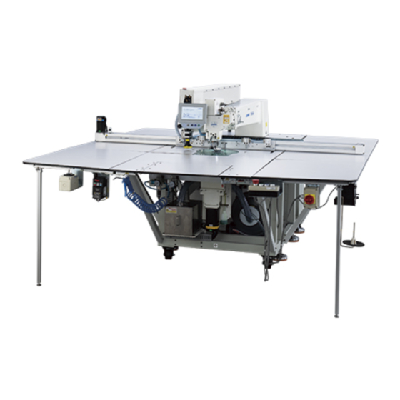
2. CONFIGURATION ❶ ❶ ❸ ❸ ❻ ❻ ❹ ❹ ❷ ❷ ❺ ❺ ❼ ❼ ❾ ❾ ❽ ❽ ❶ Machine head ❷ Table ❸ X-axis feed mechanism ❹ Y-axis feed mechanism ❺ Cassette clamp device ❻ Operation panel ❼... -
Page 7: Installation
3. INSTALLATION 3-1. Setting up the sewing machine 3-1-1. Unpacking ❶ ❶ Lift clamp ❶ as shown in the picture. If the clamp is not lifted up sufficiently, unpacking will not be smoothly carried out. ❷ ❷ Detach top cover ❷ first. Then, detach the remaining covers from the four surfaces. Remove the plastic cover. - Page 8 ❸ ❸ ❸ ❸ Remove front and rear sheet metal fittings ❸ for fixing the sewing machine. * Tools are packed in the accessory box for the sewing machine. Remove parts, accessories and feed mechanism from the wooden crate. Lift the sewing machine with a forklift to bring it to the specified location.
-
Page 9: Setting Up The X-Feed Mechanism
Turning casters ❹ , check to make sure that the sewing machine is put horizontal- ly on the forks of the forklift. Keep the sewing machine on the forks in such a way that it does not rattle. ❹ ❹ 3-1-2. - Page 10 Lay the X-feed mechanism aside the main body of the sewing machine. Move the clamp to the center of the X-feed mechanism. Detach rubber plug ❷ . Remove four nuts ❸ on the opposite side with a wrench key. Take care no to allow the screws to slip off the mounting holes after you have removed the nuts.
-
Page 11: Installation Position Of The Thread Stand
Connect the cable guide to the X feed mechanism. Then, tighten the screws. 3-1-3. Installation position of the thread stand You can select one of two installation positions Installing the thread stand to the machine head for the thread stand. at the front side of the sewing machine Installing the thread stand to the the table at the See below for how to change the installation... -
Page 12: Changing The Position Of The Thread Stand To The Front Side Of The Sewing Machine
3-1-4. Changing the position of the thread stand to the front side of the sewing machine Remove the thread stand (asm.). Remove the sheet metal, as shown in the figure, and attach the thread stand (asm.) to the sheet metal. Sheet metal Lastly, attach the relevant parts to the sewing machine. -
Page 13: Setting Up The Table
3-1-5. Setting up the table Fig.1 Set up the left, right and front (center) tables. Tighten the screws as illustrated in Fig. 1. After you have set up the right and left X feed mechanism sub tables, check to make sure that there is a clearance between the tables and the X-feed mechanism. -
Page 14: Setting Up The Switches, Bobbin Thread Winder And Switch Button (Asm.)
❶ ❶ Set up the front tables (left) and (right). Secure the aforementioned parts with dedicated link plates ❶ and the nuts. 3-1-6. Setting up the switches, bobbin thread winder and switch button (asm.) Tools are packed in the accessory box for the sewing machine. -
Page 15: Points To Be Checked And Precautions To Be Taken Before Turning The Power On
Secure the power switch plate to the alu- minum plate of the front table (right) with T-head screw A and nut B. For switch button (asm.) C, change round the direction of assembly. Then, secure it to the aluminum plate of the front table (right) with T-head screw A and nut B. - Page 16 Inspect whether the electrical components and pneumatic components are correctly assembled. Inspect whether the needle entry point is cor- rectly aligned with the center of the needle hole in the throat plate of the sewing machine. Inspect whether the X-feed mech- anism operates smoothly.
-
Page 17: Installing The Air Hose
3-1-8. Installing the air hose WARNING : Check to be sure that the air hose is fully inserted into the air cock before supplying the air to the machine so as to prevent the air from being blown directly to the human body. Then, carefully open the air cock. -
Page 18: Cautions For The Compressed Air Supply (Source Of Supply Air) Facility
When the supply air contains a considerable amount of carbon Mist separator and dust (Most troubles in the air solenoid valves are caused by carbon.) Be sure to install a mist separator. Standard equipment supplied by JUKI Filter regulator Air solenoid valve Air cylinder Cautions for main piping •... -
Page 19: Checking The Needle Entry Point And Hook Timing
3-1-10. Checking the needle entry point and hook timing * When the power to the sewing machine is in the ON state, reset the sewing machine first. Intermediate First, remove the auxiliary disk presser and the presser intermediate presser. Check the alignment of the needle entry point of the sewing machine with the center of the throat plate. - Page 20 * Note: How to rotate the needle bar Press "Next Page" ❶ on the Main screen to display the maintenance screen. ❶ Press "Extend" ❷ to display the Extension screen. ❷ Press ❸ and ❹ to rotate the needle bar and the hook driving shaft saddle.
-
Page 21: Checking The Concentricity
3-1-11. Checking the concentricity (How to handle the case where you have checked the timing between the needle entry and the hook as described in 3-1-10 and have found it is not correct) Adjusting the concentricity between the hook driving shaft saddle and the needle bar If the needle and the hole in the throat plate are not aligned, concentricity between them has to be ad- justed. - Page 22 Adjustment of the hook driving shaft saddle and the needle bar in lateral direction: Turn the hook driving shaft saddle by 180°. Then, check whether the hole in the T-shaped jig and the needle bar jig are laterally aligned. If they are laterally aligned, adjustment of the hook driving shaft saddle and the needle bar in the X direction is not necessary.
- Page 23 2. How to adjust the position of the hook driving shaft saddle Remove two screws on the front side. (With a 3 mm hexagonal wrench key) Screws Turn the hook driving shaft saddle and remove two screws. (With a 3 mm hexagonal wrench key) Screws Turn the hook driving shaft saddle.
- Page 24 Screws Loosen four screws. (With a 8 mm hexagonal wrench key) Adjustment of the hook driving shaft saddle and the needle bar in lateral direction: There are three hexagon head bolts respectively on both sides of the hook driving shaft saddle. You can adjust the hook driving shaft saddle in the lateral direction using these hexagon head bolts.
-
Page 25: Installing The Bobbin Winder Device
Put the metal plates, cover, throat plate and other parts you have removed back into place. The detection plate of the hook driving shaft saddle rotation origin sensor is attached to the metal plate on the left side. Be careful not to mix up the right and left metal plates. -
Page 26: Winding The Bobbin Thread
3-3. Winding the bobbin thread 1. Button description LED lamp 1,2,3,4 Red button: emergency stop, press this button for 2 seconds will be reset. Green button: Start "P" key: function key, Hold down "P" key for 2 seconds to enter parameter setting, after setting is finished, press this key again for 2 seconds to keep parameter. -
Page 27: Precautions For Installation Of The Machine
3-4. Precautions for installation of the machine 1. Depending on the size of template, the sewing ma- chine may extend beyond the sewing machine table in X direction. Take care not to allow the machine to hit against someone standing near the table to cause inju- 2. -
Page 28: Preparation Of The Sewing Machine
4. PREPARATION OF THE SEWING MACHINE 4-1. How to attach / remove the cylinder lifting plate While the power to the sewing machine is turned ON, press switch ❶ . ❶ Cylinder lifting plate ❷ comes off upward. Remove it. (The cylinder pushes up the lifting plate.) ❷... -
Page 29: Lubricating Method And Check Of The Oil Quantity
4-2. Lubricating method and check of the oil quantity WARNING : Turn OFF the power before starting the work so as to prevent accidents caused by abrupt start of the sewing machine. Detach cylinder lifting plate ❶ . ❶ ❶ Remove cylinder lifting plate ❶... - Page 30 ❼ ❼ ❻ ❻ Remove lubricating rubber ❼ . Pour the sup- plied oil (or specified oil) into the oil tank. The proper amount of oil in the oil tank is be- tween the Min and Max marker lines indicated on the oil tank.
-
Page 31: Attaching The Needle
4-3. Attaching the needle WARNING : Turn OFF the power before starting the work so as to prevent accidents caused by abrupt start of the sewing machine. Loosen screw ❶ to remove the needle. ❷ ❷ ❷ ❷ Be sure to hold the needle so that its groove ❷... -
Page 32: Threading The Machine Head
4-4. Threading the machine head WARNING : Turn OFF the power before starting the work so as to prevent accidents caused by abrupt start of the sewing machine. Put sewing machine thread ❶ on thread stand ❷ . ❶ ❶ ❷... -
Page 33: Bobbin Replacement Procedure
4-5. Bobbin replacement procedure WARNING : Turn OFF the power before starting the work so as to prevent accidents caused by abrupt start of the sewing machine. (1) Removing the bobbin case Open cover ❶ . Then, the bobbin can be changed. -
Page 34: Adjusting The Thread Tension
4-6. Adjusting the thread tension (1) Adjusting the needle thread tension Thread tension controller No. 1 ❶ ❶ ❶ When the tension disk of active tension ❸ is loosened, a small amount of tension that is suffi- cient to control thread trimming has to remain. The remaining tension is produced by tension controller ❶... - Page 35 (2) Adjusting the bobbin thread tension Turn tension adjusting screw ❺ clockwise (in ❺ direction A) to increase or counterclockwise (in direction B) to reduce the bobbin thread ten- sion. Recommended value: Approximately 25 g The bobbin case will come down slowly by its dead weight by holding it as illustrated in the figure.
- Page 36 Press the reset button D on the main screen to return to the origin. Press in the same way as in step 2) to enter the tension setting screen, and enter the tension setting value confirmed in step 3) into tension Set the default tension B to "1".
- Page 37 If you want to change the thread tension again during sewing, set the thread tension in the entry field of "Thread tension 1" at a desired midpoint of the stitching line. Thread tension setting method in the case of the picture shown on the left Thread tension 1 at the start of sewing : 30 Be sure to set the thread tension in this...
-
Page 38: Adjusting The Thread Take-Up Spring And The Thread Breakage Detector Plate
4-7. Adjusting the thread take-up spring and the thread breakage detector plate WARNING : Turn OFF the power before starting the work so as to prevent accidents caused by abrupt start of the sewing machine. Remove needle bar rotating motor cover ❼ . Adjusting the stroke Loosen setscrew ❷... -
Page 39: Needle-To-Hook Relationship
4-9. Needle-to-hook relationship WARNING : Turn OFF the power before starting the work so as to prevent accidents caused by abrupt start of the sewing machine. (1) Needle and hook, and angle setting Lift the needle bar from its lower dead point by 2.8 ±... - Page 40 (3) Adjusting the hook timing The timing gauge is supplied for the machine as an accessory. Adjust the timing between the nee- Needle bar/hook timing Lower dead point dle bar and the hook according to adjustment position of the needle bar the standard specification.
-
Page 41: How To Wind A Bobbin
4-10. How to wind a bobbin Put bobbin ❷ on bobbin winder shaft ❸ . Pass sewing thread ❻ through spool rest rod. Pass the thread as illustrated in the figure. Manually wind thread on bobbin ❷ by several ❶ ❶ turns clockwise. -
Page 42: Adjusting The Position Of The Thread Trimmer
4-11. Adjusting the position of the thread trimmer WARNING : Turn OFF the power before starting the work so as to prevent accidents caused by abrupt start of the sewing machine. (1) Adjusting the position of the thread trim- ming cam Turn pulley ❶... - Page 43 Attaching the counter knife There is a hole in the tail section of the counter knife. Insert a 2.5-mm hexagonal wrench into ❷ ❷ the hole. Then, tighten fixing screw ❷ of the counter knife while aligning the tail section of the counter knife with the hexagonal wrench.
- Page 44 Mark the 5-mm position of the moving knife Mark both sides of the moving blade with a black marker pen. Adjust the coun- knife with a black marker pen. ter knife pressure with counter knife pressure adjustment screw ❹ (two locations). After the completion of the aforementioned ad- justment, face down the moving knife and re-ad- just the moving knife pressure repeatedly until...
-
Page 45: How To Confirm The Amount Of Oil (Oil Splashes) In The Hook
4-12. How to confirm the amount of oil (oil splashes) in the hook WARNING : Be extremely careful about the operation of the machine since the amount of oil has to be checked by turning the hook at a high speed. (1) How to confirm the amount of oil (oil splashes) ❶... -
Page 46: Adjusting The Amount Of Oil In The Hook
Press ❹ to change the number of revolutions to 2500. Press ❺ to run the sewing machine idle for 15 minutes. Then, measure the amount of oil. ❹ ❺ Display B 4-13. Adjusting the amount of oil in the hook WARNING : Turn OFF the power before starting the work so as to prevent accidents caused by abrupt start of the sewing machine. -
Page 47: Adjusting The Needle Hole In The Throat Plate And The Needle
4-14. Adjusting the needle hole in the throat plate and the needle WARNING : Turn OFF the power before starting the work so as to prevent accidents caused by abrupt start of the sewing machine. In the case the needle does not come down to the center of needle hole in the throat plate, the position of the throat plate can be finely adjusted with screws ❶... -
Page 48: Adjusting The Disk Presser Pressure
4-15. Adjusting the disk presser pressure Adjust the disk presser air cylinder pressure ❷ ❷ regulation valve ❶ . Pull up nut ❷ . Then, turn ❶ ❶ the nut clockwise to increase the disk presser pressure or turn it counterclockwise to decrease it. -
Page 49: Adjusting The Thread End Position At The Beginning Of Sewing
4-16. Adjusting the thread end position at the beginning of sewing It is possible to set the needle thread end posi- tion at the beginning of sewing to top side ❶ or underside ❷ of material. Change over the setting of the wiper function be- ❶... -
Page 50: Adjusting The Electronic Intermediate Presser Stroke
4-17. Adjusting the electronic intermediate presser stroke It is necessary to adjust the intermediate presser stroke (A) appropriately since there would be the need for preventing stitch skipping depending on thickness or type of the material. ❶ on the main screen of electrical Press box. -
Page 51: Adjusting The Needle Thread Air Blower
4-18. Adjusting the needle thread air blower Blow-up pipe ❶ blows air to blow up the thread end trailing from the needle to bring it under disk presser ❷ at the beginning of sewing by controlling the sole- noid valve of the electrical system. ❶... -
Page 52: Making A Template
4-19. Making a template (1) Machining a template 13090 type template of dimensions of the maximum sewing range ・ Material of template: PVC plate ・ Template thickness: 1.5 mm thick PVC plate ・ Adjust the template size according to the cloths and/or pattern to be sewn. The size must not exceed the maximum dimensions of the relevant specifications. - Page 53 (2) Attaching the templates Machine the upper and lower templates based on ❶ ❷ ❸ ❹ the design. Put the upper template on the lower template, as shown in the figure, and adjust so that sew- ing slits A on the upper and lower templates are aligned.
-
Page 54: Preparation For Sewing
4-20. Preparation for sewing Turning ON the main power switch. Press switch ❶ to turn ON the main power sup- ply. Turning ON the main air source switch Move main air valve ❷ to the right to open the ❷ ❷... - Page 55 Selecting the reference ❺ In order to align the locus of sewing pattern with the sewing slits of the pattern, it is necessary to set a reference. Specifically, set the reference referring to the Instruction Manual for the electri- cal system scanner. After the completion of establishment of a refer- ence, display the operation screen.
-
Page 56: Rfid (How To Use The Electronic Label)
4-21. RFID (How to use the electronic label) Attaching the electronic label Attach electronic label ❶ onto the pattern with double-sided adhesive tape or the like. ❶ ❶ Writing sewing pattern data Place electronic label ❶ on black dot ❷ on the sewing machine table. - Page 57 Press the "File Management" ❹ on the menu screen. ❹ Select sewing pattern data ❺ you want to write on the electronic label on the memory file screen. After you have made a selection, press "RFID" ❻ to write the sewing pattern data on the elec- tronic label.
- Page 58 Loading sewing pattern data On the initial screen, press the "Self-lock" ❶ ❶ button. Place the electronic label with the sewing pat- tern data written on it on the black dot on the table. The sewing pattern data written in the electronic label is read.
-
Page 59: Configuration Of The Operation Panel
4-22. Configuration of the operation panel LCD portion of the touch panel PAUSE key Used to temporarily stop sewing OPEN key Move the cylinder lifting plate up and down. PRESS key Used to move up/down the cassette holder START key Used to start sewing USB port Reset button... - Page 60 Explanation of the operation panel screen ❶ ❷ ❸ ❹ ❺ ❻ ❼ ❽ ❾ Buttons / display Description ❶ Lock key Used to lock the sewing pattern ❷ Threading key Used to thread the machine head ❸ Main shaft speed change key Used to change the sewing machine main shaft speed ❹...
-
Page 61: Maintenance Mode
4-23. Maintenance mode The maintenance mode is the mode under which the notice telling that the duration of use of the sewing machine has reached the time requiring maintenance is provided in order to extend the product life of the sewing machine. -
Page 62: List Of Parameters
4-24. List of parameters Classifica- Standard tion of pa- Parameter name Range Meaning of parameter and comment value rameters Automatic Clamp is opened after Yes/No Cassette clamp is lifted every time the the completion of auto- machining continuous sewing cycle is completed matic machining Number of stitches to be 0 to 8... - Page 63 Classifica- Standard tion of pa- Parameter name Range Meaning of parameter and comment value rameters Automatic P161 Setting of the oscillating Normal / half cut / Normal machining width of the presser foot increase at the beginning and end of sewing P172 Intermediate presser is Yes/No...
- Page 64 Classifica- Standard tion of pa- Parameter name Range Meaning of parameter and comment value rameters Speed Button sewing speed 100 to 20000 8000 Eight direction keys are supported parameter 3 after the button is Operation speed using icon pressed (mm/min) P174 Machine head 2 speed 0 to 2000...
- Page 65 Classifica- Standard tion of pa- Parameter name Range Meaning of parameter and comment value rameters Reset Return-to-origin speed 100 to 60000 15000 x, y axes speed during resetting to the (mm/min) setting origin P756- Output I/O setting be- OUT1 to OUT6 / Setting of IO before resetting fore resetting P761...
- Page 66 Classifica- Standard tion of pa- Parameter name Range Meaning of parameter and comment value rameters Thread Thread clamp position 0 to 200 Thread clamp position at the beginning clamp set- at the beginning of sew- of sewing ting P236 Laser output IO Yes/No Laser output P693...
- Page 67 Classifica- Standard tion of pa- Parameter name Range Meaning of parameter and comment value rameters Other Whether or not the air Yes/No In the case of "Yes", the sewing ma- settings pressure detection is chine stops and generates the alarm if required the detected air pressure is low during work...
-
Page 68: List Of Error Codes
4-25. List of error codes Error Error description Fault Cause Solution Code E001 There is no reset The machine is not reset or reset Click the "Reset" button to reset abnormally after power on E002 Couldn't find X zero signal 1. - Page 69 Error Error description Fault Cause Solution Code E023 X axis driver software over- 1. The parameters are incorrect 1. Reset or redirect parameters current 2. The motor is stuck 2. Check the machinery 3. The motor is broken or the motor 3.
- Page 70 Error Error description Fault Cause Solution Code E033 Y axis software over current 1. The parameters are incorrect 1. Reset or redirect parameters 2. The motor is stuck 2. Check the machinery 3. The motor is broken or the motor 3.
- Page 71 Error Error description Fault Cause Solution Code E043 Z axis software over current 1. The parameters are incorrect 1. Reset or redirect parameters 2. The motor is stuck 2. Check the machinery 3. The motor is broken or the motor 3.
- Page 72 Error Error description Fault Cause Solution Code E065 Main shaft locked rotor 1. The load is too heavy 1. Lighten the load 2. The main shaft is mechanically 2. Check the machine stuck E066 Main shaft detection for The main shaft load is too large Check the main shaft mechanical structure locked rotor for problems...
- Page 73 Error Error description Fault Cause Solution Code E084 Y servo overspeed 1. The wiring of the cable and encod- 1. Whether the wiring of the servo motor er cable is wrong power cable and encoder cable is cor- rect and damaged 2.
- Page 74 Error Error description Fault Cause Solution Code E101 Y servo PDO parameters Spare alarm read only E102 Y Servo PDO does not Spare alarm have an index to find E103 Y servo PDO setting syn- Spare alarm chronization time out of range E104 Y servo PDO data out of Spare alarm...
- Page 75 Error Error description Fault Cause Solution Code E121 Overload of main shaft Refer to E026 Error Handling Method drive E122 Main shaft braking resistor Refer to E089 Error Handling Method overload E415 E123 Overheated main shaft Refer to Error Handling Method motor E124 Overheated main shaft Refer to...
- Page 76 Error Error description Fault Cause Solution Code E203 The main motor error 1. The winding is normal but the 1. See "Internal Drive Preview" - "Main work occasionally reports that the shaft" - "Version Number" on the power board software and hard- screen.
- Page 77 Error Error description Fault Cause Solution Code E210 Motor foot fault 1. Zero parameter setting error 1. Change the zero parameter P687 2. If it is an external zero position, 2. Check the wiring or replace the sensor the zero position sensor wiring is bad or damaged, or the installa- tion is loose 3.
- Page 78 Error Error description Fault Cause Solution Code E218 Waiting for the working data 1. The file is too large, the moth- 1. Need to wait for a while to disappear erboard waits for the screen to automatically transfer files during processing 2.
- Page 79 Error Error description Fault Cause Solution Code E227 The file transfer failed 1. The screen cable interface is 1. Check the screen line loose or disconnected 2. The screen or motherboard pro- 2. Upgrade the latest screen or mother- gram is too old board program 3.
- Page 80 Error Error description Fault Cause Solution Code E242 No work IO 1. The work enable input IO signal is 1. Check the corresponding IO abnormal. 2. Parameter setting error 2. Turn off the “work enable input IO” func- tion and set the parameter value to 0 E243 Waiting for input IO 1.
- Page 81 Error Error description Fault Cause Solution Code E401 (0x) Drive board hardware 1. The motor is broken or the motor 1. Check and replace the motor protection wire is damaged and short circuit- 2. The motor is stuck 2. Check the machinery 3.
- Page 82 Error Error description Fault Cause Solution Code E417 (0x) Drive board fan error Spare alarm E418 (0x) Drive board overspeed 1. Wiring error 1. Check the line 2. The acceleration is too high 2. Reduce acceleration 3. The grid voltage is too low 3.
- Page 83 Error Error description Fault Cause Solution Code E434 (0x) The communication Spare alarm between the driver board and the host is interrupted through a network cable E435 (0x) Driver board PDO Spare alarm communication parameters are read only E436 (0x) No index for driver Spare alarm board PDO communication E437 (0x) Driver board PDO...
- Page 84 Error Error description Fault Cause Solution Code E471 (0x) Driver board undervolt- 1. Insufficient voltage, the external 1. Replace the power supply or add a input voltage is too low regulator 2. Harmonic interference 2. It is necessary to install a special filter at the input end of the servo drive to solve the problem E472 (0x) Driver board hardware...
-
Page 85: Maintenance Of Sawing Machine
6. Apply the grease to the flat part ❷ ❷ (baffle part) of the needle bar. ❸ ❸ 7. Use the JUKI Grease as the lubricating grease. Do not mix it with other lubricating greases. ❷ – 82 –... - Page 86 Region Explanation Operating time 1. Detach cylinder lifting plate ❶ . If the oil level in the oil Lubricate the hook oil tank. tank drops below the low- er scale marker, replen- ish the oil tank with the accessory (or specified ❶...
- Page 87 Region Explanation Operating time 3. Remove lubricating rubber ❻ . Pour the supplied oil (or speci- fied oil) into the oil tank. Lubricate up to the upper mark- er line. 4. Attach rubber plug ❻ . 1. Press ❷ on the Start screen A Adding the lubricating oil to the gear Replenish the gear box with No.
- Page 88 Region Explanation Operating time 2. Loosen six fastening screws ❼ and remove gear box cover ❺ ❺ ❺ and cap ❻ . ❼ ❼ ❻ ❻ ❺ ❺ 3. Pour the #32 oil into the gear box slowly. 4. The oil surface in the gear box can be checked through the oil H line sight window on the side face...
- Page 89 Region Explanation Operating time 2. Loosen assembly screws ❸ of the tube to allow tube ❹ to be ❸ moved to the right and left. ❹ 3. Loosen screws ❻ and take out ❹ ❹ thread guide plate ❺ of the head rotation section straight.
- Page 90 Region Explanation Operating time ❼ Air gun 6. After the completion of installa- tion of the parts, check whether or not the threading air blow is ❹ normal. If necessary, adjust the threading air blow by changing the mounting position or orien- tation of tube ❹...
-
Page 91: Troubles And Corrective Measures (Sewing Conditions)
5-1. Troubles and corrective measures (Sewing conditions) Trouble Cause Corrective measures ① Stitches are slipped at the start. ◦ Adjust the clearance provided between the nee- 1. The needle thread slips off at the dle and the hook. ◦ Set soft-start sewing at the beginning of sewing. start of bar-tack- ②... - Page 92 Trouble Cause Corrective measures ① Stitch skipping at the 1st stitch. ◦ Increase the length of needle thread remaining at 8. Thread end of the 1st stitch comes the needle after thread trimming. ② Needle used and thread used are thick ◦...
-
Page 93: Disposal Of Batteries
5-2. Disposal of batteries The operation panel has a built-in battery in order to operate the clock even when the power is turned OFF. Be sure to dispose of the battery following the local laws and regulations. ■ How to remove the battery 1) Release lock ❶... -
Page 94: Subclass Model
6. SUBCLASS MODEL 6-1. Barcode reader WARNING : Be sure to turn OFF the power supply and air supply to the sewing machine before attaching the parts in order to protect against accidents caused by an unintended start of the sewing machine. 1) Secure barcode reader ❷... - Page 95 4) Take out a seal from barcode seals ❻ provided. One hundred barcode seals (with serial numbers from 001 to 100) are provided. ❻ ❻ 5) Stick the barcode seal to the cassette at the posi- 250 mm tion that is 250 mm left from the center of cassette (setup guide) and 30 mm below the upper side of 30 mm cassette.
- Page 96 2. Setting the barcode functions ● Setting the barcode functions on the oper- ation panel 1) Press button A. 2) Press button B. In the default state, the factory-set password is provided. The password is "11111111". 3) Press button C. 4) To allow the barcode reader to recognize the template, change D from "Electronic identification label"...
- Page 97 5) Return to the screen of 2). Press button E. 6) Press button F. 7) Press button G. The password is "11111111". 8) Set the mode to "0". – 94 –...
- Page 98 ● Setting the barcode number 1) Press button A. 2) Press button B. 3) Select the sewing pattern file you want to read and press button C. 4) Press button D. Save the data. – 95 –...
- Page 99 ● Cancelling the barcode number When you want to cancel the barcode reader number, it is necessary to set the current number to the largest value (the largest one of unassigned numbers, such as 100) first. Then, change that number to "0". Example) When the number "3"...