Table of Contents
Advertisement
Advertisement
Table of Contents

Related Manuals for JUKI RS-1


Summary of Contents for JUKI RS-1
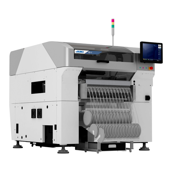
- Page 1 Fast Smart Modular Mounter RS-1/RS-1XL/RS-1R PACKING GUIDE...
- Page 2 (3) This manual is prepared with extreme care. However, if you have any question or find any error or omission in writing, contact our dealer or JUKI Corporation. (4) JUKI Corporation shall disclaim all the responsibility for any trouble resulting from the user's abnormal operation regardless of Item (3).
-
Page 3: Table Of Contents
Packing Guide Table of Contents Chapter 1 Head Unit ··············································································· 1-1 1-1 Securing the Head Unit Fixing Parts ··························································· 1-1 1-1-1 Securing the LNC Z-Axis Fixing Parts ················································· 1-1 1-1-2 Securing the ZA-Axis ······································································ 1-2 1-2 Attaching the Packing Materials ································································· 1-3 1-3 Securing the Head Unit Fixing Parts (Head Rev. -
Page 4: Chapter 1 Head Unit
Packing Guide To prevent the body from injury which can be caused by DANGER accidental activation of the machine, cut off the power to the machine before starting to work. Chapter 1 Head Unit 1-1 Securing the Head Unit Fixing Parts 1-1-1 Securing the LNC Z-Axis Fixing Parts Affix the limit damper to the ZM stopper as shown in the Fig. -
Page 5: Securing The Za-Axis
Packing Guide 1-1-2 Securing the ZA-Axis 1) Fix it with 40182877 ZA_FIXED_BRACKET as shown. There are 4 screws. SL6051092TN. 2) Attach the Caution tag to the bracket. -
Page 6: Attaching The Packing Materials
Packing Guide 1-2 Attaching the Packing Materials Cover the lower portion of the head with the rust preventive paper sheet (Oji Paper Co., Ltd. KS-VC1 Ferror-bright u-35ss-1 (for plastic)) and put desiccating agent around a part between the OCC camera unit and light unit. Desiccating agent Rust preventive... -
Page 7: Securing The Head Unit Fixing Parts (Head Rev. A And Later)
Packing Guide 1-3 Securing the Head Unit Fixing Parts (Head Rev. A and Later) 1-3-1 Securing the LNC Z-Axis Fixing Parts 1) Assemble the COVER_CUSHION (40049671) to the ZM_STOPPER (40210361) using SM4030601SC. * For the ZM stopper, assemble the rubbers to different surfaces. Therefore, two rubbers are used for one machine. -
Page 8: Securing The Za-Axis
Packing Guide Front view Caution tag (yellow) Caution tag (yellow) Part No. 40087186 should Part No. 40087186 should be used. be used. 1-3-2 Securing the ZA-Axis It should be performed as in 1-1-2. 1-4 Attaching the Packing Material (Head Rev. A and Later) It should be performed as in 1-1-2. -
Page 9: Chapter 2 X-Y Unit
Packing Guide Chapter 2 X-Y Unit 2-1 Securing the X-Axis Frame Put the X_FRAME_END assembly tightly in contact with the Y-stopper assembly and secure the Y_FIX_BR_3020 to the X_FRAME_END assembly and Y_MOTOR_FRAME with the screws, and then secure them to the X-axis frame. After securing, check to make sure that the Y stopper assembly and the X-axis frame end assembly are in intimate contact with each other. -
Page 10: Securing The Head
Packing Guide 2-2 Securing the Head Attach the set-up caution tag (yellow, part No.: 40087186) to the screw mounting oval hole part of the X_FIX_BR. Move the head to the leftmost position when viewed from the rear and push it against the X-stopper rubber. -
Page 11: Chapter 3 Board Transport Unit
Packing Guide Chapter 3 Board Transport Unit 3-1 Packing the Accessory Units Put the parts used for packaging in the cardboard box 40077701 together with the other supplied parts. (See the packing instructions for accessories.) Remove the following two units from the transport unit and pack them. <Accessory units>... -
Page 12: Packing Procedure
Packing Guide 3-2 Packing Procedure 3-2-1 Center Part When the width of the transport rail is set to the minimum board width (30 mm), put a polyethylene pad at the center part and fix it. Set the width of the transport rail to the minimum level (30 mm) and attach a filament tape to the rail plate above the screw shaft (two locations). -
Page 13: Chapter 4 Base Bridge Section
Packing Guide Chapter 4 Base Bridge Section 4-1 ATC Unit Secure the slide plate with a bundled wire band. Attach the caution tag (yellow, 40087186). Fig. 4-1-1 ATC unit... -
Page 14: General View Of Base Bridge (Atc And Vcs Light Units)
Packing Guide 4-2 General View of Base Bridge (ATC and VCS Light Units) 1) Cover the entire base bridge with rust preventive paper and secure the rust preventive paper with filament tapes. Air cap Rust preventive paper Cover the whole with rust preventive paper and fix with filament tape... -
Page 15: Chapter 5 Signal Light
Packing Guide Chapter 5 Signal Light Push the slide at the root of the signal light to lay it down toward the rear of the machine. Wind the packing material on the light portion and secure it to the main unit with a filament tape. -
Page 16: Chapter 6 Safety Cover
Packing Guide Chapter 6 Safety Cover As shown in the Fig. below, fix the safety covers with a filament tape so that they are not opened. Front Rear... - Page 17 Packing Guide * Be sure to pack the side covers of the open/close section with air caps and filament tapes so that they can be protected from the safety cover. Front Rear * Paste the filament tape on the contact surface of safety cover stopper rubber and the main body cover, and pack the safety cover.
-
Page 18: Chapter 7 Pneumatic Units
Packing Guide Chapter 7 Pneumatic Units Protect the finger valve with an air cap sheet. (Put the finger valve and screws in the carton box when packing the steel portions.) Detach the air combination from the main unit, wrap it with an air cap sheet, and put it in the carton case. -
Page 19: Chapter 8 Electric Fixed Bank
Packing Guide Chapter 8 Electric Fixed Bank This work is performed only for the electric fixed bank specifications. 8-1 Detaching the Packing Parts Detach the units and parts assembled to the machine main unit. Each assembly screw is packed with the relevant part. Reel holder assembly Trash box Fig. - Page 20 Packing Guide ② In case of “fixed bank specification”, pack the reel holder as shown below. ○Reel holder assembly Roll the air cap onto the reel holder and fix it with filament tape. Refer to chapter 14 feeder exchange trolley reel holder packaging method ○Trash box Pack the 39 separation plates with air cap and...
-
Page 21: Chapter 9 Lcd Monitor
Packing Guide Chapter 9 LCD Monitor ① Remove the monitor. ② Remove the bracket on the back of the monitor and install it in its original position. ③ Fix the bracket of the main body with the air cap and the filament tape. ④... -
Page 22: Chapter 10 Overall Machine Cover
Packing Guide Chapter 10 Overall Machine Cover 1) Affix the paper sheet stated on the next page to the top of the cover as shown in the Fig. below. (4 locations. Black and white printing is possible.) 2) Cover the entire machine main unit with a vinyl bag. Dimensions of vinyl cover:... - Page 23 Packing Guide 10-2...
-
Page 24: Chapter 11 Packing The Accessory Units
Packing Guide Chapter 11 Packing the Accessory Units 11-1 Outer Carton Case Box for accessories 40077701 Put cushion materials, such as air cap sheets or Styrofoam materials so that no gap is produced inside the carton box. Attach the content label to the outer part of the carton box (two locations). Close the bottom covers with four staples and close the carton box firmly with a tape. -
Page 25: Check List For Units And Components To Be Put In The Carton Box
1 pc. 40089308 INFO OF THE BATTERY DISPOSAL (FOR BRAZIL) 1 pc. 40186008 INSTRUCTION_BOOK_CD-ROM (RS-1) 1 pc. 40189765 CAUTIONS FOR SAFETY (RS-1) 1 pc. 40099050 COMPONENT DB SYSTEM CD-R ASM 1 pc. 40187345 EC CONFORMANCE STATEMENT (Note 3) 1 pc. -
Page 26: Chapter 12 Transport Extension (Option)
Packing Guide Chapter 12 Transport Extension (Option) When this extension is shipped in a state where it is attached to the mounter body, it must be packed as described below. (For the parts other than those described below, the packing procedure should be the same as for the board transport unit of the standard specification.) During transportation, exercise great care to prevent the transport extension from being hit, loaded or coming into contact with other objects. -
Page 27: Chapter 13 Other Optional Units
Packing Guide Chapter 13 Other Optional Units If the following optional units are mounted, pack such units as described below. Mini signal tower (Option) Remove the mini signal tower from the tie-up band and package it in a box where it was originally packaged. -
Page 28: Chapter 14 Feeder Exchange Trolley
Packing Guide Chapter 14 Feeder Exchange Trolley Pack the feeder exchange trolley as shown in the figures below. The following operations shall be performed for 40187895, 40187896, 40187897, 40187898, 40187899, and 40187900. Wrap the bank marks (at two positions) in air caps. Fix the bank with PP bands, and then attach the caution tags to the trolley (at four... - Page 29 Packing Guide Store each reel holder in the storage section, and then cover the entire storage section with air caps. Fix them with filament tapes. Fit the packaging material (40191264) that protects the plate spring section into both sides of the reel holder, and then fix them with filament tapes.
- Page 30 Packing Guide The following operations shall be performed for 40215185, 40215186, 40215187, 40215188, 40215189, and 40215190. Wrap the bank marks (at two positions) in air caps. Fix the bank with tie-up bands, and then attach the caution tags to the trolley (at four positions).
- Page 31 Packing Guide Pull out the upper reel holders and fix them with the filament tape. Fix the whole upper reel holders with the filament tape so that they do not move as shown in the left figure. Cover up the entire feeder exchange trolley with air cap.
-
Page 32: Chapter 15 Tape Set Unit (Machine Rev. D And Later)
Packing Guide Chapter 15 Tape Set Unit (Machine Rev. D and Later) Package the unit following the figure shown below. (Left front side: standard; right rear side: option) [Left front side (standard)] Fold the tape set unit and fix it with the tie-up band. - Page 33 Packing Guide [Right rear side (option)] Remove the three tie-up bands EA9500B0100 and four fixing screws SL6040892TN, and detach the tape setting unit. Put the three tie-up bands EA9500B0100 and four fixing screws SL6040892TN in a Wrap the cable terminal with air cap and bag.
-
Page 34: Chapter 16 Touch Pen (Rs-1R Only)
Packing Guide Chapter 16 Touch Pen (RS-1R Only) 1) Remove the touch pen from the LCD monitor's bracket. * The front side is attached as standard, the rear side is attached when selecting the optional rear monitor. <Front> <Rear> 2) Pack the removed touch pen and put it in the packing accessory box with other accessories. - Page 35 Revision record Rev. Date Revised locations Revision contents Remarks Feb. 2017 First edition Apr. 2017 Fully revised Step2 Revised Oct. 2018 Fully revised Addition of XL board specifications Revised Jan. 2019 Fully revised Addition of RS-1R Revised Modification of accessories check sheet Apr.
- Page 36 MANUFACTURER INQUIRY SMT TRAINING CENTER 2-11-1, Tsurumaki, Tama-shi, Tokyo 206-8551, JAPAN PHONE: 81-42-357-2295 http://www.juki.co.jp/ Copyright © 2017-2019 JUKI CORPORATION The specification and appearance may be changed without notice. All rights reserved throughout the world. Original Instructions 2019.09 Printed in Japan...