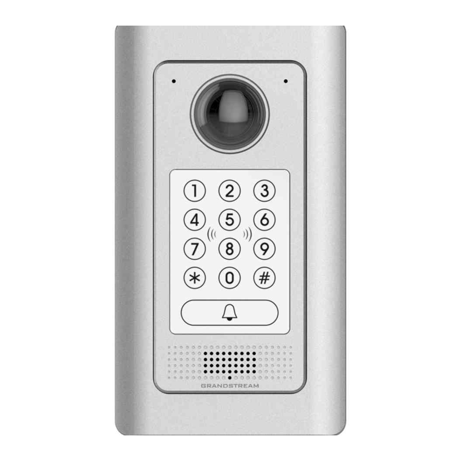
Grandstream Networks GDS3710 Quick Reference Manual
Inwall mounting kit
Hide thumbs
Also See for GDS3710:
- User manual (133 pages) ,
- Quick installation manual (47 pages) ,
- Connection manual (22 pages)
Advertisement
Quick Links
Grandstream Networks, Inc.
126 Brookline Ave, 3rd Floor
Boston, MA 02215. USA
Tel : +1 (617) 566 - 9300
Fax: +1 (617) 249 - 1987
In-Wall Mounting Kit
www.grandstream.com
Quick Reference Guide
For Warranty and RMA information, please visit
(GDS3710 NOT Included)
www.grandstream.com
Advertisement

Summary of Contents for Grandstream Networks GDS3710
- Page 1 126 Brookline Ave, 3rd Floor Boston, MA 02215. USA Tel : +1 (617) 566 - 9300 Fax: +1 (617) 249 - 1987 In-Wall Mounting Kit www.grandstream.com Quick Reference Guide For Warranty and RMA information, please visit (GDS3710 NOT Included) www.grandstream.com...
- Page 2 Content English............1...
-
Page 3: Package Contents
1 x Drill Template 1 x Plastic Box Resources/GDS3710_QIG.pdf User Manual: www.grandstream.com/sites/default/files/ Resources/GDS3710_UserManual.pdf FAQ: www.grandstream.com/our-products In-Wall Mountin g Kit Quick Reference Guide (GDS3710 NOT Included) 1 x Anti-Tamper 1 x Metal Frame 1 x Quick Hex Key Reference Guide (For Stud Mount) -
Page 4: Solid Wall Installation
Solid Wall Installation Please follow below steps to install the device into solid wall. Step 1: Use provided Drill Template to mark boundary then dig a rectangle hole into the wall (drilling or dig tools not provided) . The depth of hole is 35 mm (or 1.38 inch), marked in the template (rotating it to measure if necessary) . - Page 5 Plastic Box inside the hole just digged. Step 6: Step 4: Install the Cover Plate and fix it using the Hex Key Follow GDS3710 QIG and User Manual to connect provided. with the Anti-Tamper Screws wires to the PoE switch or PoE Injector. Connect the Electrical Lock acoording to its document.
- Page 6 Stud Installation Step 3: Mount the Installation Bracket into the Plastic Box Please follow below steps to install the device at the stud of using supplied Screws a new building open wall,or a finished wall. Step 1: For finished wall,use provided Drill Template to mark boundary and dig a rectangle hole into the wall.
- Page 7 Step 7: Step 5: Install the Cover Plate and fix it using the Hex Key Follow GDS3710 QIG and User Manual to connect with the Anti-Tamper Screws provided. wires to the PoE switch or PoE Injector. Connect the Electrical Lock acoording to its document.
- Page 8 Drywall (Hollow Wall) Installation Step 3: Please follow below steps to install the device on a drywall or Insert the Plastic Box into the cutted hole properly. hollow wall. The thickness of the wall where the clamps can handle is among 6.2 ~ 24 mm (or 0.24 ~ 0.94 inch) Step 1: Use provided Drill Template to mark boundary then cut opening on the dry wall.
- Page 9 Step 5: Step 7: Follow GDS3710 QIG and User Manual to connect Install the Cover Plate and fix it using the Hex Key wires to the PoE switch or PoE Injector. Connect the provided. with the Anti-Tamper Screws Electrical Lock acoording to its document.


