
Related Manuals for Viessmann WAGO 750-8212/000-100


Summary of Contents for Viessmann WAGO 750-8212/000-100
- Page 1 VIESMANN Installation and service instructions for contractors BMS communication with heating systems via BACnet WAGO BACnet/IP gateway WAGO BACnet/IP gateway Please keep safe. 6175460 CA 5/2021...
- Page 2 Safety instructions Safety instructions Please follow these safety instruc- tions closely to prevent accidents and material losses. Safety instructions explained Danger Note This symbol warns against the risk Details identified by the word "Note" of injury. contain additional information. Please note This symbol warns against the risk of material losses and environmen- tal pollution.
- Page 3 For replacements, only use original safe operation of the system. spare parts supplied or approved by Always replace faulty components Viessmann. with genuine Viessmann spare parts. Safety instructions for operating the system If you smell flue gas Flue systems and combustion air...
- Page 4 Safety instructions Safety instructions (cont.) Extractors Danger The simultaneous operation of the Operating appliances that extract air to boiler and appliances that extract the outside (cooker hoods, extractors, air to the outside can result in life air conditioning units, etc.) can create threatening poisoning due to negative pressure.
-
Page 5: Table Of Contents
Index Index Information Disposal of packaging ................Symbols ....................Intended use ..................Product information ................Functions .................... ■ Spare parts lists ..................Preparing for installation ........................ Installation sequence Process overview ................... Installing the gateway and power supply unit ........Arrangement on the top-hat rail ............10 ■... -
Page 6: Information Disposal Of Packaging
The gateway is only intended to be installed and oper- With regard to the communication interfaces, ensure ated in conjunction with Viessmann control units, with on site that the system requirements specified in the due attention paid to the associated installation, serv- product documentation are met at all times for every ice and operating instructions. -
Page 7: Product Information
Incorrect usage also occurs if the components in the Viessmann system are modified from their intended function. Product information The WAGO BACnet/IP gateway is used to connect Viessmann control units to BACnet systems. -
Page 8: Preparing For Installation
Preparing for installation Preparing for installation WAGO BACnet/IP gateway system overview 100 - 240 V~ 24 V CAN-BUS BACnet/IP Fig. 1 Viessmann heat generator Gateway Building management system Power supply unit Terminator 120 Laptop with web browser and WAGO Web-Visu Ω... -
Page 9: Installation Sequence
Installation sequence Process overview Step Responsibility Page Install the gateway and power supply unit. Contractor Establish the CAN bus connection. Contractor Connect the plug-in attachment. Contractor Establish the connection to BACnet. IT expert/system integrator Connect the gateway to the power supply unit Electrician Power supply Electrician... -
Page 10: Arrangement On The Top-Hat Rail
Installation sequence Installing the gateway and power supply unit (cont.) Overview of connecting cables Connecting cables Length Standard delivery: Cable cores between gateway and power supply unit 0.52 m Accessories: CAN bus cable On site: Recommended power cable 3-core: H05VV-F3G 1.5 mm ■... -
Page 11: Installing The Gateway
Installation sequence Installing the gateway and power supply unit (cont.) Installing the gateway Fig. 3 4. Affix the supplied rating plate (self-adhesive) to the electrical system in a visible location. -
Page 12: Installing The Power Supply Unit
Installation sequence Installing the gateway and power supply unit (cont.) Installing the power supply unit Fig. 4... -
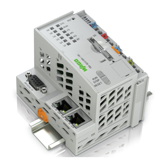
Page 13: Connections And Operating Elements
Installation sequence Connections and operating elements WAGO BACnet/IP gateway STOP RESET ‒ Fig. 5 Serial interface Operating mode switch LED status indicators Standard mode Reset button RST Factory setting: Do not adjust! Status LED for supply voltage STOP Only for update process; see WAGO commissioning manual. -
Page 14: Led Indicators
If the fault cannot be rectified, ■ contact Viessmann Werke Technical Service. Other Fault Contact Viessmann Werke Tech- nical Service. Power supply unit L N PE + + - - Fig. 6 INPUT 100 to 240 V, 50 to 60 Hz OUTPUT 24 V 1.3 A... -
Page 15: Connecting And Releasing Cores
Installation sequence Connecting and releasing cores Gateway Fig. 7 Example: BACnet/IP gateway Power supply unit Fig. 8... -
Page 16: Establishing The Can Bus Connection
Installation sequence Establishing the CAN bus connection The Viessmann CAN bus is designed for "line" bus ■ topology with a terminator at both ends (accesso- ries). ■ With CAN bus, the transmission quality and the cable lengths depend on the electrical properties of the cable: Only use cable types listed in the following table. - Page 17 Installation sequence Establishing the CAN bus connection (cont.) ‒ ‒ STOP RESET ‒ Fig. 9 CAN bus shield Plug for controlling the heat generator (stand- ard delivery of the gateway) Installation and service instructions for heat gen- erator control unit...
-
Page 18: Connecting The Plug-In Attachment
Installation sequence Connecting the plug-in attachment WAGO BACnet/IP gateway The plug-in attachment (standard delivery) must be plugged in. Do not connect the plug-in attachment until the CAN bus cable has been connected. If the gateway is at the beginning or end of the CAN bus: Fig. -
Page 19: Establishing The Connection To The Bacnet/Ip Gateway
Installation sequence Connecting the plug-in attachment (cont.) Fig. 11 Plug-in attachment (standard delivery) Terminator Establishing the connection to the BACnet/IP gateway The connection to the network must be established by the system integrator. -
Page 20: Connecting The Gateway To The Power Supply Unit
Installation sequence Establishing the connection to the BACnet/IP… (cont.) ‒ ‒ STOP RESET ‒ Fig. 12 Connect BACnet/IP via RJ45 interface Connecting the gateway to the power supply unit Connecting cores in the power supply unit... -
Page 21: Power Supply
Installation sequence Connecting the gateway to the power supply unit (cont.) ‒ ‒ ‒ ‒ STOP RESET Fig. 13 Cable cores between gateway and power supply unit (standard delivery) Power supply General information Danger Danger Incorrect wiring can lead to serious injury from Incorrect core assignment can result in serious electrical current and result in appliance dam- injury and damage to the appliance. -
Page 22: Power Supply Via The Mains Isolator
Installation sequence Power supply (cont.) Recommended power cable: 3-core Protect the power cable to the gateway power supply ■ unit with a maximum fuse rating of 16 A across all H05VV-F3G 1.5 mm poles. ■ H05RN-F3G 1.5 mm Isolators for non-grounded conductors The connection versions for the power supply descri- bed below have an effect on the characteristics of the Install an isolator in the power cable to provide... -
Page 23: Power Supply Independent Of The Mains Isolator
Installation sequence Power supply (cont.) Grounding of top-hat rail to ensure that the shield- ing of the CAN bus cable is grounded/protected against interference. Cores supplied Power supply independent of the mains isolator Effects during heating system shutdown: The control unit is switched off. ■... -
Page 24: Commissioning And Adjustment
Commissioning and adjustment Commissioning the gateway Commissioning must be carried out by the IT expert or 4. For further commissioning steps, see the "WAGO system integrator. BACnet Automation Gateway commissioning man- ual" at www.automation-gateway.info 1. Switch on the heat generator. Note 2. - Page 25 Dismounting the gateway If the gateway or power supply unit need to be dis- mounted, e.g. because the device is faulty, proceed as shown in the following diagrams. Dismounting the terminals Fig. 16...
- Page 26 Dismounting the gateway (cont.) Dismounting the controller Fig. 17...
- Page 27 Dismounting the power supply unit Fig. 18...
-
Page 28: Specification
Specification Specification WAGO BACnet/IP gateway Power supply 24 V Power consumption Max. 116 mA Nominal rating 2.8 W IP rating IP 20 Permissible ambient temperature Operation 0 to 40 °C ■ Storage 20 to +60 °C – ■ Transport 20 to +60 °C for max. 3 months or average 35 °C −... - Page 29 Specification Specification (cont.) Power supply unit Rated voltage 100 to 240 V~ Rated frequency 50 to 60 Hz Rated current 1.34 A Output voltage 24 V Protection class IP rating IP 20 Primary/secondary galvanic isolation SELV to EN 60335 Electrical safety EN 60335 Permissible ambient temperature Operation...
-
Page 30: Certificates Declaration Of Conformity
European directives and supplementary national requirements in terms of its design and operational characteristics. Viessmann Climate Solutions SE, D-35108 Allendorf, hereby declares that the radio equipment type of the named product is in compliance with Direc-... -
Page 31: Appendix
Appendix Final decommissioning and disposal Viessmann products can be recycled. Components and substances from the system are not part of ordi- nary household waste. For shutting down the system, isolate the system from the power supply and allow components to cool down where appropriate. -
Page 32: Keyword Index
Keyword index Keyword index Ambient temperature..........28, 29 Output voltage............29 Overview of connections – Gateway..............13 BACnet/IP gateway – Power supply unit............14 – Establishing the connection........19 Overview of operating elements – Gateway..............13 CAN bus connection, establishing......16 Connecting cables............10 Power consumption............28 Connection.............. - Page 36 Viessmann Manufacturing Company (U.S.) Inc. Viessmann Manufacturing Company Inc. 45 Access Road 750 McMurray Road Warwick, Rhode Island · 02886 · USA Waterloo, Ontario · N2V 2G5 · Canada TechInfo Line 1-888-484-8643 TechInfo Line 1-888-484-8643 1-800-288-0667 · Fax (401) 732-0590 1-800-387-7373 ·...