
Related Manuals for Viessmann WAGO KNX/TP gateway


Summary of Contents for Viessmann WAGO KNX/TP gateway
- Page 1 VIESMANN Installation and service instructions for contractors WAGO KNX/TP gateway BMS communication with heating systems via KNX/EIB WAGO KNX/TP gateway Please keep safe. 5853847 GB 7/2019...
- Page 2 Safety instructions Safety instructions Please follow these safety instruc- tions closely to prevent accidents and material losses. Safety instructions explained Danger Please note This symbol warns against the risk This symbol warns against the risk of injury. of material losses and environmen- tal pollution.
- Page 3 For replacements, use only original Replace faulty components only spare parts supplied or approved by with genuine Viessmann spare Viessmann. parts. Safety instructions for operating the system If you smell flue gas...
- Page 4 Safety instructions Safety instructions (cont.) Danger The simultaneous operation of the boiler and appliances that extract air to the outside can result in life threatening poisoning due to a reverse flow of flue gas. Fit an interlock circuit or take suita- ble steps to ensure an adequate supply of combustion air.
-
Page 5: Table Of Contents
Index Index Information Disposal of packaging ................Symbols ....................Intended use ..................Product information ................Functions .................... ■ Spare parts lists ..................Preparing for installation ........................ Installation sequence Process overview ................... Installing the gateway and power supply unit ........Installing the gateway ................. 11 ■... -
Page 6: Information Disposal Of Packaging
The gateway is only intended to be installed and oper- With regard to the communication interfaces, ensure ated in conjunction with Viessmann control units, with on site that the system requirements specified in the due attention paid to the associated installation, serv- product documentation are met at all times for every ice and operating instructions. -
Page 7: Product Information
Incorrect usage also occurs if the components in the Viessmann system are modified from their intended function. Product information The WAGO KNX/TP gateway is used to connect Viessmann control units to KNX/EIB systems. -
Page 8: Preparing For Installation
Preparing for installation Preparing for installation System overview 100 - 240 V~ 24 V CAN bus Fig. 1 Viessmann heat generator Gateway Building management system Power supply unit Terminator 120 Laptop with web browser and WAGO Web-Visu Ω... -
Page 9: Installation Sequence
Installation sequence Process overview Step Responsibility Page Install the gateway and power supply unit. Contractor Establish the CAN bus connection to the control unit. Contractor Use a terminator. Contractor Establish the connection to the KNX. IT expert/system integrator Power supply Electrician Commission the gateway. - Page 10 Installation sequence Installing the gateway and power supply unit (cont.) Overview of connecting cables Connecting cables Length Standard delivery: Cable cores between gateway and power supply unit 0.52 m Accessories: CAN bus cable On site: Recommended power cable 3-core: H05VV-F3G 1.5 mm ■...
-
Page 11: Installing The Gateway
Installation sequence Installing the gateway and power supply unit (cont.) Installing the gateway Fig. 3 4. Affix the supplied type plate (self-adhesive) to the system in a visible location. -
Page 12: Installing The Power Supply Unit
Installation sequence Installing the gateway and power supply unit (cont.) Installing the power supply unit Fig. 4... -
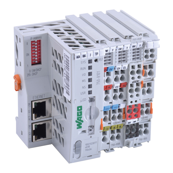
Page 13: Overview Of Connections
Installation sequence Overview of connections ‒ ‒ ‒ Fig. 5 Address selector CAN high LED status indicators KNX bus " " – Reset button RST CAN bus shield Status LED for supply voltage Shield Status LED for CAN bus interface 24 V supply voltage connection Status LED for KNX/EIP/TP interface Do not open! -
Page 14: Connecting And Releasing Cores
Installation sequence Overview of connections (cont.) Connecting and releasing cores Fig. 6 Operating elements Address selector Operating mode switch Fig. 8 Fig. 7 Standard mode Factory setting: Do not adjust! Factory setting: Do not adjust! STOP Do not adjust! RESET Do not adjust! -
Page 15: Display Elements
Check address selector. If nec- ■ essary, restore the factory set- tings as shown in the figure on page 14. If the fault cannot be rectified, ■ contact Viessmann Werke Technical Service. Other Fault Contact Viessmann Werke Tech- nical Service. -
Page 16: Power Supply Unit
100 to 240 V/50 Hz/60 Hz OUTPUT 24 V 1.3 A Establishing the CAN bus connection ■ The Viessmann CAN bus is designed for "line" bus topology with a terminator at both ends (accesso- ries). ■ With CAN bus, the transmission quality and the... -
Page 17: Connecting The Plug-In Attachment
Installation sequence Establishing the CAN bus connection (cont.) 2. Connect the CAN bus cable to connection 3. Connect the shielding of the CAN bus cable to the the heat generator control unit. The plug is part of gateway: See page 13. the standard delivery of the gateway. -
Page 18: Establishing A Connection To The Knx
Installation sequence Connecting the plug-in attachment (cont.) Fig. 13 Plug-in attachment (standard delivery) Terminator Establishing a connection to the KNX The connection to the required network must be estab- lished by the system integrator. For connections, see page 13. Power supply General information Danger The mains voltage should be single-phase, 100 to... -
Page 19: Connecting Cores In The Power Supply Unit
Installation sequence Power supply (cont.) The connection version must be selected subject to Isolators for non-earthed conductors the heating system and the required monitoring func- tion. The recommended connection version is the ■ Install an isolator in the power cable to provide "power supply via the mains isolator". - Page 20 Installation sequence Power supply (cont.) ‒ ‒ ‒ ‒ Fig. 15...
-
Page 21: Power Supply Via The Mains Isolator
Installation sequence Power supply (cont.) Power supply via the mains isolator Effects during heating system shutdown: The gateway and control unit are switched off. ■ ■ No data is transferred to the KNX/EIB control sys- tem. Danger Incorrect core assignment can result in serious injury and damage to the appliance. -
Page 22: Power Supply Independent Of The Mains Isolator
Installation sequence Power supply (cont.) Power supply independent of the mains isolator Effects during heating system shutdown: The control unit is switched off. ■ ■ The gateway remains in operation. ■ No data is transferred to the KNX/EIB control sys- tem. -
Page 23: Commissioning And Adjustment
Commissioning and adjustment Commissioning the gateway Commissioning must be carried out by the IT expert or 4. For further commissioning steps, see the "WAGO system integrator. KNX automation gateway commissioning manual" at www.automation-gateway.info 1. Switch on the heat generator. 2. Switch on the power supply for the gateway. 3. - Page 24 Dismounting the gateway Dismounting the end clamp Fig. 18 CAN terminal KNX terminal; for dismounting see following figure End clamp...
- Page 25 Dismounting the gateway (cont.) Dismounting the KNX terminal Fig. 19...
- Page 26 Dismounting the gateway (cont.) Dismounting the CAN terminal Fig. 20...
- Page 27 Dismounting the gateway (cont.) Dismounting the controller Fig. 21...
- Page 28 Dismounting the power supply unit Fig. 22...
-
Page 29: Specification
Specification Specification WAGO KNX/TP gateway Power supply 24 V Power consumption Max. 124 mA Rated power IP rating IP 20 Permissible ambient temperature Operation 0 to 40 °C ■ Storage 20 to +60 °C – ■ Transport 20 to +60 °C for max. 3 months or average 35 °C −... - Page 30 Specification Specification (cont.) Power supply unit Rated voltage 100 to 240 V~ Rated frequency 50 to 60 Hz Rated current 1.34 A Output voltage 24 V Protection class IP rating IP 20 Primary/secondary galvanic isolation SELV to EN 60335 Electrical safety EN 60335 Permissible ambient temperature Operation...
-
Page 31: Appendix
Appendix Final decommissioning and disposal Viessmann products can be recycled. Components For decommissioning the system, isolate the system and substances from the system are not part of ordi- from the power supply and allow components to cool nary household waste. -
Page 32: Certificates Declaration Of Conformity
Certificates Declaration of conformity The specialist electrical company that sets up the WAGO KNX/TP gateway and wires it for connection is responsible for the Declaration of Conformity and for affixing the CE mark. Only components from the standard delivery may be... -
Page 33: Keyword Index
Keyword index Keyword index Address selector............14 Memory card.............. 15 Ambient temperature..........29, 30 Operating mode switch..........14 CAN bus connection, establishing......16 Output voltage............30 Connecting cables............10 Overview of connections Connection..............13 – Gateway..............13 Cores – Power supply unit............16 – Connecting............14, 19 –... - Page 36 Viessmann Werke GmbH & Co. KG Viessmann Limited D-35107 Allendorf Hortonwood 30, Telford Telephone: +49 6452 70-0 Shropshire, TF1 7YP, GB Fax: +49 6452 70-2780 Telephone: +44 1952 675000 www.viessmann.com Fax: +44 1952 675040 E-mail: info-uk@viessmann.com...