Table of Contents
Advertisement
Quick Links
www.ti.com
User's Guide
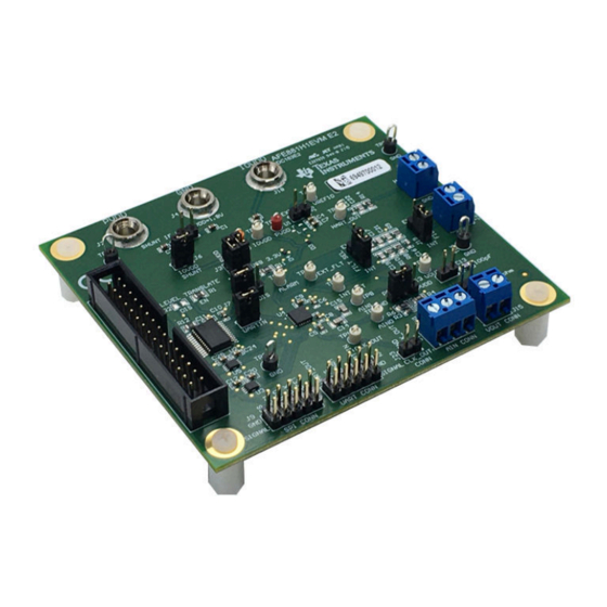
AFE881H1 Evaluation Module
This user's guide describes the characteristics, operation, and recommended use cases of the AFE881H1EVM.
This document provides examples and instructions on how to use the AFE881H1EVM board and included
software. Throughout this document, the terms evaluation board, evaluation module, and EVM are synonymous
with the AFE881H1EVM. This document also includes a schematic, reference printed circuit board (PCB)
layouts, and a complete bill of materials (BOM).
1
Overview..................................................................................................................................................................................3
Contents........................................................................................................................................................................3
1.2 Related Documentation From Texas Instruments..............................................................................................................
2 USB2ANY Interface Adapter..................................................................................................................................................
2.1 Signal Definitions for J10...................................................................................................................................................
2.2 USB2ANY Theory of Operation.........................................................................................................................................
Overview........................................................................................................................................................6
3.1 Electrostatic Discharge Caution.........................................................................................................................................
3.2 EVM Block Diagram...........................................................................................................................................................
3.3 EVM Jumper Summary......................................................................................................................................................
Definitions...............................................................................................................................................8
3.5 Connecting the USB2ANY.................................................................................................................................................
3.7 Optional EVM Operations................................................................................................................................................
4 Software Overview................................................................................................................................................................
4.1 Software Installation.........................................................................................................................................................
4.2 Launching the Software...................................................................................................................................................
Features............................................................................................................................................................13
SLAU858 - NOVEMBER 2021
Submit Document Feedback
ABSTRACT
Table of Contents
Adapter......................................................................................10
Copyright © 2021 Texas Instruments Incorporated
Table of Contents
10
11
11
12
AFE881H1 Evaluation Module
3
4
4
5
6
6
7
9
1
Advertisement
Table of Contents

Related Manuals for Texas Instruments AFE881H1


Summary of Contents for Texas Instruments AFE881H1
-
Page 1: Table Of Contents
AFE881H1EVM. This document also includes a schematic, reference printed circuit board (PCB) layouts, and a complete bill of materials (BOM). Table of Contents Overview....................................3 1.1 Kit Contents..................................3 1.2 Related Documentation From Texas Instruments......................2 USB2ANY Interface Adapter..............................2.1 Signal Definitions for J10..............................2.2 USB2ANY Theory of Operation............................3 EVM Hardware Overview................................6 3.1 Electrostatic Discharge Caution............................ - Page 2 Figure 4-3. AFE881H1EVM GUI at Launch..........................12 Figure 4-4. USB2ANY Digital Controller Connection Status......................12 Figure 4-5. AFE881H1 Register Page............................Figure 4-6. AFE881H1 High Level Tab............................Figure 4-7. Launch Script Window.............................14 Figure 4-8. Scripting Tool Recording a Macro........................... Figure 4-9. Deselecting App Execution Aliases.........................15...
-
Page 3: Overview
Newer revisions may be available from the TI web site at , or call the Texas Instruments Literature Response Center at (800) 477-8924 or the Product Information Center at (972) 644-5580. When ordering, identify the document by both title and literature number. -
Page 4: Usb2Any Interface Adapter
Ground ALARM Alarm notification; open drain. When an alarm occurs, this pin is held low. Otherwise, this pin goes to Hi-Z. SPI communication for AFE881H1 chip select MISO SPI communication for AFE881H1 digital output MOSI SPI communication for AFE881H1 digital input 3p3V 3.3-V supply voltage... -
Page 5: Usb2Any Theory Of Operation
Figure 2-2 shows the block diagram for the USB2ANY platform. This platform is a general-purpose data- acquisition system that is used on several different Texas Instruments evaluation modules. The details of operation are included in the USB2ANY Interface Adapter User's Guide. -
Page 6: Evm Hardware Overview
Supply USB2ANY AFE881H1 Transceiver/ Connector Level Shifter HART Filtering UART, CD, RTS, ALARM CLKOUT AIN0, VOUT Connections Connections AIN1 Figure 3-1. AFE881H1EVM Block Diagram AFE881H1 Evaluation Module SLAU858 – NOVEMBER 2021 Submit Document Feedback Copyright © 2021 Texas Instruments Incorporated... -
Page 7: Evm Jumper Summary
USB power. The EVM can be fully operated using only the USB2ANY connector for both power and communication. Figure 3-2. Default Header Settings for the AFE881H1EVM SLAU858 – NOVEMBER 2021 AFE881H1 Evaluation Module Submit Document Feedback Copyright © 2021 Texas Instruments Incorporated... -
Page 8: Terminal And Pin Definitions
Shunt 2-3: HART IN terminal external filter selected HART_IN Terminal 1: GND Terminal 2: HART input HART_OUT Terminal 1: GND Terminal 2: HART output AFE881H1 Evaluation Module SLAU858 – NOVEMBER 2021 Submit Document Feedback Copyright © 2021 Texas Instruments Incorporated... -
Page 9: Connecting The Usb2Any
Loose connections between the USB2ANY and the EVM may cause intermittent operation. AFE881H1EVM USB2ANY Figure 3-4. USB2ANY Connection to the AFE881H1EVM SLAU858 – NOVEMBER 2021 AFE881H1 Evaluation Module Submit Document Feedback Copyright © 2021 Texas Instruments Incorporated... -
Page 10: Connecting The Usb Cable To The Usb2Any Interface Adapter
To use an external SPI or UART controller with EVM board, disconnect the USB2ANY controller, and disable the U2 level shifter by uninstalling R13 and installing R2. AFE881H1 Evaluation Module SLAU858 – NOVEMBER 2021 Submit Document Feedback Copyright © 2021 Texas Instruments Incorporated... -
Page 11: Software Overview
To use the scripting tool, the Python ™ programming environment must also be installed. Download the latest x86 version of Python 2.7 at https://www.python.org/downloads/. SLAU858 – NOVEMBER 2021 AFE881H1 Evaluation Module Submit Document Feedback Copyright © 2021 Texas Instruments Incorporated... -
Page 12: Launching The Software
After installation, a shortcut to launch the GUI can be found in the Start menu. If installed in the default directory, the AFE881H1EVM software can also be launched by navigating to the Texas Instruments folder in the Program Files (x86) directory, as Figure 4-2 shows. -
Page 13: Software Features
Software Overview 4.3 Software Features The AFE881H1EVM GUI allows for SPI communication with the AFE881H1 and control of the device. While the entire register map is available to the user, some features have been integrated into user controls for easy operation. -
Page 14: Figure 4-6. Afe881H1 High Level Tab
Figure 4-6 shows the AFE881H1 High Level tab of the High Level Configuration Page. This tab is used to set the DAC range and outputs, ADCs controls and settings, and HART modem functions for the device. Alarms and status information are also displayed on this tab. -
Page 15: Figure 4-8. Scripting Tool Recording A Macro
Manage app execution aliases link. The next page loads a list of apps. Deselect both application installers for python.exe and python3.exe. Figure 4-9 shows the windows settings for managing application execution aliases. Figure 4-9. Deselecting App Execution Aliases SLAU858 – NOVEMBER 2021 AFE881H1 Evaluation Module Submit Document Feedback Copyright © 2021 Texas Instruments Incorporated... -
Page 16: Schematics, Pcb Layout, And Bill Of Materials
5 Schematics, PCB Layout, and Bill of Materials 5.1 Board Schematic The AFE881H1EVM schematic is shown in Figure 5-1. Figure 5-1. AFE881H1EVM Schematic AFE881H1 Evaluation Module SLAU858 – NOVEMBER 2021 Submit Document Feedback Copyright © 2021 Texas Instruments Incorporated... -
Page 17: Pcb Components Layout
Figure 5-5 show the board layout for the AFE881H1EVM. Figure 5-2. AFE881H1EVM PCB Top Layer Layout Figure 5-3. AFE881H1EVM PCB Mid Layer 1 Layout SLAU858 – NOVEMBER 2021 AFE881H1 Evaluation Module Submit Document Feedback Copyright © 2021 Texas Instruments Incorporated... -
Page 18: Figure 5-4. Afe881H1Evm Pcb Mid Layer 2 Layout
Schematics, PCB Layout, and Bill of Materials www.ti.com Figure 5-4. AFE881H1EVM PCB Mid Layer 2 Layout Figure 5-5. AFE881H1EVM PCB Bottom Layer Layout AFE881H1 Evaluation Module SLAU858 – NOVEMBER 2021 Submit Document Feedback Copyright © 2021 Texas Instruments Incorporated... -
Page 19: Bill Of Materials
Terminal Block, 3.5mm Pitch, 2x1, TH 7.0x8.2x6.5mm ED555/2DS On-Shore Technology R1, R12 2.0k RES, 2.0 k, 5%, 0.125 W, AEC-Q200 Grade 0, 0805 0805 ERJ-6GEYJ202V Panasonic SLAU858 – NOVEMBER 2021 AFE881H1 Evaluation Module Submit Document Feedback Copyright © 2021 Texas Instruments Incorporated... - Page 20 30 ppm / degC Drift, 3.9 uA, Voltage Reference, -40 DBZ0003A REF3312AIDBZR Texas Instruments to 125 degC, 3-pin SOT-23 (DBZ), Green (RoHS & no Sb/Br) AFE881H1 Evaluation Module SLAU858 – NOVEMBER 2021 Submit Document Feedback Copyright © 2021 Texas Instruments Incorporated...
- Page 21 STANDARD TERMS FOR EVALUATION MODULES Delivery: TI delivers TI evaluation boards, kits, or modules, including any accompanying demonstration software, components, and/or documentation which may be provided together or separately (collectively, an “EVM” or “EVMs”) to the User (“User”) in accordance with the terms set forth herein.
- Page 22 www.ti.com Regulatory Notices: 3.1 United States 3.1.1 Notice applicable to EVMs not FCC-Approved: FCC NOTICE: This kit is designed to allow product developers to evaluate electronic components, circuitry, or software associated with the kit to determine whether to incorporate such items in a finished product and software developers to write software applications for use with the end product.
- Page 23 www.ti.com Concernant les EVMs avec antennes détachables Conformément à la réglementation d'Industrie Canada, le présent émetteur radio peut fonctionner avec une antenne d'un type et d'un gain maximal (ou inférieur) approuvé pour l'émetteur par Industrie Canada. Dans le but de réduire les risques de brouillage radioélectrique à...
- Page 24 www.ti.com EVM Use Restrictions and Warnings: 4.1 EVMS ARE NOT FOR USE IN FUNCTIONAL SAFETY AND/OR SAFETY CRITICAL EVALUATIONS, INCLUDING BUT NOT LIMITED TO EVALUATIONS OF LIFE SUPPORT APPLICATIONS. 4.2 User must read and apply the user guide and other available documentation provided by TI regarding the EVM prior to handling or using the EVM, including without limitation any warning or restriction notices.
- Page 25 Notwithstanding the foregoing, any judgment may be enforced in any United States or foreign court, and TI may seek injunctive relief in any United States or foreign court. Mailing Address: Texas Instruments, Post Office Box 655303, Dallas, Texas 75265 Copyright © 2019, Texas Instruments Incorporated...
- Page 26 TI products. TI’s provision of these resources does not expand or otherwise alter TI’s applicable warranties or warranty disclaimers for TI products. TI objects to and rejects any additional or different terms you may have proposed. IMPORTANT NOTICE Mailing Address: Texas Instruments, Post Office Box 655303, Dallas, Texas 75265 Copyright © 2021, Texas Instruments Incorporated...