Table of Contents
Advertisement
Quick Links
www.ti.com
User's Guide
ADS8555EVM-PDK Evaluation Module
This user's guide describes the operation and use of the ADS8555 evaluation module (EVM). The ADS8555 is
a 6-channel, simultaneous sampling, 16-bit successive approximation (SAR) analog-to-digital converter (ADC).
Each input channel on the device can support true bipolar input ranges up to ±12 V. The device includes a
programmable, internally buffered voltage reverence. The ADC includes a serial programming interface (SPI)
interface and a parallel interface (word and byte mode) for data communication. Device configuration is achieved
through simple static digital input pins (hardware mode) or through communications to the SPI interface (control
register configuration in software mode). This user's guide covers the circuit description, schematic diagram, and
bill of materials for the ADS8555 circuit board. This EVM hardware and software can also be used to support
the ADS8556, ADS8557, and ADS8558 devices from this family. Other devices can be tested by desoldering the
ADC and reprogramming the EVM (see
provided later in this document.
SLAU298A – NOVEMBER 2009 – REVISED MAY 2021
Submit Document Feedback
ABSTRACT
Section
6.3). Detailed instructions for using other family members are
Copyright © 2021 Texas Instruments Incorporated
ADS8555EVM-PDK Evaluation Module
1
Advertisement
Table of Contents

Related Manuals for Texas Instruments ADS8555EVM-PDK


Summary of Contents for Texas Instruments ADS8555EVM-PDK
- Page 1 ADC and reprogramming the EVM (see Section 6.3). Detailed instructions for using other family members are provided later in this document. SLAU298A – NOVEMBER 2009 – REVISED MAY 2021 ADS8555EVM-PDK Evaluation Module Submit Document Feedback Copyright © 2021 Texas Instruments Incorporated...
-
Page 2: Table Of Contents
Microsoft ® and Windows ® are registered trademarks of Microsoft Corporation. All trademarks are the property of their respective owners. ADS8555EVM-PDK Evaluation Module SLAU298A – NOVEMBER 2009 – REVISED MAY 2021 Submit Document Feedback Copyright © 2021 Texas Instruments Incorporated... -
Page 3: Ads8555Evm-Pdk Overview
Digital low-voltage supply (DVDD = 3.3 V) is generated using USB power from the PHI controller. • Integrated or external voltage reference options are available. SLAU298A – NOVEMBER 2009 – REVISED MAY 2021 ADS8555EVM-PDK Evaluation Module Submit Document Feedback Copyright © 2021 Texas Instruments Incorporated... -
Page 4: Evm Analog Interface
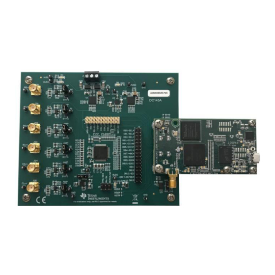
The ADS8555EVM is an evaluation module built using a two-board modular EVM system. One board is a digital controller (PHI), and the other board contains the ADC and associated analog circuitry. Both boards and the associated cables form the ADS8555EVM-PDK. 2.1 ADC Supply, Input, Voltage Reference, and Digital Connections Figure 2-1 shows the decoupling on AVDD, BVDD, HVDD, and HVSS and the voltage reference. -
Page 5: Adc Amplifier Drive
JP00 100pF 1.00k HVDD CH_A0 24.9 TP10 A0in 100nF 220pF 1.00k OPA209AIDBVR 1000pF 100nF HVSS Figure 2-2. Amplifier Drive Circuit SLAU298A – NOVEMBER 2009 – REVISED MAY 2021 ADS8555EVM-PDK Evaluation Module Submit Document Feedback Copyright © 2021 Texas Instruments Incorporated... -
Page 6: Digital Interface
ADS8555 for operation. The switch (S1) is write protected and does not need to be changed for EVM operation. EVM_ID_PWR EVM_ID_PWR R101 10.0k 100nF EVM_ID_SCL EVM_ID_SDA BR24G32FVT-3AGE2 R102 EVM_ID_WP Figure 3-1. I C Bus and EEPROM ADS8555EVM-PDK Evaluation Module SLAU298A – NOVEMBER 2009 – REVISED MAY 2021 Submit Document Feedback Copyright © 2021 Texas Instruments Incorporated... -
Page 7: Connections To The Phi Connector
10uF Zener EVM_ID_SCL TSW-116-07-G-D 3.6V BVDD 100k 100k 100k REFEN/WR QTH-030-01-L-D-A HW/SW PAR/SER TSW-103-07-G-D Figure 3-2. Connections to PHI Connector SLAU298A – NOVEMBER 2009 – REVISED MAY 2021 ADS8555EVM-PDK Evaluation Module Submit Document Feedback Copyright © 2021 Texas Instruments Incorporated... -
Page 8: Power Supplies
-15V HVSS 93.1k 10uF 10nF 10uF NR /SS DN C 10.0k 10nF TPS7A3001DRBR Figure 4-2. Low-Dropout Regulator (TPS7A3001 for HVSS) ADS8555EVM-PDK Evaluation Module SLAU298A – NOVEMBER 2009 – REVISED MAY 2021 Submit Document Feedback Copyright © 2021 Texas Instruments Incorporated... -
Page 9: Low-Dropout Regulator (Tps7A4700 For Avdd, Hvdd)
22uF 10uF 6P4V2 6P4V1 3P2V 1P6V 1µF 0P8V 0P4V 0P2V 0P1V TPS7A4700RGWR Figure 4-3. Low-Dropout Regulator (TPS7A4700 for AVDD, HVDD) SLAU298A – NOVEMBER 2009 – REVISED MAY 2021 ADS8555EVM-PDK Evaluation Module Submit Document Feedback Copyright © 2021 Texas Instruments Incorporated... -
Page 10: Installing The Ads8555Evm Software
As a part of the ADS8555EVM GUI installation, a prompt with a Device Driver Installation (as shown in Figure 5-2) appears on the screen. Click Next to proceed. Figure 5-2. Device Driver Installation Wizard Prompts ADS8555EVM-PDK Evaluation Module SLAU298A – NOVEMBER 2009 – REVISED MAY 2021 Submit Document Feedback Copyright © 2021 Texas Instruments Incorporated... - Page 11 Figure 5-3, if not already installed. Figure 5-3. LabVIEW™ Run-Time Engine Installation Verify that C:\Program Files (x86)\Texas Instruments\ADS8555EVM is as shown in Figure 5-4 after these installations. Figure 5-4. ADS8555EVM GUI Folder Post-Installation SLAU298A –...
-
Page 12: Ads8555Evm Operation
Figure 6-1. ADS8555EVM Hardware Setup and LED Indicators Select EVM GUI from start menu, or associated shortcut. Figure 6-2. Launch the EVM GUI Software ADS8555EVM-PDK Evaluation Module SLAU298A – NOVEMBER 2009 – REVISED MAY 2021 Submit Document Feedback Copyright © 2021 Texas Instruments Incorporated... -
Page 13: Jumper Settings For The Ads8555Evm
REF5025 2.5-V reference to the ADC reference input. Make sure that the GUI settings for the voltage reference match the setting on this jumper. SLAU298A – NOVEMBER 2009 – REVISED MAY 2021 ADS8555EVM-PDK Evaluation Module Submit Document Feedback Copyright © 2021 Texas Instruments Incorporated... -
Page 14: Modifying Hardware And Using Software To Evaluate Other Devices In The Family
EEPROM. connected has been updated to. Figure 6-4. Configure EEPROM and Software for the New Device ADS8555EVM-PDK Evaluation Module SLAU298A – NOVEMBER 2009 – REVISED MAY 2021 Submit Document Feedback Copyright © 2021 Texas Instruments Incorporated... -
Page 15: Evm Gui Global Settings For Adc Control And Registers
^Register Map Config_ Select sampling rate. Figure 6-5. EVM GUI Global Settings for ADC Control and Registers SLAU298A – NOVEMBER 2009 – REVISED MAY 2021 ADS8555EVM-PDK Evaluation Module Submit Document Feedback Copyright © 2021 Texas Instruments Incorporated... -
Page 16: Time Domain Display
Switching pages to any of the analysis tools described in the subsequent sections causes calculations to be performed on the same set of data. Figure 6-6. Time Domain Display ADS8555EVM-PDK Evaluation Module SLAU298A – NOVEMBER 2009 – REVISED MAY 2021 Submit Document Feedback Copyright © 2021 Texas Instruments Incorporated... -
Page 17: Frequency Domain Display
24-bit ADC. The None option corresponds to not using a window (or using a rectangular window) and is not recommended. Figure 6-7. Frequency Domain Display SLAU298A – NOVEMBER 2009 – REVISED MAY 2021 ADS8555EVM-PDK Evaluation Module Submit Document Feedback Copyright © 2021 Texas Instruments Incorporated... -
Page 18: Histogram Display
Figure 6-8, the histogram corresponding to a DC input is displayed on clicking the Capture button. Figure 6-8. Histogram Display ADS8555EVM-PDK Evaluation Module SLAU298A – NOVEMBER 2009 – REVISED MAY 2021 Submit Document Feedback Copyright © 2021 Texas Instruments Incorporated... -
Page 19: Bill Of Materials, Layout, And Schematics
30x2, Gold, SMT Header, 100mil, 16x2, Gold, TSW-116-07-G-D Samtec Header, 100mil, 10x2, Gold, TSW-110-07-G-D Samtec Header, 100mil, 3x2, Gold, TH TSW-103-07-G-D Samtec SLAU298A – NOVEMBER 2009 – REVISED MAY 2021 ADS8555EVM-PDK Evaluation Module Submit Document Feedback Copyright © 2021 Texas Instruments Incorporated... - Page 20 DGK0008A (VSSOP-8) C02, C12, C22, C32, C42, CAP, CERM, 100 pF, 50 V, +/- 100pF 885012006057 Wurth Elektronik 5%, C0G/NP0, 0603 ADS8555EVM-PDK Evaluation Module SLAU298A – NOVEMBER 2009 – REVISED MAY 2021 Submit Document Feedback Copyright © 2021 Texas Instruments Incorporated...
- Page 21 R9, R15, R17, R26, R37, RES, 0, 5%, 0.063 W, 0402 RC0402JR-070RL Yageo America R38, R40, R45 Test Point, Miniature, Black, 5001 Keystone SLAU298A – NOVEMBER 2009 – REVISED MAY 2021 ADS8555EVM-PDK Evaluation Module Submit Document Feedback Copyright © 2021 Texas Instruments Incorporated...
-
Page 22: Board Layout
Bill of Materials, Layout, and Schematics www.ti.com 7.2 Board Layout Figure 7-1 shows the PCB layout for the ADS8555EVM. Figure 7-1. Board Layout ADS8555EVM-PDK Evaluation Module SLAU298A – NOVEMBER 2009 – REVISED MAY 2021 Submit Document Feedback Copyright © 2021 Texas Instruments Incorporated... -
Page 23: Schematics
GN D 1000 pF 100n F HV S S GN D GN D GN D Figure 7-2. Amplifier Drive Schematic SLAU298A – NOVEMBER 2009 – REVISED MAY 2021 ADS8555EVM-PDK Evaluation Module Submit Document Feedback Copyright © 2021 Texas Instruments Incorporated... - Page 24 DN P GN D GN D GN D GN D GN D TP21 TP22 TP23 GN D Figure 7-3. LDO Schematic ADS8555EVM-PDK Evaluation Module SLAU298A – NOVEMBER 2009 – REVISED MAY 2021 Submit Document Feedback Copyright © 2021 Texas Instruments Incorporated...
- Page 25 100 nF 0.2 2 EVM _ID_SDA BR24G32 FVT-3AGE2 R102 EVM _ID_WP 10u F Figure 7-4. ADC, Reference, and Digital I/O Schematic SLAU298A – NOVEMBER 2009 – REVISED MAY 2021 ADS8555EVM-PDK Evaluation Module Submit Document Feedback Copyright © 2021 Texas Instruments Incorporated...
-
Page 26: Revision History
Changes from Revision * (November 2009) to Revision A (May 2021) Page • Changed entire document because of substantial changes in EVM hardware and software......1 ADS8555EVM-PDK Evaluation Module SLAU298A – NOVEMBER 2009 – REVISED MAY 2021 Submit Document Feedback Copyright © 2021 Texas Instruments Incorporated... - Page 27 STANDARD TERMS FOR EVALUATION MODULES Delivery: TI delivers TI evaluation boards, kits, or modules, including any accompanying demonstration software, components, and/or documentation which may be provided together or separately (collectively, an “EVM” or “EVMs”) to the User (“User”) in accordance with the terms set forth herein.
- Page 28 www.ti.com Regulatory Notices: 3.1 United States 3.1.1 Notice applicable to EVMs not FCC-Approved: FCC NOTICE: This kit is designed to allow product developers to evaluate electronic components, circuitry, or software associated with the kit to determine whether to incorporate such items in a finished product and software developers to write software applications for use with the end product.
- Page 29 www.ti.com Concernant les EVMs avec antennes détachables Conformément à la réglementation d'Industrie Canada, le présent émetteur radio peut fonctionner avec une antenne d'un type et d'un gain maximal (ou inférieur) approuvé pour l'émetteur par Industrie Canada. Dans le but de réduire les risques de brouillage radioélectrique à...
- Page 30 www.ti.com EVM Use Restrictions and Warnings: 4.1 EVMS ARE NOT FOR USE IN FUNCTIONAL SAFETY AND/OR SAFETY CRITICAL EVALUATIONS, INCLUDING BUT NOT LIMITED TO EVALUATIONS OF LIFE SUPPORT APPLICATIONS. 4.2 User must read and apply the user guide and other available documentation provided by TI regarding the EVM prior to handling or using the EVM, including without limitation any warning or restriction notices.
- Page 31 Notwithstanding the foregoing, any judgment may be enforced in any United States or foreign court, and TI may seek injunctive relief in any United States or foreign court. Mailing Address: Texas Instruments, Post Office Box 655303, Dallas, Texas 75265 Copyright © 2019, Texas Instruments Incorporated...
- Page 32 TI products. TI’s provision of these resources does not expand or otherwise alter TI’s applicable warranties or warranty disclaimers for TI products.IMPORTANT NOTICE Mailing Address: Texas Instruments, Post Office Box 655303, Dallas, Texas 75265 Copyright © 2021, Texas Instruments Incorporated...