Table of Contents
Advertisement
Quick Links
www.ti.com
EVM User's Guide: AM263P1, AM263P1-Q1, AM263P2, AM263P2-Q1,
AM263P4, AM263P4-Q1
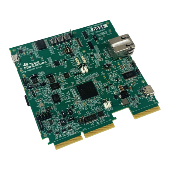
AM263Px Control Card Evaluation Module
Description
The AM263Px Control Card Evaluation Module
(EVM) is an evaluation and development board for
the Texas Instruments Sitara
microcontrollers (MCUs). This EVM provides an easy
way to start developing on the AM263Px MCUs with
on-board emulation for programming and debugging
as well as buttons and LED for a simple user
interface. The control card also enables header pin
access to key signals through the use of a high speed
edge connector (HSEC) baseboard docking station for
rapid prototyping.
Features
•
Powered through 5 V, 3 A USB type-C input
•
Multirail power supply designed for safety-relevant
applications
•
One RJ45 ethernet ports with on-board Industrial
Ethernet PHY
•
Additional ethernet add-on board connector for an
automotive or industrial ethernet PHY
SPRUJ86 – OCTOBER 2023
Submit Document Feedback
™
AM263Px series of
Copyright © 2023 Texas Instruments Incorporated
•
On-board XDS110 debug probe
•
180 pin HSEC interface for rapid prototyping
•
Three push buttons:
– PORz
– User interrupt
– RESETz
•
LEDs for:
– Power status
– User testing
– Ethernet connection
– I2C driven array
•
CAN connectivity with on-board CAN transceiver
•
Hardware resolver for accelerated motor position
sensing with two additional SAR ADC's
•
Dedicated FSI connector
•
TI test automation header
•
MMC interface to micro SD card connector
•
On-board memory
– 1 GB QSPI NAND flash
– 256 MB OSPI NOR flash
– 1 MB I2C EEPROM
AM263Px Control Card Evaluation Module
Description
1
Advertisement
Table of Contents

Related Manuals for Texas Instruments AM263P Series


Summary of Contents for Texas Instruments AM263P Series
- Page 1 – 256 MB OSPI NOR flash • Additional ethernet add-on board connector for an – 1 MB I2C EEPROM automotive or industrial ethernet PHY SPRUJ86 – OCTOBER 2023 AM263Px Control Card Evaluation Module Submit Document Feedback Copyright © 2023 Texas Instruments Incorporated...
- Page 2 TI recommends using an external power supply or accessory which complies with applicable regional safety standards such as (by example) UL, CSA, VDE, CCC, PSE. AM263Px Control Card Evaluation Module SPRUJ86 – OCTOBER 2023 Submit Document Feedback Copyright © 2023 Texas Instruments Incorporated...
-
Page 3: Kit Contents
Cryptographic acceleration and secure boot are also available on AM263Px devices. For additional information, refer to the AM263Px data sheet (SPRSP81). SPRUJ86 – OCTOBER 2023 AM263Px Control Card Evaluation Module Submit Document Feedback Copyright © 2023 Texas Instruments Incorporated... - Page 4 1.3.1 HSEC 180-pin Control Card Docking Station TMDSHSECDOCK 180-pin docking station is available for purchase through Texas Instruments. The docking station is a baseboard that enables rapid prototyping. There is a power switch on the docking station that determines whether power to the control card is supplied by the 5 V connector or USB connector.
- Page 5 Hardware 2 Hardware 2.1 Component Identification Figure 2-1. E1 Component Identification SPRUJ86 – OCTOBER 2023 AM263Px Control Card Evaluation Module Submit Document Feedback Copyright © 2023 Texas Instruments Incorporated...
-
Page 6: Power Requirements
– 5 V, 1.5 A power adapter with USB-C captive cable or receptacle – PC USB type-C port not capable of 3 A AM263Px Control Card Evaluation Module SPRUJ86 – OCTOBER 2023 Submit Document Feedback Copyright © 2023 Texas Instruments Incorporated... - Page 7 PMIC and subsequently the rest of the board via the PMIC LDO outputs. For more information about the PMIC, refer to Section 2.2.5. SPRUJ86 – OCTOBER 2023 AM263Px Control Card Evaluation Module Submit Document Feedback Copyright © 2023 Texas Instruments Incorporated...
-
Page 8: Operation
Power indicator for PMIC LDO 3.3 V supply LD[19:22] are not included in the E1 version of the Control Card. Figure 2-4. E1 Power Status LEDs AM263Px Control Card Evaluation Module SPRUJ86 – OCTOBER 2023 Submit Document Feedback Copyright © 2023 Texas Instruments Incorporated... - Page 9 Hardware 2.2.3 Power Tree Figure 2-5. Power Tree SPRUJ86 – OCTOBER 2023 AM263Px Control Card Evaluation Module Submit Document Feedback Copyright © 2023 Texas Instruments Incorporated...
-
Page 10: Power Sequence
LDO outputs are not powered on by default and require a SPI write to enable these supply rails. AM263Px Control Card Evaluation Module SPRUJ86 – OCTOBER 2023 Submit Document Feedback Copyright © 2023 Texas Instruments Incorporated... - Page 11 An independent voltage monitoring unit inside the PMIC monitors undervoltage and overvoltage on all internal supply rails and regulator outputs of the battery supply. All supplies are protected with current limiting and overtemperature warning and shutdown. SPRUJ86 – OCTOBER 2023 AM263Px Control Card Evaluation Module Submit Document Feedback Copyright © 2023 Texas Instruments Incorporated...
-
Page 12: Functional Block Diagram
Hardware www.ti.com 2.3 Functional Block Diagram Figure 2-8. AM263Px Control Card E2 Block Diagram AM263Px Control Card Evaluation Module SPRUJ86 – OCTOBER 2023 Submit Document Feedback Copyright © 2023 Texas Instruments Incorporated... - Page 13 PORz is the Power-On-Reset for the MAIN Domain. • WARMRESETn is the Warm Reset to MAIN Domain. Figure 2-10. PORz Reset Signal Tree SPRUJ86 – OCTOBER 2023 AM263Px Control Card Evaluation Module Submit Document Feedback Copyright © 2023 Texas Instruments Incorporated...
- Page 14 V_GS of the PMOS to be less than zero and so the INTn signal connects to the PMOS drain which is tied directly to ground. AM263Px Control Card Evaluation Module SPRUJ86 – OCTOBER 2023 Submit Document Feedback Copyright © 2023 Texas Instruments Incorporated...
- Page 15 Ethernet PHY reference clock signals. Figure 2-13. Crystal Clock Tree SPRUJ86 – OCTOBER 2023 AM263Px Control Card Evaluation Module Submit Document Feedback Copyright © 2023 Texas Instruments Incorporated...
-
Page 16: Boot Mode Selection
QSPI(1S), 50 MHz OSPI(8S), 50 MHz xSPI (1S->8D) , 25 MHz, SFDP DevBoot Unsupported Boot Mode All other combinations not defined above. AM263Px Control Card Evaluation Module SPRUJ86 – OCTOBER 2023 Submit Document Feedback Copyright © 2023 Texas Instruments Incorporated... -
Page 17: Header Information
– For more information about the Test Automation Header, refer to Table 2-7. Table 2-7. Test Automation Header Designator Pin 1 Pin 2 TA_GPIO3 DGND SPRUJ86 – OCTOBER 2023 AM263Px Control Card Evaluation Module Submit Document Feedback Copyright © 2023 Texas Instruments Incorporated... - Page 18 – For more information about the LIN interface, refer to Table 2-11. Table 2-11. LIN Headers Designator Pin 1 Pin 2 Pin 3 VLIN DGND VBAT_LIN DGND AM263Px Control Card Evaluation Module SPRUJ86 – OCTOBER 2023 Submit Document Feedback Copyright © 2023 Texas Instruments Incorporated...
- Page 19 MDIO signal selection for Ethernet add on board Mux Selection MDIO/MDC_MUX_SEL2 High Select line for ICSS MII0 HSEC Mux Mux Selection ICSSM0_MUX_SEL SW14 SPRUJ86 – OCTOBER 2023 AM263Px Control Card Evaluation Module Submit Document Feedback Copyright © 2023 Texas Instruments Incorporated...
-
Page 20: Push Buttons
Table 2-13. Control Card Push Buttons Push Button Signal Function SW11 INTn User Interrupt signal SW10 PORz SoC PORz reset input SW12 RESETn SoC warm reset input AM263Px Control Card Evaluation Module SPRUJ86 – OCTOBER 2023 Submit Document Feedback Copyright © 2023 Texas Instruments Incorporated... -
Page 21: Memory Interface
Table 2-14. Memory Mux Table Select Condition Mux Function HIGH OSPI NOR flash selected A→B port QSPI NAND flash selected A→C port SPRUJ86 – OCTOBER 2023 AM263Px Control Card Evaluation Module Submit Document Feedback Copyright © 2023 Texas Instruments Incorporated... - Page 22 The GPIO Expander is used to control the select signal (I2C0_MUX_SEL) of the 1:2 Mux. Table 2-15. EEPROM Mux Table Select Condition Mux Function HIGH HSEC EQEP Selected A→B2 port I2C0 Selected A→B1 port AM263Px Control Card Evaluation Module SPRUJ86 – OCTOBER 2023 Submit Document Feedback Copyright © 2023 Texas Instruments Incorporated...
-
Page 23: Ethernet Interface
HSEC, on-board Ethernet PHY, and Ethernet add-on board connector. For a complete description of all Ethernet routing for the control card, refer to Section 2.11.2.1. SPRUJ86 – OCTOBER 2023 AM263Px Control Card Evaluation Module Submit Document Feedback Copyright © 2023 Texas Instruments Incorporated... - Page 24 MDIO routing on the Control Card. The Default setting is configuration 1 which is also highlighted in green. Note Various configurations require soldering and removal of 0 Ω resistors. Figure 2-19. Ethernet Routing Overview AM263Px Control Card Evaluation Module SPRUJ86 – OCTOBER 2023 Submit Document Feedback Copyright © 2023 Texas Instruments Incorporated...
- Page 25 HSEC CPSW RGMII2 Not Connected On-board PHY High High High CPSW RGMII2 Ethernet Add-on Connector PRU1 MII1 HSEC PRU0 MII0 Not Connected SPRUJ86 – OCTOBER 2023 AM263Px Control Card Evaluation Module Submit Document Feedback Copyright © 2023 Texas Instruments Incorporated...
- Page 26 Ethernet Add-on Connector PR_MII0 or RGMII2 HSEC Not Connected On-board PHY High High Ethernet Add-on Connector PR_MII0 or RGMII2 PR_MII1 HSEC Not Connected AM263Px Control Card Evaluation Module SPRUJ86 – OCTOBER 2023 Submit Document Feedback Copyright © 2023 Texas Instruments Incorporated...
- Page 27 IO Expander and PORz. The Ethernet PHY uses many functional pins as strap option to place the device into specific modes of operation. SPRUJ86 – OCTOBER 2023 AM263Px Control Card Evaluation Module Submit Document Feedback Copyright © 2023 Texas Instruments Incorporated...
- Page 28 Green Ethernet PHY power established Yellow 10BT speed link is up Left LED Green Link OK Yellow 1000BT speed link is up AM263Px Control Card Evaluation Module SPRUJ86 – OCTOBER 2023 Submit Document Feedback Copyright © 2023 Texas Instruments Incorporated...
- Page 29 A2, A1, and A2/A1/A0 all connected to ground Note Underlined address bits are fixed based on the device addressing and cannot be configured. SPRUJ86 – OCTOBER 2023 AM263Px Control Card Evaluation Module Submit Document Feedback Copyright © 2023 Texas Instruments Incorporated...
- Page 30 SPI1_MUX_SEL of the IO Expander. Additionally, there is an external pull-down resistor on the Select line such that the PMIC routing for the SPI signals is the default state. Figure 2-24. SPI AM263Px Control Card Evaluation Module SPRUJ86 – OCTOBER 2023 Submit Document Feedback Copyright © 2023 Texas Instruments Incorporated...
- Page 31 A→B1 HIGH HSEC UART1 Selected A→B2 UART2 SOC_INTn/USER_LED0 A→B1 Selected HIGH HSEC UART2 Selected A→B2 Figure 2-26. UART 1:2 MUX to HSEC SPRUJ86 – OCTOBER 2023 AM263Px Control Card Evaluation Module Submit Document Feedback Copyright © 2023 Texas Instruments Incorporated...
- Page 32 Table 2-21. MCAN and FSI Mux Select Condition Function Low (default) MCAN signals selected A → B1 High FSI signals selected A → B2 AM263Px Control Card Evaluation Module SPRUJ86 – OCTOBER 2023 Submit Document Feedback Copyright © 2023 Texas Instruments Incorporated...
- Page 33 The AM263Px Control Card includes an XDS110 class on-board emulator. The control card also has the option to map the JTAG signals from the AM263Px SoC to the HSEC connector. Figure 2-29. JTAG SPRUJ86 – OCTOBER 2023 AM263Px Control Card Evaluation Module Submit Document Feedback Copyright © 2023 Texas Instruments Incorporated...
- Page 34 The AM263Px Control Card supports a 40 pin test automation header that allows an external controller to manipulate basic operations such as power down, PORz, warm reset, and bootmode control. Figure 2-31. Test Automation Header AM263Px Control Card Evaluation Module SPRUJ86 – OCTOBER 2023 Submit Document Feedback Copyright © 2023 Texas Instruments Incorporated...
- Page 35 GPIO Expander. Table 2-24. LIN MUX Select Logic Select Logic Condition Function LIN Selected A→B1 HIGH HSEC UART Selected A→B2 SPRUJ86 – OCTOBER 2023 AM263Px Control Card Evaluation Module Submit Document Feedback Copyright © 2023 Texas Instruments Incorporated...
- Page 36 The Write Protect (WP) and Card Detect (CD) signals of the SD card connector are pulled up to the 3.3 V IO voltage supply. A series termination resistor is provided for the MMC clock signal. AM263Px Control Card Evaluation Module SPRUJ86 – OCTOBER 2023 Submit Document Feedback Copyright © 2023 Texas Instruments Incorporated...
- Page 37 The AM263Px Control Card supports 24 ADC signal channels that are mapped for the AM263Px SoC and terminated to the HSEC connector. All ADC signals are ESD protected (TPD4E001DBVR). Figure 2-34. E1 ADC HSEC Connections SPRUJ86 – OCTOBER 2023 AM263Px Control Card Evaluation Module Submit Document Feedback Copyright © 2023 Texas Instruments Incorporated...
- Page 38 ADC and DAC. Table 2-28. VREF Switch VREF Switch Position Reference Selection Pin 1-2 On board 1.8 V Reference (REF3318AIDBZT) Pin 2-3 HSEC VREF AM263Px Control Card Evaluation Module SPRUJ86 – OCTOBER 2023 Submit Document Feedback Copyright © 2023 Texas Instruments Incorporated...
- Page 39 Output of VREF Switch Pin 4-5 OPEN - Allow for reference to be AM263Px on-die LDO reference Pin 5-6 Output of VREF Switch SPRUJ86 – OCTOBER 2023 AM263Px Control Card Evaluation Module Submit Document Feedback Copyright © 2023 Texas Instruments Incorporated...
- Page 40 EPWM4_B, FSITX1_CLK, GPIO52, EPWM1_B EPWM6_B, SPI5_D1, FSIRX1_D0, GPIO56, EPWM6_B EPWM6_B F3 EPWM5_A EPWM5_A, SPI5_CS0, FSITX1_D0, GPIO53 EPWM7_A, SPI6_CS0, FSIRX1_D1, GPIO57, EPWM7_A EPWM7_A F4 AM263Px Control Card Evaluation Module SPRUJ86 – OCTOBER 2023 Submit Document Feedback Copyright © 2023 Texas Instruments Incorporated...
- Page 41 ICSS_MII0_RXLINK G15 EPWM23_A, GPIO89, EPWM22_B 123 K15 ICSS_MII0_RXCLK PR0_PRU0_GPIO6, RMII2_REF_CLK, RGMII2_RXC, MII2_RXCLK, EPWM24_A, PR0_PRU0_GPIO4, RGMII2_RX_CTL, MII2_RXDV, EPWM24_B, GPIO92, ICSS_MII0_RXDV K16 GPIO91, EPWM24_A EPWM24_B SPRUJ86 – OCTOBER 2023 AM263Px Control Card Evaluation Module Submit Document Feedback Copyright © 2023 Texas Instruments Incorporated...
- Page 42 MMC_SDCD, UART0_CTSn, I2C2_SDA, MCAN5_TX, EPWM20_B, GPIO84, HSEC_MMC0_SDCD A5 SDFM1_CLK3, EPWM20_A SDFM1_D3, EPWM20_B PMIC_COMP2_IN+ PMIC_COMP2_IN+ PMIC_WKUP2 PMIC_COMP2_IN- PMIC_COMP2_IN- PMIC_COMP1_IN+ PMIC_COMP1_IN+ PMIC_COMP1_IN- PMIC_COMP1_IN- PMIC_SAFE_OUT2 PMIC_SAFE_OUT2 HSEC_5V0 HSEC_5V0 AM263Px Control Card Evaluation Module SPRUJ86 – OCTOBER 2023 Submit Document Feedback Copyright © 2023 Texas Instruments Incorporated...
- Page 43 GPIO44 EPWM0_B EPWM1_A EPWM1_A GPIO45 EPWM1_A EPWM1_B EPWM1_B GPIO46 EPWM4_B EPWM2_A EPWM2_A GPIO47 EPWM2_A EPWM2_B EPWM2_B GPIO48 EPWM2_B EPWM3_A EPWM3_A GPIO49 EPWM3_A SPRUJ86 – OCTOBER 2023 AM263Px Control Card Evaluation Module Submit Document Feedback Copyright © 2023 Texas Instruments Incorporated...
- Page 44 GPIO88 PR0_PRU0_GPIO1 PR0_PRU0_GPIO1 RMII2_CRS_DV PR0_UART0_RT MII2_CRS EPWM23_A GPIO89 EPWM22_B PR0_PRU0_GPIO8 PR0_PRU0_GPIO8 EPWM23_B GPIO90 EPWM29_A PR0_PRU0_GPIO6 PR0_PRU0_GPIO6 RMII2_REF_CLK RGMII2_RXC MII2_RXCLK EPWM24_A GPIO91 EPWM24_A AM263Px Control Card Evaluation Module SPRUJ86 – OCTOBER 2023 Submit Document Feedback Copyright © 2023 Texas Instruments Incorporated...
- Page 45 PR0_PRU1_GPIO1 UART3_RXD PR0_IEP0_EDC_ TRC_CLK XBAROUT13 GPIO119 EQEP1_A SYNC_OUT0 PR0_PRU1_GPIO1 PR0_PRU1_GPIO1 UART3_TXD PR0_IEP0_EDIO TRC_CTL XBAROUT14 GPIO120 EQEP1_B _DATA_IN_OUT3 EXT_REFCLK0 EXT_REFCLK0 XBAROUT15 GPIO121 EQEP1_INDEX SPRUJ86 – OCTOBER 2023 AM263Px Control Card Evaluation Module Submit Document Feedback Copyright © 2023 Texas Instruments Incorporated...
- Page 46 ADC0_AIN0 ADC0_AIN0 ADC0_AIN1 ADC0_AIN1 ADC0_AIN2 ADC0_AIN2 ADC0_AIN3 ADC0_AIN3 ADC0_AIN4 ADC0_AIN4 ADC0_AIN5 ADC0_AIN5 ADC1_AIN0 ADC1_AIN0 ADC1_AIN1 ADC1_AIN1 ADC1_AIN2 ADC1_AIN2 ADC1_AIN3 ADC1_AIN3 ADC1_AIN4 ADC1_AIN4 AM263Px Control Card Evaluation Module SPRUJ86 – OCTOBER 2023 Submit Document Feedback Copyright © 2023 Texas Instruments Incorporated...
- Page 47 RSVD_U1 RSVD_U1 VSYS_MON VSYS_MON RSVD_U3 RSVD_U3 RSVD_V2 RSVD_V2 ADC_CAL2 ADC_CAL2 ADC_R0_AIN0 ADC_R0_AIN0 ADC_R0_AIN1 ADC_R0_AIN1 ADC_R0_AIN2 ADC_R0_AIN2 ADC_R0_AIN3 ADC_R0_AIN3 ADC_VREFLO_G3 ADC_VREFLO_G3 ADC_VREFHI_G3 ADC_VREFHI_G3 SPRUJ86 – OCTOBER 2023 AM263Px Control Card Evaluation Module Submit Document Feedback Copyright © 2023 Texas Instruments Incorporated...
- Page 48 Pinlist Mode0 Mode1 Mode2 Mode3 Mode4 Mode5 Mode6 Mode7 Mode8 Mode9 Mode10 ADC_R1_AIN0 ADC_R1_AIN0 ADC_R1_AIN1 ADC_R1_AIN1 ADC_R1_AIN2 ADC_R1_AIN2 ADC_R1_AIN3 ADC_R1_AIN3 ADC_CAL3 ADC_CAL3 AM263Px Control Card Evaluation Module SPRUJ86 – OCTOBER 2023 Submit Document Feedback Copyright © 2023 Texas Instruments Incorporated...
-
Page 49: Additional Information
The E1 AM263Px Control Card had a blue-wire fix to enable the CPSW RGMII2 Gigabit ethernet port with the associated MDIO. The changes are listed below: SPRUJ86 – OCTOBER 2023 AM263Px Control Card Evaluation Module Submit Document Feedback Copyright © 2023 Texas Instruments Incorporated... - Page 50 TCAN1043A-Q1 CAN FD Transceiver • XDS110 JTAG Debug Probe • DP83869HM 10/100/1000 Ethernet Physical Layer Transceiver • LMK1C110x LVCMOS Clock Buffer • TLIN2029-Q1 LIN Transceiver AM263Px Control Card Evaluation Module SPRUJ86 – OCTOBER 2023 Submit Document Feedback Copyright © 2023 Texas Instruments Incorporated...
- Page 51 STANDARD TERMS FOR EVALUATION MODULES Delivery: TI delivers TI evaluation boards, kits, or modules, including any accompanying demonstration software, components, and/or documentation which may be provided together or separately (collectively, an “EVM” or “EVMs”) to the User (“User”) in accordance with the terms set forth herein.
- Page 52 www.ti.com Regulatory Notices: 3.1 United States 3.1.1 Notice applicable to EVMs not FCC-Approved: FCC NOTICE: This kit is designed to allow product developers to evaluate electronic components, circuitry, or software associated with the kit to determine whether to incorporate such items in a finished product and software developers to write software applications for use with the end product.
- Page 53 www.ti.com Concernant les EVMs avec antennes détachables Conformément à la réglementation d'Industrie Canada, le présent émetteur radio peut fonctionner avec une antenne d'un type et d'un gain maximal (ou inférieur) approuvé pour l'émetteur par Industrie Canada. Dans le but de réduire les risques de brouillage radioélectrique à...
- Page 54 www.ti.com EVM Use Restrictions and Warnings: 4.1 EVMS ARE NOT FOR USE IN FUNCTIONAL SAFETY AND/OR SAFETY CRITICAL EVALUATIONS, INCLUDING BUT NOT LIMITED TO EVALUATIONS OF LIFE SUPPORT APPLICATIONS. 4.2 User must read and apply the user guide and other available documentation provided by TI regarding the EVM prior to handling or using the EVM, including without limitation any warning or restriction notices.
- Page 55 Notwithstanding the foregoing, any judgment may be enforced in any United States or foreign court, and TI may seek injunctive relief in any United States or foreign court. Mailing Address: Texas Instruments, Post Office Box 655303, Dallas, Texas 75265 Copyright © 2023, Texas Instruments Incorporated...
-
Page 56: Important Notice
TI products. TI’s provision of these resources does not expand or otherwise alter TI’s applicable warranties or warranty disclaimers for TI products. TI objects to and rejects any additional or different terms you may have proposed. IMPORTANT NOTICE Mailing Address: Texas Instruments, Post Office Box 655303, Dallas, Texas 75265 Copyright © 2023, Texas Instruments Incorporated...