Nedap TRANSIT Entry Installation Manual
Hide thumbs
Also See for TRANSIT Entry:
- Quick reference (7 pages) ,
- Quick reference (4 pages) ,
- Installation manual (30 pages)
Table of Contents
Advertisement
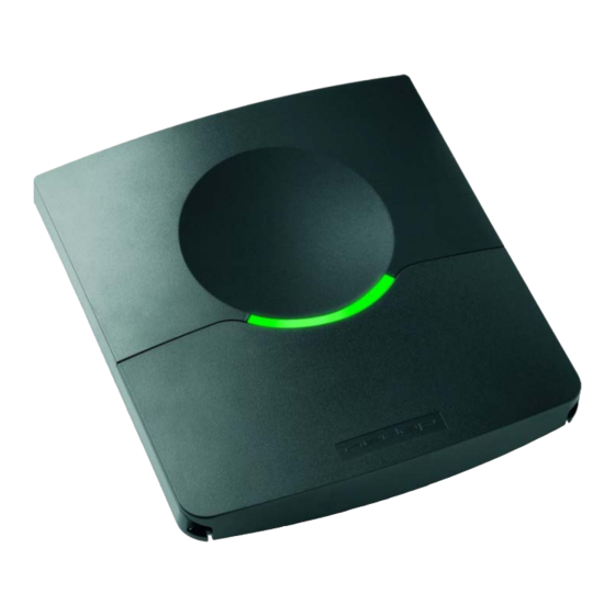
TRANSIT Entry
Installation Guide
FCC ID: CGD-TRANSITENTRY
This device complies with part 15 of the FCC rules. Operation is subject to the following two
conditions: (1) this device may not cause harmful interference, and (2) this device must accept
any interference received, including interference that may cause undesired operation.
Changes or modifications not expressly approved by the party responsible for compliance
could void the user's authority to operate the equipment.
2007-09-26
Part #: 5268605
This information is furnished for guidance, and with no guarantee as to its accuracy or completeness; its
publication conveys no license under any patent or other right, nor does the publisher assume liability for any
consequence of its use; specifications and availability of goods mentioned in it are subject to change without
notice; it is not to be reproduced in any way, in whole or in part, without the written consent of the publisher.
© Nedap IDEAS, P.O. Box 103, NL-7140 AC GROENLO
Page 1 of 27
Advertisement
Table of Contents

Related Manuals for Nedap TRANSIT Entry


Summary of Contents for Nedap TRANSIT Entry
- Page 1 © Nedap IDEAS, P.O. Box 103, NL-7140 AC GROENLO Page 1 of 27...
-
Page 2: Table Of Contents
FREQUENCY SELECTION ......................22 READ RANGE CONTROL (SQUELCH) .................23 PRINCIPLE ........................23 READ RANGE ADJUSTING..................23 IDENTIFICATION ........................24 STANDARD OPERATING PROCEDURE..............24 USING THE MTR MODULE..................24 FIRMWARE UPGRADE ......................25 TECHNICAL SPECIFICATIONS....................26 PART NUMBERS.........................27 © Nedap IDEAS, P.O. Box 103, NL-7140 AC GROENLO Page 2 of 27... -
Page 3: Introduction
(12 feet) to present a card. The handsfree access system is made up of a TRANSIT Entry reader and a transponder. TRANSIT Entry readers are installed next to a door or gate. A long range transponder visible in line of sight of the reader will be identified at... -
Page 4: Installation
• Disconnect the power supply before removing or installing any parts. • To be sure of safety, do not modify or add anything to the TRANSIT Entry other than mentioned in this installation guide or indicated by NEDAP N.V. -
Page 5: Adjustable Mounting Bracket
Once the adjustable mounting bracket is assembled, attach the bracket to the wall or mast. After that the TRANSIT Entry can be mounted onto the bracket. The ball and socket joint can be used to adjust the reader’s orientation. Tighten the hex screw on top of the joint to fix the correct orientation. -
Page 6: Opening The Service Cover
Figure 4: Opening the service cover Note: Make sure the screws are completely opened (and closed when placing the cover back on). Don’t worry about losing the screws, they cannot fall out. © Nedap IDEAS, P.O. Box 103, NL-7140 AC GROENLO Page 6 of 27... -
Page 7: Installing An Optional Interface Board
2.5.1 AVAILABLE INTERFACE BOARDS Various optional interface boards are also available for the TRANSIT Entry. Ethernet (TCP/IP) interface board Connects the TRANSIT Entry to an Ethernet network using the TCP/IP protocol. -
Page 8: Installation Procedure
2.5.2 INSTALLATION PROCEDURE 1. Disconnect the power supply. 2. Remove the complete front cover from the TRANSIT Entry. 3. Place the interface board on the 14-pin header K1. Make sure it’s firmly positioned and makes good contact with connector K1. -
Page 9: Connections
TRANSIT Entry 3 CONNECTIONS Wire connections to the TRANSIT Entry are user friendly spring cage terminal connectors. Connection procedure with spring cage terminal connectors. 1. Strip wire lead for about 9 mm ( 0.35 inch 2. Push the screwdriver straight down to release the... -
Page 10: Power Supply
TRANSIT Entry 3.1 POWER SUPPLY The TRANSIT Entry requires DC power supply in the range from 12 – 24V. Maximum current consumption is 1A @ 12VDC, 0.5A @ 24VDC. Connections: Power supply 0V. Should be connected to a protective earth connection. -
Page 11: Communication
TRANSIT Entry 3.2 COMMUNICATION 3.2.1 RS232 CONNECTION The TRANSIT Entry has an on-board RS232 interface. This interface does not support any hardware handshake signals. The communication protocol, baud rate, data format and flow control depend upon the reader firmware. See firmware manual for details. -
Page 12: Rs422 Connection
TRANSIT Entry 3.2.2 RS422 CONNECTION The TRANSIT Entry has an on-board RS422 interface. The communication protocol, baud rate, data format and flow control depend upon the reader firmware. See firmware manual for details. The RS422 interface is similar to the RS232 interface. The RS422 interface is commonly used where longer cable lengths are required. -
Page 13: Wiegand, Magstripe, Barcode Connection
Data-0 (green) Clock OUT3 Data-1 (white) Data Data Ground (black) Ground Ground Note: Maximum cable length 150 meters ( 500 feet DATA-0 DATA-1 Figure 10: Wiegand wiring © Nedap IDEAS, P.O. Box 103, NL-7140 AC GROENLO Page 13 of 27... -
Page 14: Usb Connection
TRANSIT Entry 3.2.4 USB CONNECTION The TRANSIT Entry features an USB interface for service and installation purposes. The USB connector (Type B) is accessible behind the service cover. USB type B Figure 11: USB interface Note: While the USB interface is in use, the on-board RS232 and RS422 interfaces are disabled. -
Page 15: Digital I/O
Relay contact normally open Contact ratings: Max. switching current: Max. switching voltage: 250VAC / 220VDC Max. switching power: 62.5VA / 60W CONTACT SUPPLY Figure 12: Relay output © Nedap IDEAS, P.O. Box 103, NL-7140 AC GROENLO Page 15 of 27... -
Page 16: Read Disable Input
TRANSIT Entry 3.3.2 READ DISABLE INPUT The reading of the TRANSIT Entry can be completely disabled with the RDIS input. This input is commonly used in combination with a sensor (e.g. inductive loop) that detects the presence of a person or vehicle. Use always a relay contact to connect the internal 5V to the RDIS input. -
Page 17: General Purpose Inputs
TRANSIT Entry 3.3.3 GENERAL PURPOSE INPUTS Three general purpose inputs are available on the TRANSIT Entry reader. The inputs are active low. Connections: General purpose input 1 General purpose input 2 General purpose input 3 Ground General purpose inputs Figure 14: GPIO inputs ©... -
Page 18: General Purpose Outputs
TRANSIT Entry 3.3.4 GENERAL PURPOSE OUTPUTS Three general purpose inputs are available on the TRANSIT Entry reader. The installed firmware may use these outputs for synchronous communication interfaces such as Wiegand, Barcode and Magstripe. See chapter 3.2.3 for more details. -
Page 19: Tamper Switch
An internal magnet provides tamper indication when the service cover is opened. This contact may be connected to an external alarm system. The contacts are normally closed when the cover is in place. Tamper switches of multiple TRANSIT Entry reader may be connected in series. Connections: Tamper switch (normally closed) -
Page 20: Dip-Switch Settings
USB connector is in use or when the TCP/IP interface board is installed. 4.3 UNUSED SW1-3 AND SW1-4 The switches SW1-3 and SW1-4 are reserved for future use. It is recommended to leave these switches in the ON position. © Nedap IDEAS, P.O. Box 103, NL-7140 AC GROENLO Page 20 of 27... -
Page 21: Led Indications
TRANSIT Entry 5 LED INDICATIONS A number of LED’s indicate the current status of the TRANSIT Entry reader. Figure 18: LED locations Table 1 below describes the function of each LED. Description LED bar indicating the received tag signal strength. This LED bar may also indicate RX LEVEL the presence of radio interference. -
Page 22: Frequency Selection
TRANSIT Entry 6 FREQUENCY SELECTION The TRANSIT Entry reader operates in the 2.45GHz frequency band. When two or more readers are within a range of 15 meters , these readers should be set on (50 feet) a different operating frequency. The selected frequency has to comply with local radio regulations. -
Page 23: Read Range Control (Squelch)
7 READ RANGE CONTROL (SQUELCH) 7.1 PRINCIPLE The read range of the TRANSIT Entry can be controlled with the embedded squelch function. The squelch references the received signal strength against the squelch level setting. When the received signal strength is below the squelch level no identification is possible. -
Page 24: Identification
TRANSIT Entry 8 IDENTIFICATION The TRANSIT Entry reader is always reading (except when disabled with the read disable input, see chapter 3.3.2). Automatically upon identification of a transponder the relay will be activated, the ‘smile’ lights-up and an event message is generated on the communication interface(s). -
Page 25: Firmware Upgrade
TRANSIT Entry 9 FIRMWARE UPGRADE The firmware in the TRANSIT Entry’s processor can be upgraded by means of the serial interface (RS232, RS422 or USB). The upgrade is performed by the ‘PIC downloader’ application. The upgrade procedure is described below. -
Page 26: Atechnical Specifications
50 G, 6 ms, 10x3 dir IEC68-2-27 Ea Bump 25 G, 6 ms, 1000x3 dir IEC68-2-29 Eb Random vibration 5 – 150Hz, 5 G, 20 sweeps x 3 dir EN50155 © Nedap IDEAS, P.O. Box 103, NL-7140 AC GROENLO Page 26 of 27... -
Page 27: Part Numbers
Adjustable mounting bracket 9875840 part number: TRANSPONDERS Compact Tag 9891900 part number: Window Button 9882650 part number: Window Button Switch 9882480 part number: For full product information visit www.nedapavi.com © Nedap IDEAS, P.O. Box 103, NL-7140 AC GROENLO Page 27 of 27...