Table of Contents
Advertisement
Quick Links
Advertisement
Table of Contents

Related Manuals for Abit AI7-G


Summary of Contents for Abit AI7-G
- Page 1 AI7/AI7-G Socket 478 System Board User’s Manual 4200-0392-03 Rev. 1.01...
- Page 2 No part of this manual may be reproduced, transmitted or transcribed without the expressed written permission of the manufacturer and authors of this manual. If you do not properly set the motherboard settings, causing the motherboard to malfunction or fail, we cannot guarantee any responsibility. AI7/AI7-G...
-
Page 3: Table Of Contents
Table Of Contents 快速安裝指引 .................... 2 クイックインストールガイド..............4 Schnellinstallationsanleitung..............6 Guide d’Installation Rapide ..............8 Краткое руководство по установке ........... 10 Guida all’installazione veloce ..............12 Chapter 1. Introduction ................1-1 1-1. Features & Specifications ................1-1 1-2. Layout Diagram ..................1-3 Chapter 2. - Page 4 Install Audio Driver ................. C-1 Appendix D. Install LAN Driver ................D-1 Appendix E. Install USB 2.0 Driver ..............E-1 Appendix F. Install ABIT µGuru Utility .............. F-1 Appendix G. POST Code Definition ..............G-1 Appendix H. Troubleshooting (Need Assistance?)..........H-1 Appendix I.
- Page 5 User’s Manual...
-
Page 6: 快速安裝指引
快速安裝指引 快速安裝指引 安裝處理器的散熱片以及風扇組件 (Zero Insertion Force, ZIF) ® ® Socket 478 Intel Pentium 4 CPU ® Pentium 4 Socket 478 Socket 478 ® 注意: Pentium 注意: AI7/AI7-G... - Page 7 快速安裝指引 將主機板安裝到機殼上 安裝記憶體模組 槽 DIMM 抓 碰 DIMM 點 憶體 榫子 槽 DIMM 榫 4. 穩 憶體 DIMM 槽 槽 自 DIMM 憶體 缺口 槽 DIMM DIMM 取 同時 槽 DIMM DIMM DIMM 抽取 注意:靜 造成 加 子元 損壞 進行 些 序 前 藉...
-
Page 8: クイックインストールガイド
クイックインストールガイド クイックインストールガイド CPU ヒートシンクとファンアセンブリの取り付け ZIF ( ® ® ) Socket 478 Intel Pentium ® Pentium Socket 478 ® 注意:Pentium AI7/AI7-G... - Page 9 クイックインストールガイド 注意: マザーボードをシャーシに取り付ける RAM モジュールの取り付け DIMM 2. DIMM DIMM DIMM 5. DIMM 注意 : コネクタ、ヘッダ、スイッチおよびアダプタ SCSI 電源コネクタを ATX12V 電源コネクタに差し込む 出 ATX12V 奥 着 BIOS のセットアップ ハ ウ 了 BIOS Setup 移 User’s Manual...
-
Page 10: Schnellinstallationsanleitung
5. Drücken Sie den Halteclip auf beiden Seiten von Lüfter und Haltemechanismuseinheit nieder, bis er in die Basis des Haltemoduls einschnappt. 6. Lüfter und Haltemechanismus-Einheit und die Basis des Haltemoduls sollten nun fest miteinander verriegelt sein und das Kühlblech sich in ihrem Innern befinden.. AI7/AI7-G... - Page 11 Schnellinstallationsanleitung Achtung: Vergessen Sie nicht, die korrekte Busfrequenz und -Multiplikator für Ihren Prozessor einzustellen. Installieren der Hauptplatine im Gehäuse Nach der Installation des Prozessors können Sie anfangen die Hauptplatine im Computergehäuse zu befestigen. Die meisten Gehäuse haben eine Bodenplatte, auf der sich eine Reihe von Befestigungslöcher befinden, mit deren Hilfe Sie die Hauptplatine sicher verankern können und zugleich Kurzschlüsse verhindern.
-
Page 12: Guide D'installation Rapide
Ventilateur et du Mécanisme de Retient pour verrouiller ensemble avec la Base du Module de Retient. 6. Le Ventilateur, le Mécanisme de Retient et la Base du Module de Retient doivent maintenant être verrouillés l’un sur l’autre avec le dissipateur de chaleur à l’intérieur. AI7/AI7-G... - Page 13 Guide d’Installation Rapide Attention: N’oubliez pas de programmer la fréquence de bus correcte et le multiple pour votre processeur. Installer la Carte Mre dans le Châssis Une fois que vous aurez installé le processeur sur la carte mère, vous pourrez commencer à fixer la carte mère sur le châssis.
-
Page 14: Краткое Руководство По Установке
фиксатора вентилятора и фиксирующего механизма вошли в предназначенные отверстия и защелкнулись. 5. Зафиксируйте вентилятор на основании радиатора, опустив рычажки, расположенные с обеих сторон фиксирующего механизма. 6. Вентилятор, фиксирующий механизм и основание радиатора должны быть надежно закреплены вместе с вентилятором. AI7/AI7-G... - Page 15 Краткое руководство по установке Внимание: Установите соответствующие частоту и кратность шины процессора. Установка материнской платы в корпус После установки процессора на материнскую плату можно начинать установку материнской платы в корпус. Большая часть корпусов оборудована основанием, в котором проделаны монтажные отверстия, которые позволяют надежно закрепить материнскую плату и предотвратить короткие...
-
Page 16: Guida All'installazione Veloce
6. La ventolina, il gruppo del meccanismo di trattenimento e la base del modulo di trattenimento ora dovrebbero essere fissati gli uni agli altri trattenendo al loro interno il dispersore di calore. Attenzione: Non dimenticare di impostare la corretta frequenza multipla e BUS per il processore. AI7/AI7-G... - Page 17 Guida all’installazione veloce Installazione della scheda madre sul telaio Dopo avere installato il processore sulla scheda madre si può iniziare a fissare la scheda madre sul telaio. Innanzi tutto è necessario fissare la scheda madre al telaio. La maggior parte dei telai ha una base sulla quale sono presenti diversi fori di montaggio che permettono di fissare in modo accurato la scheda madre e, allo stesso tempo, di prevenire corto circuiti.
- Page 18 AI7/AI7-G...
-
Page 19: Chapter 1. Introduction
4. AGP • Accelerated Graphics Port connector supports AGP 8X/4X Interface (0.8V/1.5V) 5. LAN • Onboard 10/100/1000M LAN Controller (AI7-G) • Onboard 10/100M LAN Controller (AI7) 6. Serial ATA RAID • Onboard 2 channels of Serial ATA 150MB/s data transfer rate with RAID function (RAID 0/RAID 1) via ICH5R South Bridge 7. - Page 20 2x USB 2.0, 1x RJ-45 LAN Connector 12. Miscellaneous • ATX form factor (305 x 245 mm) • Hardware Monitoring – including Fan Speed, Voltages, CPU and system temperature Specifications and information contained herein are subject to change without notice. AI7/AI7-G...
-
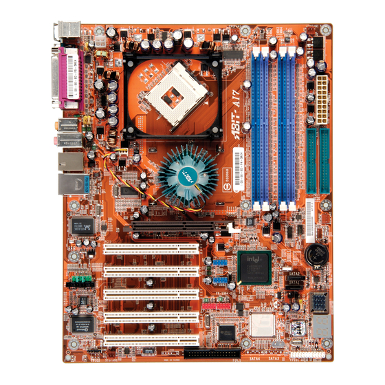
Page 21: Layout Diagram
Introduction 1-2. Layout Diagram User’s Manual... - Page 22 Chapter 1 Chapter 1 AI7/AI7-G AI7/AI7-G...
-
Page 23: Chapter 2. Hardware Setup
Hardware Setup Chapter 2. Hardware Setup Before the Installation: Turn off the power supply switch (fully turn off the +5V standby power), or disconnect the power cord before installing or unplugging any connectors or add-on cards. Failing to do so may cause the motherboard components or add-on cards to malfunction or damaged. 2-1. -
Page 24: Install Pentium ® 4 Cpu And Heatsink Supporting-Base
Retention Module Base. 6. The Fan and Retention Mechanism Assembly and Retention Module Base should now firmly lock up with each other with the heatsink inside. ATTENTION: Do not forget to set the correct bus frequency and multiple for your processor. AI7/AI7-G... -
Page 25: Install System Memory
Hardware Setup 2-3. Install System Memory This motherboard provides four 184-pin DDR DIMM slots for Single/Dual Channel DDR 400/333/266 memory modules with memory expansion size up to 4GB. To reach the performance of Dual Channel DDR, the following rules must be obeyed: •... - Page 26 DIMM module. ATTENTION: Static electricity can damage the electronic components of the computer or optional boards. Before starting these procedures, ensure that you are discharged of static electricity by touching a grounded metal object briefly. AI7/AI7-G...
-
Page 27: Connectors, Headers And Switches
Hardware Setup 2-4. Connectors, Headers and Switches Here we will show you all of the connectors, headers and switches, and how to connect them. Please read the entire section for necessary information before attempting to finish all the hardware installation inside the computer chassis. -
Page 28: Fan Connectors
The CPU must be kept cool by using a powerful fan with heatsink. The system is capable of monitoring the speed of the CPU fan. • CPUFAN1: CPU Fan • NBFAN1: Chipset Fan • SYSFAN1: System Fan • AUXFAN1, AUXFAN2: Auxiliary Fan WARNING: These fan connectors are not jumpers. DO NOT place jumper caps on these connectors. AI7/AI7-G... -
Page 29: Cmos Memory Clearing Header
Hardware Setup (3). CMOS Memory Clearing Header This header uses a jumper cap to clear the CMOS memory. • Pin 1-2 shorted (default): Normal operation. • Pin 2-3 shorted: Clear CMOS memory. WARNING: Turn the power off first (including the +5V standby power) before clearing the CMOS memory. -
Page 30: Wake-Up Header
Pin 1-2 shorted (default): Disable wake-up function support at USB1 port. Pin 2-3 shorted: Enable wake-up function support at USB1 port. • USB-PWR2: Pin 1-2 shorted (default): Disable wake-up function support at USB2 port. Pin 2-3 shorted: Enable wake-up function support at USB2 port AI7/AI7-G... -
Page 31: Front Panel Audio Connection Header
Hardware Setup (5). Front Panel Audio Connection Header This header provides the connection to audio connector at front panel. • To use the audio connector at front panel, remove all the jumpers on this header, and then connect to front panel by the extension cable provided with the chassis. •... -
Page 32: Front Panel Switches & Indicators Headers
Connects to the Suspend LED cable (if there is one) of chassis front panel. • PWR-ON (Pin 6, 8): Connects to the Power Switch cable of chassis front panel. • PLED (Pin 16, 18, 20): Connects to the Power LED cable of chassis front panel. AI7/AI7-G... -
Page 33: Additional Ieee1394 Port Headers
Hardware Setup 2-11 (7). Additional IEEE1394 Port Headers These headers each provide one additional IEEE1394 port connection through an extension cable and bracket. Pin Assignment Pin Assignment TPA0 + TPA0 - TPB0 + TPB0 - +12V +12V User’s Manual... -
Page 34: Additional Usb Port Headers
Chapter 2 (8). Additional USB Port Headers These headers each provide 2 additional USB 2.0 ports connection through an USB cable designed for USB 2.0 specifications. Pin Assignment Pin Assignment Data0 - Data1 - Data0 + Data1 + Ground Ground AI7/AI7-G... -
Page 35: Internal Audio Connectors
Hardware Setup 2-13 (9). Internal Audio Connectors These connectors connect to the audio output of internal CD-ROM drive or add-on card. User’s Manual... -
Page 36: Accelerated Graphics Port Slot
This slot supports an optional AGP graphics card up to AGP 4X/8X mode. Please refer to our Web site for more information on graphics cards. ATTENTION: This motherboard does not support 3.3V AGP cards. Use only 1.5V or 0.8V AGP cards. AI7/AI7-G... -
Page 37: Floppy Disk Drive Connector
Hardware Setup 2-15 (11). Floppy Disk Drive Connector This connector supports two standard floppy disk drives via a 34-pin 34-conductor ribbon cable. Connecting the Floppy Disk Drive Cable: 1. Install one end of the ribbon cable into the FDC1 connector. The colored edge of the ribbon cable should be aligned with pin-1 of FDC1 connector. -
Page 38: Ide Connectors
“Primary Slave”. The first drive connected to IDE2 is referred to as “Secondary Master” and the second drive as “Secondary Slave”. Keep away from connecting one legacy slow speed drive, like CD-ROM, together with another hard drive on the same IDE channel; this will drop your integral system performance. AI7/AI7-G... -
Page 39: Serial Ata Connectors
Hardware Setup 2-17 (13). Serial ATA Connectors These connectors are provided to attach one Serial ATA device at each channel via Serial ATA cable. For more information on how to configure the function mode for SATA1 and SATA2, please refer to the item “Serial ATA 1 Mode”... -
Page 40: Post Code Display
POST Code in address 80h to find out where the problem lies. This LED device also displays the “POST” Code of AC2003, an “uGuru” chipset developed exclusively by ABIT computer. NOTE: The decimal point lights up when executing the AC2003 POST action. -
Page 41: Status Indicator
Hardware Setup 2-19 (15). Status Indicator • D13 (VCC): Power on Indicator This LED lights up when the system power is on. • D14 (5VSB): 5VSB LED Indicator This LED lights up when the power supply is connected with power source. User’s Manual... -
Page 42: Back Panel Connectors
5.1-channel or regular 2-channel audio system. • IEEE1394: Connects to devices of IEEE1394 protocol. • LAN: Connects to Local Area Network. • USB1/USB2: Connects to USB devices such as scanner, digital speakers, monitor, mouse, keyboard, hub, digital camera, joystick etc. AI7/AI7-G... -
Page 43: Chapter 3. Bios Setup
BIOS Setup Chapter 3. BIOS Setup This motherboard provides a programmable EEPROM that you can update the BIOS utility. The BIOS (Basic Input/Output System) is a program that deals with the basic level of communication between processor and peripherals. Use the BIOS Setup program only when installing motherboard, reconfiguring system, or prompted to “Run Setup”. -
Page 44: Softmenu Setup
Chapter 3 3-1. SoftMenu Setup The SoftMenu utility is ABIT’s exclusive and ultimate solution in programming the CPU operating speed. All the parameters regarding CPU FSB speed, multiplier factor, the AGP & PCI clock, and even the CPU core voltage are all available at your fingertips. - Page 45 BIOS Setup Estimated new CPU clock: This item displays the frequency sum up from the previous item [Ext. Clock] and [Multiplier Factor]. N/B Strap CPU As: This item sets the external hardware reset strap assigned to MCH (Memory Controller Hub). The options are: [PSB400], [PSB533], [PSB800], and [By CPU].
-
Page 46: Standard Cmos Features
NOTE: Item “IDE Channel 3 Master” and “IDE Channel 4 Master” appears only when the item “OnChip Serial ATA” in the “OnChip IDE Device” menu is set as [Enhanced Mode], and the item “OnChip Serial ATA Mode” in the “OnChip IDE Device” menu is set as [IDE]. AI7/AI7-G... - Page 47 BIOS Setup IDE HDD Auto-Detection: This item allows you to detect the parameters of IDE drives by pressing <Enter> key. The parameters will be shown on the screen automatically. IDE Channel 1 Master/Slave, IDE Channel 2 Master/Slave, Extended IDE Drive: When set to [Auto], the BIOS will automatically check what kind of IDE drive you are using.
- Page 48 640K for system with 640K or more memory size installed on the motherboard. Extended Memory: This item displays the amount of extended memory detected during system boot-up. Total Memory: This item displays the total memory available in the system. AI7/AI7-G...
-
Page 49: Advanced Bios Features
BIOS Setup 3-3. Advanced BIOS Features Hyper-Threading Technology This item is used to enable the functionality of the processor with Hyper-Threading Technology and will appear only when using such processor. The Hyper-Threading Technology helps your PC work more efficiently by maximizing processor resources and enabling a single processor to run two separate threads of software simultaneously, bringing forth greater performance and system responsiveness when running multiple applications at once. - Page 50 [Yes]: The system automatically detect the unused DIMM and PCI slots, and stop sending clock signal to these unused PCI slots. [No]: The system always send clock signal to all PCI slots. NOTE: Set this option to [No] setting if there are adapters that cannot be automatically detected by the system and will cause malfunction. AI7/AI7-G...
-
Page 51: Advanced Chipset Features
BIOS Setup 3-4. Advanced Chipset Features DRAM Timing Selectable: This item sets the optimal timings for the following four items, depending on the memory module you are using. The default setting “By SPD” configures these four items by reading the contents in the SPD (Serial Presence Detect) device. - Page 52 This item determines the timing of DRAM Read Delay. Read delay Adjust(tRDA): This item determines to adjust the timing of DRAM Read Delay. Command Per Clock(CPC): This item determines the address command timing according to the DRAM strobe clock. AI7/AI7-G...
-
Page 53: Integrated Peripherals
BIOS Setup 3-11 3-5. Integrated Peripherals OnChip IDE Device: Click <Enter> key to enter its submenu: IDE Bus Master: This option enables or disables the IDE bus mastering capability under the DOS environment. OnChip IDE-1 Controller: This item allows you to enable or disable the primary and secondary IDE controller. Select [Disabled] if you want to add a different hard drive controller. - Page 54 [Combined Mode]: Parallel ATA and Serial ATA are combined together. Supports up to 4 IDE drives. [Enhanced Mode]: Enable both Parallel ATA and Serial ATA. Supports up to 6 IDE drives. [SATA Only]: The SATA is operating in legacy mode. AI7/AI7-G...
- Page 55 BIOS Setup 3-13 Serial ATA 1 Mode / Serial ATA 2 Mode: This item determines the function mode for Serial ATA Port 1 (i.e. The SATA1 connector in this model) and Serial ATA Port 2 (i.e. The SATA2 connector in this model). Both SATA1 and SATA2 will be served each as one single IDE connector after selected as the following modes: Serial ATA Port 1 Serial ATA Port 2...
- Page 56 This item allows you to select [BIOS] for using USB mouse in DOS environment, or [OS] in OS environment. OnChip Audio Controller: [Enabled]: Enables the onchip audio controller. [Disabled]: Disables the onchip audio controller when using PCI sound card. AI7/AI7-G...
- Page 57 BIOS Setup 3-15 SuperIO Device: Click <Enter> key to enter its submenu: Onboard FDC Controller: [Enabled]: Enables the onboard floppy disk controller. [Disabled]: Disables the onboard floppy disk controller. Onboard Serial Port: This item determines which I/O addresses the onboard Serial Port controller will access. [Auto]: The system automatically select an I/O address for the onboard Serial Port.
- Page 58 This item allows you to use the boot ROM (instead of a disk drive) to boot-up the system and access the local area network directly. Enhance Performance: This option enhances the LAN performance by making it as the first priority among the PCI devices. AI7/AI7-G...
-
Page 59: Power Management Setup
BIOS Setup 3-17 3-6. Power Management Setup ACPI Suspend Type: This item selects the type of Suspend mode. [S1(PowerOn Suspend)]: Enables the Power On Suspend function. [S3(Suspend To RAM)]: Enables the Suspend to RAM function. Resume by USB From S3: When set to [Enabled], this item allows you to use a USB device to wake up a system that is in the S3 (STR - Suspend To RAM) state. - Page 60 When set to [Enabled], you can remotely wake up a PC in Soft-Off condition via a LAN card that support the wake up function. WakeUp by Alarm: When set to [Enabled], you can set the date and time you would like the Soft-Off PC to power-on in the AI7/AI7-G...
- Page 61 BIOS Setup 3-19 “Date (of Month) Alarm” and “Time (hh:mm:ss) Alarm” items. However, if the system is being accessed by incoming calls or the network (Resume On Ring/LAN) prior to the date and time set in these items, the system will give priority to the incoming calls or network instead. Date (of Month) Alarm [0]: This option power-on the system everyday according to the time set in the “Time (hh:mm:ss) Alarm”...
-
Page 62: Pnp/Pci Configurations
This item sets each system interrupt to either [PCI Device] or [Reserved]. PCI/VGA Palette Snoop: This item determines whether the MPEG ISA/VESA VGA cards can work with PCI/VGA or not. [Enabled]: MPEG ISA/VESA VGA cards work with PCI/VGA. [Disabled]: MPEG ISA/VESA VGA cards do not work with PCI/VGA. AI7/AI7-G... - Page 63 BIOS Setup 3-21 PCI Latency Timer(CLK): This item controls how long each PCI device can hold the bus before another takes over. When set to higher values, every PCI device can conduct transactions for a longer time and thus improve the effective PCI bandwidth.
-
Page 64: Pc Health Status
This item selects the CPU’s warning temperature limit. Once the system has detected that the CPU’s temperature exceeded the limit, warning beeps will sound. NOTE: The CPU alarm temperature must be set below the CPU shutdown temperature. CPU Temperature/SYS Temperature/PWM Temperature: These items display the temperature of CPU, System, and Power Module. AI7/AI7-G... - Page 65 BIOS Setup 3-23 Voltage Monitoring: Click <Enter> key to enter its submenu: These items display the voltage of each element. FAN Speed Monitoring: Click <Enter> key to enter its submenu: CPU/NB/SYS/AUX1/AUX2 FAN Speed: These items display the speed of the fans connected to CPU, NB, SYS, AUX1 and AUX2 FAN headers. CPU FAN Failed Shutdown When set to [Enabled], the system will be shut down if the fan connected to CPUFAN header is failed.
- Page 66 FanEQ DC Fan Voltage High / Low This item sets the high and low voltage limit that you want to provide the fan with. NOTE: The value of high limit must be set above the one of low limit. AI7/AI7-G...
-
Page 67: Load Fail-Safe Defaults
BIOS Setup 3-25 3-9. Load Fail-Safe Defaults This option loads the BIOS default values for the most stable, minimal-performance system operations. 3-10. Load Optimized Defaults This option loads the BIOS default values that are factory settings for optimal-performance system operations. 3-11. - Page 68 3-26 3-26 Chapter 3 Chapter 3 AI7/AI7-G AI7/AI7-G...
-
Page 69: Appendix A. Install Intel Chipset Software Utility
Install Intel Chipset Software Utility Appendix A. Install Intel Chipset Software Utility NOTE: Please install this Intel Chipset driver first after having installed the Windows operating system. The installation procedures and screen shots in this section are based on Windows XP operating system. - Page 70 Appendix A Appendix A AI7/AI7-G AI7/AI7-G...
-
Page 71: Appendix B. Install Intel Application Accelerator Raid
Install Intel Application Accelerator RAID Appendix B. Install Intel Application Accelerator RAID The installation procedures and screen shots in this section are based on Windows XP operating system. For those of other OS, please follow its on-screen instruction. Insert the Driver & Utility CD into CD-ROM drive, it should execute the installation program automatically. - Page 72 If you make a mistake, you may copy the blank data to the source disk, which will result in both hard disks becoming blank! AI7/AI7-G...
- Page 73 BIOS Update Guide Create RAID Volume Delete RAID Volume This item allows you to create a RAID array. This item allows you to remove a RAID Array. • Name: This item displays the name of the Press <↑↓> (up, down arrow) to select RAID array.
- Page 74 Appendix B Exit This item allows you to exit the Intel Serial ATA RAID Configuration Utility. Type <Y> if you want to exit. AI7/AI7-G...
-
Page 75: Appendix C. Install Audio Driver
Install Audio Driver Appendix C. Install Audio Driver The installation procedures and screen shots in this section are based on Windows XP operating system. For those of other OS, please follow its on-screen instruction. Insert the Driver & Utility CD into CD-ROM drive, it should execute the installation program automatically. - Page 76 Appendix C Appendix C AI7/AI7-G AI7/AI7-G...
-
Page 77: Appendix D. Install Lan Driver
Install LAN Driver Appendix D. Install LAN Driver The installation procedures and screen shots in this section are based on Windows XP operating system. For those of other OS, please follow its on-screen instruction. Insert the Driver & Utility CD into CD-ROM drive, it should execute the installation program automatically. - Page 78 Appendix D AI7/AI7-G...
-
Page 79: Appendix E. Install Usb 2.0 Driver
Install USB 2.0 Driver Appendix E. Install USB 2.0 Driver NOTE: The “USB 2.0 Driver” packed in the “Driver & Utility CD” is currently available for Windows 9x and ME only. To install this driver for Windows XP or Windows 2000, you have to download their latest service pack first from Microsoft’s web site. - Page 80 Appendix E Appendix E AI7/AI7-G AI7/AI7-G...
-
Page 81: Appendix F. Install Abit Μguru Utility
5. ABIT AudioEQ 6. ABIT BlackBox To install the ABIT µGuru utility, please insert the Driver & Utility CD into CD-ROM drive. It should execute the installation program automatically. If not, double-click the execution file at the main directory of this CD to enter the installation menu. The following screen appears. - Page 82 Appendix F Appendix F AI7/AI7-G AI7/AI7-G...
-
Page 83: Appendix G. Post Code Definition
POST Code Definition Appendix G. POST Code Definition AWARD POST Code Definition: POST Description (hex) Test CMOS R/W functionality Early chipset initialization: -Disable shadow RAM -Disable L2 cache (socket 7 or below) -Program basic chipset registers Detect memory -Auto-detection of DRAM size, type and ECC -Auto-detection of L2 cache (socket 7 or below) Expand compressed BIOS code to DRAM Call chipset hook to copy BIOS back to E000 &... - Page 84 4. On MP platform, adjust the cacheable range to smaller one in case the cacheable ranges between each CPU are not identical Initialize USB Test all memory (clear all extended memory to 0) Clear password according to H/W jumper (Optional) AI7/AI7-G...
- Page 85 POST Code Definition Display number of processors (multi-processor platform) Display PnP logo Early ISA PnP initialization -Assign CSN to every ISA PnP device Initialize the combined Trend Anti-Virus code (Optional Feature) Show message for entering AWDFLASH.EXE from FDD (optional) 1. Initialize Init_Onboard_Super_IO 2.
- Page 86 Update keyboard LED & typematic rate 1. Build MP table 2. Build & update ESCD 3. Set CMOS century to 20h or 19h 4. Load CMOS time into DOS timer tick 5. Build MSIRQ routing table Boot attempt (INT 19h) AI7/AI7-G...
- Page 87 POST Code Definition AC2003 POST Code Definition: POST Description (hex) Power On Sequence Start power on sequence Enable ATX power supply ATX power supply ready DDR voltage ready Setup PWM for CPU core voltage Assert PWM for CPU core voltage Check CPU core voltage CPU core voltage ready Initial clock generator IC...
- Page 88 Appendix G Appendix G AI7/AI7-G AI7/AI7-G...
-
Page 89: Appendix H. Troubleshooting (Need Assistance
Troubleshooting (Need Assistance?) Appendix H. Troubleshooting (Need Assistance?) Q & A: Q: Do I need to clear the CMOS before I use a new motherboard to assemble my new computer system? A: Yes, we highly recommend that you clear the CMOS before installing a new motherboard. Please move the CMOS jumper from its default 1-2 position to 2-3 for a few seconds, and then back. - Page 90 Sound Card Driver. Write down the Sound Card model, motherboard model, BIOS identification number on the technical support file (refer to main instructions), and describe the problem in the space provided. We will show you how to fill the “Technical Support Form”. AI7/AI7-G...
- Page 91 To fill in this “Technical Support Form”, refer to the step-by-step instructions given below: . MODEL: Note the model number given in your user’s manual. Example: AI7, AI7-G . Motherboard model number (REV): Note the motherboard model number labeled on the motherboard as “REV:*.**”.
- Page 92 Appendix H Technical Support Form Company Name: Phone Number: Contact Person: Fax Number: E-mail Address: Model BIOS ID # Motherboard Model No. DRIVER REV OS/Application Hardware Name Brand Specifications IDE1 IDE2 IDE1 CD-ROM-Drive IDE2 System Memory ADD-ON CARD Problem Description: AI7/AI7-G...
-
Page 93: Appendix I. How To Get Technical Support
Also please make sure you have the latest drivers from your peripheral cards makers! 3. Check the ABIT Technical Terms Guide and FAQ on our Website. We are trying to expand and make the FAQs more helpful and information rich. Let us know if you have any suggestions. - Page 94 They should have reasonable return or refund policies. How they serve you is also a good reference for your next purchase. 6. Contacting ABIT. If you feel that you need to contact ABIT directly you can send email to the ABIT technical support department. First, please contact the support team for the branch office closest to you.
- Page 95 How to Get Technical Support North America and South America: Japan: ABIT Computer (U.S.A.) Corporation ABIT Computer (Japan) Co. Ltd. 45531 Northport Loop West, Fax: 81-3-5396-5110 Fremont, California 94538, U.S.A. http://www.abit4u.jp Tel: 1-510-623-0500 Fax: 1-510-623-1092 Shanghai: sales@abit-usa.com ABIT Computer (Shanghai) Co. Ltd.
- Page 96 Please contact the reseller from whom you bought the product. You should be able to get RMA service there. 8. Reporting Compatibility Problems to ABIT. Because of tremendous number of email messages we receive every day, we are forced to give greater weight to certain types of messages than to others.