
Related Manuals for Abit AS8


Summary of Contents for Abit AS8
- Page 1 AS8 Series (AS8, AS8-V, AS8-G) Intel Pentium 4 System Board Socket 775 User’s Manual 4200-0409-05 Rev. 1.02...
- Page 2 No part of this manual may be reproduced, transmitted or transcribed without the expressed written permission of the manufacturer and authors of this manual. If you do not properly set the motherboard settings, causing the motherboard to malfunction or fail, we cannot guarantee any responsibility. AS8 Series...
-
Page 3: Table Of Contents
(5). Front Panel Audio Connection Header ...2-10 (6). Front Panel Switches & Indicators Headers ...2-11 (7). Additional IEEE1394 Port Headers (For AS8 and AS8-G) ...2-12 (8). Additional USB Port Headers...2-12 (9). GURU Clock Connection Header...2-13 (10). System Management Bus Headers...2-13 (11). - Page 4 Save & Exit Setup ...3-26 3-12. Exit Without Saving...3-26 Appendix A. Install Intel Chipset Software Utility... A-1 Appendix B. Install Intel Application Accelerator RAID (For AS8 and AS8-G)B-1 Appendix C. Install Audio Driver ... C-1 Appendix D. Install LAN Driver ...D-1 Appendix E.
-
Page 5: Chapter 1. Introduction
Compatible with Intel ® • Supports Intel Hyper-Threading Technology 2. Chipset • Intel 82865PE (MCH) + 82801ER (ICH5R) (For AS8 and AS8-G) • Intel 82865PE (MCH) + 82801E (ICH5) (For AS8-V) • Supports Hi-Speed Universal Serial Bus (USB 2.0) 3. Memory •... - Page 6 • 1x AUDIO1 connector (Rear-Left / Rear-Right, Center/Subwoofer) • 1x AUDIO2 connector (Mic-In, Line-In, Front-Left/Front-Right) • 2x USB 2.0, 1x IEEE 1394 Connector (For AS8 and AS8-G) • 2x USB 2.0, 1x RJ-45 LAN Connector 13. Miscellaneous • ATX form factor (305mm x 245mm) •...
-
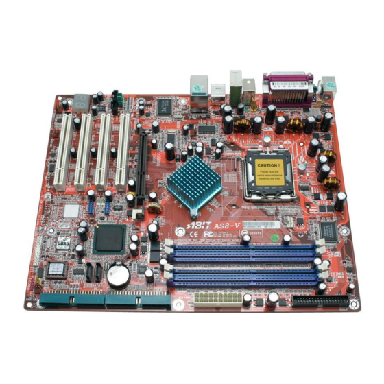
Page 7: Layout Diagram (As8 And As8-G)
Hardware Setup 1-2. Layout Diagram (AS8 and AS8-G) User’s Manual... -
Page 8: Layout Diagram (As8-V)
Chapter 2 1-3. Layout Diagram (AS8-V) AS8 Series... -
Page 9: Chapter 2. Hardware Setup
OK before putting the chassis back on. ATTENTION: To prevent shorting the PCB circuit, please REMOVE the metal studs or spacers if they are already fastened on the chassis base and are without mounting-holes on the motherboard to align with. User’s Manual... -
Page 10: Install Cpu, Heatsink And Fan Assembly
3. Use your right thumb on the bottom-right side of the load plate and lift it up to fully open position. AS8 Series 4. Use your right thumb and forefinger to grasp the CPU package. Be sure to grasp on the edge of the substrate, and face the Pin-1 indicator toward the bottom-left side. - Page 11 9. Place the heatsink and fan assembly onto the socket. Align the four fasteners toward the four mounting holes on the motherboard. For detailed information on how to install your heatsink and fan assembly, please refer to the instruction manual came packed with the heatsink and fan assembly you bought.
-
Page 12: Install System Memory
2-3. Install System Memory This motherboard provides four 184-pin DDR DIMM slots for Single/Dual Channel DDR 400/333/266 memory modules with memory expansion size up to 4GB. To reach the performance of Dual Channel DDR, the following rules must be obeyed: •... - Page 13 Hardware Setup Power off the computer and unplug the AC power cord before installing or removing memory modules. 1. Locate the DIMM slot on the board. 2. Hold two edges of the DIMM module carefully, keep away connectors. 3. Align the notch key on the module with the rib on the slot.
-
Page 14: Connectors, Headers And Switches
WARNING: Always power off the computer and unplug the AC power cord before adding or removing any peripheral or component. Failing to so may cause severe damage to your motherboard and/or peripherals. Plug in the AC power cord only after you have carefully checked everything. -
Page 15: Fan Power Connectors
Hardware Setup (2). FAN Power Connectors These connectors each provide power to the cooling fans installed in your system. • CPUFAN1: CPU Fan Power Connector • NBFAN1: Chipset Fan Power Connector • SYSFAN1: System Fan Power Connector • AUXFAN1, AUXFAN2: Auxiliary Fan Power Connector WARNING: These fan connectors are not jumpers. -
Page 16: Cmos Memory Clearing Header
• Pin 2-3 shorted: Clear CMOS memory. WARNING: Turn the power off first (including the +5V standby power) before clearing the CMOS memory. Failing to do so may cause your system to work abnormally or malfunction. AS8 Series Chapter 2... -
Page 17: Wake-Up Header
Hardware Setup (4). Wake-up Header These headers use a jumper cap to enable/disable the wake-up function. • PS2-PWR1: Pin 1-2 shorted (default): Disable wake-up function support at Keyboard/Mouse port. Pin 2-3 shorted: Enable wake-up function support at Keyboard/Mouse port • USB-PWR1: Pin 1-2 shorted (default): Disable wake-up function support at USB1 port. -
Page 18: Front Panel Audio Connection Header
• To use the audio connector at rear panel, disconnect the extension cable, attach the jumpers back at pin 5-6, and pin 9-10 (default setting). AS8 Series Pin Assignment Audio Mic. Audio Mic. Bias... -
Page 19: Front Panel Switches & Indicators Headers
Hardware Setup (6). Front Panel Switches & Indicators Headers This header is used for connecting switches and LED indicators on the chassis front panel. Watch the power LED pin position and orientation. The mark “+” align to the pin in the figure below stands for positive polarity for the LED connection. -
Page 20: Additional Ieee1394 Port Headers (For As8 And As8-G)
2-12 (7). Additional IEEE1394 Port Headers (For AS8 and AS8-G) These headers each provide one additional IEEE1394 port connection through an extension cable and bracket. (8). Additional USB Port Headers These headers each provide 2 additional USB 2.0 ports connection through an USB cable designed for USB 2.0 specifications. -
Page 21: Guru Clock Connection Header
2-13 (9). GURU Clock Connection Header This header is reserved for connecting ABIT’s exclusive GURU Clock. (10). System Management Bus Headers This header is reserved for system management bus (SM bus). The SM bus is a specific implementation of an I C bus. -
Page 22: Internal Audio Connectors
2-14 Chapter 2 (11). Internal Audio Connectors These connectors connect to the audio output of internal CD-ROM drive or add-on card. AS8 Series... -
Page 23: Floppy And Ide Disk Drive Connectors
Hardware Setup 2-15 (12). Floppy and IDE Disk Drive Connectors The FDC1 connector connects up to two floppy drives with a 34-wire, 2-connector floppy cable. Connect the single end at the longer length of ribbon cable to the FDC1 on the board, the two connectors on the other end to the floppy disk drives connector. -
Page 24: Post Code Display
POST Code in address 80h to find out where the problem lies. This LED device also displays the “POST” Code of AC2003, an “uGuru” chipset developed exclusively by ABIT computer. NOTE: The decimal point lights up when executing the AC2003 POST action. -
Page 25: Serial Ata Connectors
Hardware Setup (14). Serial ATA Connectors These connectors are provided to attach one Serial ATA device at each channel via Serial ATA cable. (15). Status Indicators • D12 (5VSB): This LED lights up when the power supply is connected with power source. •... -
Page 26: Back Panel Connectors
F.L./F.R. (Front Left / Front Right): Connects to the front left and front right channel in the 5.1-channel or regular 2-channel audio system. • IEEE1394: Connects to devices of IEEE1394 protocol. (For AS8 and AS8-G) • LAN: Connects to Local Area Network. -
Page 27: Chapter 3. Bios Setup
BIOS Setup Chapter 3. BIOS Setup This motherboard provides a programmable EEPROM that you can update the BIOS utility. The BIOS (Basic Input/Output System) is a program that deals with the basic level of communication between processor and peripherals. Use the BIOS Setup program only when installing motherboard, reconfiguring system, or prompted to “Run Setup”. -
Page 28: Μguru Utility
This item displays the CPU model name installed on this motherboard. Frequency: This item displays the processor speed of the CPU installed on this motherboard. CPU Operating Speed: This item displays the CPU operating speed according to the type and speed of your CPU. You can also select the [User Define] option to enter the manual option. - Page 29 BIOS Setup External Clock: This item selects the external clock frequency. Due to the specification limit of the CPU you installed, the speed you set over its standard bus speed is supported, but not guaranteed. Multiplier Factor: This item displays the multiplier factor for the CPU you installed. N/B Strap CPU As: This item sets the external hardware reset strap assigned to MCH (Memory Controller Hub).
- Page 30 These items display the power cycle statistics for each element. ABIT EQ: Click right-arrow <→> key to switch from OC Guru setup menu to ABIT EQ setup menu: ABIT EQ Beep Control: This item allows you to enable or disable ABIT EQ Beep Control function.
-
Page 31: Temperature Monitoring
BIOS Setup Temperature Monitoring: Click <Enter> key to enter its submenu: CPU Temperature/System Temperature/PWM Temperature: These items display the temperature of CPU, System, and Power Module. Shutdown Enable: Use <Space> key to enable system shutdown function. If the CPU/System/PWM’s temperature exceeds the shutdown temperature limit, the system would shutdown automatically. - Page 32 Use <Space> key to enable warning beeps function. If the voltage of corresponding element is higher/lower than the high/low limit, warning beeps will sound. High/Low Limit: These items set the high and low voltage limit. NOTE: The value of high limit must be set above the one of low limit. AS8 Series Chapter 3...
-
Page 33: Fan Speed Monitoring
BIOS Setup Fan Speed Monitoring: Click <Enter> key to enter its submenu: CPU/NB/SYS/AUX1/AUX2 FAN Speed: These items display the speed of the fans connected to CPU, NB, SYS, AUX1 and AUX2 FAN headers. Shutdown Enable: Use <Space> key to enable system shutdown function. Once the system has detected that the fan speed is lower than the low limit value, system will shutdown automatically. - Page 34 DC Fan Voltage High/Low: These items set the high and low voltage limit that you want to provide the fan with. NOTE: The value of high limit must be set above the one of low limit. AS8 Series Chapter 3...
-
Page 35: Standard Cmos Features
BIOS Setup 3-2. Standard CMOS Features This section contains the basic configuration parameters of the BIOS. These parameters include date, hour, VGA card, FDD, and HDD settings. Date (mm:dd:yy): This item sets the date you specify (usually the current date) in the format of [Month], [Date], and [Year]. Time (hh:mm:ss): This item sets the time you specify (usually the current time) in the format of [Hour], [Minute], and [Second]. - Page 36 This item allows you to use “3 Mode Floppy Drive” in Japanese computer system by selecting drive A, B, or both. Leave this item to its default [Disabled] setting if you are not using this Japanese standard floppy drive. Halt On: This item determines whether the system stops if an error is detected during system boot-up. AS8 Series...
- Page 37 Base Memory: This item displays the amount of base memory installed in the system. The value of the base memory is typically 640K for system with 640K or more memory size installed on the motherboard. Extended Memory: This item displays the amount of extended memory detected during system boot-up.
-
Page 38: Advanced Bios Features
When set to [Disabled], this NX features flag will be forced to return to 0. Back to Advanced BIOS Features Setup Menu: Hyper-Threading Technology This item is used to enable the functionality of the processor with Hyper-Threading Technology and will appear only when using such processor. AS8 Series Chapter 3... - Page 39 BIOS Setup 3-13 The Hyper-Threading Technology helps your PC work more efficiently by maximizing processor resources and enabling a single processor to run two separate threads of software simultaneously, bringing forth greater performance and system responsiveness when running multiple applications at once.
- Page 40 CMOS before you can start up the system. But by doing this, you will have to reset all previously set options. MPS Version Ctrl For OS: This item specifies which version of MPS (Multi-Processor Specification) this motherboard will use. Leave this item to its default setting. Report No FDD For OS: When set to [Yes], this item allows you to run some older operating system without floppy disk drive.
-
Page 41: Advanced Chipset Features
BIOS Setup 3-4. Advanced Chipset Features DRAM Timing Selectable: This item sets the optimal timings for the following four items, depending on the memory module you are using. The default setting “By SPD” configures these four items by reading the contents in the SPD (Serial Presence Detect) device. - Page 42 This item determines the timing of DRAM Read Delay. Read delay Adjust(tRDA): This item determines to adjust the timing of DRAM Read Delay. Command Per Clock(CPC): This item determines the address command timing according to the DRAM strobe clock. AS8 Series Chapter 3...
-
Page 43: Integrated Peripherals
BIOS Setup 3-17 3-5. Integrated Peripherals OnChip IDE Device: Click <Enter> key to enter its submenu: IDE Bus Master: This option enables or disables the IDE bus mastering capability under the DOS environment. OnChip IDE-1 Controller: This item allows you to enable or disable the primary and secondary IDE controller. Select [Disabled] if you want to add a different hard drive controller. - Page 44 Enhanced IDE-4 Master IDE-1 Master IDE-1 Slave Combined IDE-2 Master IDE-2 Slave AS8 Series Serial ATA Port 2 Description (SATA2) • SATA1 serves as IDE-3 Master • SATA2 serves as IDE-4 Master IDE-4 Master • OnChip IDE-1 and IDE-2 controller enabled •...
- Page 45 BIOS Setup IDE-1 Master SATA Only IDE-2 Master OnChip PCI Device: Click <Enter> key to enter its submenu: OnChip USB Controller: This option enables or disables the USB controller. USB 2.0 Controller: This option enables or disables the USB 2.0 controller. USB Keyboard Support Via: This item allows you to select [BIOS] for using USB keyboard in DOS environment, or [OS] in OS environment.
-
Page 46: Superio Device
[EPP]: (Enhanced Parallel Port) Allows bi-directional parallel port operation at maximum speed. [ECP]: (Extended Capabilities Port) Allows bi-directional parallel port operation at a speed faster than the normal mode’s data transfer rate. [ECP+EPP]: Allows parallel port operation at ECP and EPP mode. AS8 Series... -
Page 47: Power Management Setup
This item selects the DMA channel of the parallel port. Onboard PCI Device: Click <Enter> key to enter its submenu: IEEE 1394 Controller: (For AS8 and AS8-G) This option enables or disables the IEEE 1394 controller. Onboard LAN Controller: This option enables or disables the LAN controller. - Page 48 This item powers on the system by pressing <Ctrl> key plus one of each function key (<F1> ~ <F12>) simultaneously. Restore On AC Power Loss: This item selects the system action after an AC power failure. [Power Off]: When power returns after an AC power failure, the system’s power remains off. You must AS8 Series Chapter 3...
- Page 49 BIOS Setup press the Power button to power-on the system. [Power On]: When power returns after an AC power failure, the system’s power will be powered on automatically. [Last State]: When power returns after an AC power failure, the system will return to the state where you left off before power failure occurs.
-
Page 50: Pnp/Pci Configurations
This item sets each system interrupt to either [PCI Device] or [Reserved]. PCI/VGA Palette Snoop: This item determines whether the MPEG ISA/VESA VGA cards can work with PCI/VGA or not. [Enabled]: MPEG ISA/VESA VGA cards work with PCI/VGA. [Disabled]: MPEG ISA/VESA VGA cards do not work with PCI/VGA. AS8 Series... - Page 51 BIOS Setup PCI Latency Timer(CLK): This item controls how long each PCI device can hold the bus before another takes over. When set to higher values, every PCI device can conduct transactions for a longer time and thus improve the effective PCI bandwidth.
-
Page 52: Load Fail-Safe Defaults
This option protects the BIOS configuration or restricts access to the computer itself. 3-11. Save & Exit Setup This option saves your selections and exits the BIOS setup menu. 3-12. Exit Without Saving This option exits the BIOS setup menu without saving any change. AS8 Series... -
Page 53: Appendix A. Install Intel Chipset Software Utility
Install Intel Chipset Software Utility Appendix A. Install Intel Chipset Software Utility NOTE: Please install this Intel Chipset driver first after having installed the Windows operating system. The installation procedures and screen shots in this section are based on the Windows XP operating system. - Page 54 AS8 Series AS8 Series Appendix A Appendix A...
-
Page 55: Appendix B. Install Intel Application Accelerator Raid (For As8 And As8-G
Install Intel Application Accelerator RAID (For AS8 only) Appendix B. Install Intel Application Accelerator RAID (For AS8 and AS8-G) The installation procedures and screen shots in this section are based on the Windows XP operating system. For other operating systems, please follow its on-screen instructions. - Page 56 Click [Next]. Click [Finish] to complete setup. AS8 Series Appendix B...
- Page 57 Install Intel Application Accelerator RAID (For AS8 only) Intel Serial ATA RAID Configuration Utility The on-chip Serial ATA RAID supports the Stripe (RAID 0) and Mirror (RAID 1) RAID set. For the striped RAID set, the identical drives can read and write data in parallel to increase performance.
- Page 58 (The entire partition configuration will be deleted too.) AS8 Series Reset Disks to Non-RAID This item allows you to reset all RAID data. Type <Y> if you want to reset all RAID data.
-
Page 59: Appendix C. Install Audio Driver
Install Audio Driver Appendix C. Install Audio Driver The installation procedures and screen shots in this section are based on the Windows XP operating system. For other operating systems, please follow its on-screen instructions. Insert the Driver & Utility CD into the CD-ROM drive, should... - Page 60 AS8 Series AS8 Series Appendix C Appendix C...
-
Page 61: Appendix D. Install Lan Driver
Install LAN Driver Appendix D. Install LAN Driver The installation procedures and screen shots in this section are based on the Windows XP operating system. For other operating systems, please follow its on-screen instructions. Insert the Driver & Utility CD into the CD-ROM drive, should... - Page 62 Appendix D AS8 Series...
-
Page 63: Appendix E. Install Usb 2.0 Driver
Install USB 2.0 Driver Appendix E. Install USB 2.0 Driver NOTE: The installation for USB 2.0 driver for Windows XP or Windows 2000 is currently available by updating the latest Service Pack from Microsoft’s web site. User’s Manual... - Page 64 AS8 Series AS8 Series Appendix E Appendix E...
-
Page 65: Appendix F. Install Abit Μguru Utility
CD to enter the installation menu. After entering the installation menu, move your curser to [ABIT Utility] tab. Click [ABIT uGuru]. The following screen appears. 3. Click [Next]. 4. Click [Next]. - Page 66 Appendix F AS8 Series...
-
Page 67: Appendix G. Post Code Definition
POST Code Definition Appendix G. POST Code Definition AWARD POST Code Definition: POST Description (hex) Test CMOS R/W functionality Early chipset initialization: -Disable shadow RAM -Disable L2 cache (socket 7 or below) -Program basic chipset registers Detect memory -Auto-detection of DRAM size, type and ECC -Auto-detection of L2 cache (socket 7 or below) Expand compressed BIOS code to DRAM Call chipset hook to copy BIOS back to E000 &... - Page 68 4. On MP platform, adjust the cacheable range to smaller one in case the cacheable ranges between each CPU are not identical Initialize USB Test all memory (clear all extended memory to 0) Clear password according to H/W jumper (Optional) AS8 Series Appendix G...
- Page 69 POST Code Definition Display number of processors (multi-processor platform) Display PnP logo Early ISA PnP initialization -Assign CSN to every ISA PnP device Initialize the combined Trend Anti-Virus code (Optional Feature) Show message for entering AWDFLASH.EXE from FDD (optional) 1. Initialize Init_Onboard_Super_IO 2.
- Page 70 Update keyboard LED & typematic rate 1. Build MP table 2. Build & update ESCD 3. Set CMOS century to 20h or 19h 4. Load CMOS time into DOS timer tick 5. Build MSIRQ routing table Boot attempt (INT 19h) AS8 Series Appendix G...
- Page 71 POST Code Definition AC2003 POST Code Definition: POST Description (hex) 8.1. Start power on sequence 8.2. Enable ATX power supply 8.3. ATX power supply ready 8.4. DDR voltage ready 8.5. Setup PWM for CPU core voltage 8.6. Assert PWM for CPU core voltage 8.7.
- Page 72 Appendix G AS8 Series...
-
Page 73: Appendix H. Troubleshooting (Need Assistance
Appendix H. Troubleshooting (Need Assistance?) Q & A: Q: Do I need to clear the CMOS before I use a new motherboard to assemble my new computer system? A: Yes, we highly recommend that you clear the CMOS before installing a new motherboard. Please move the CMOS jumper from its default 1-2 position to 2-3 for a few seconds, and then back. - Page 74 If you have a problem during operation, in order to help our technical support personnel quickly determine the problem with your motherboard and give you the answers you need, before filling in the technical support form, eliminate any peripheral that is not related to the problem, and indicate it on the form.
- Page 75 To fill in this “Technical Support Form”, refer to the step-by-step instructions given below: . MODEL: Note the model number given in your user’s manual. Example: AS8, AS8-V, AS8-G . Motherboard model number (REV): Note the motherboard model number labeled on the motherboard as “REV:*.**”. Example: REV: 1.02 .
-
Page 76: Technical Support Form
Contact Person: E-mail Address: Model Motherboard Model No. OS/Application Hardware Name IDE1 IDE2 IDE1 CD-ROM-Drive IDE2 System Memory ADD-ON CARD Problem Description: AS8 Series Technical Support Form Phone Number: Fax Number: BIOS ID # DRIVER REV Brand Specifications Appendix H... -
Page 77: Appendix I. How To Get Technical Support
Also please make sure you have the latest drivers from your peripheral cards makers! 3. Check the ABIT Technical Terms Guide and FAQ on our Website. We are trying to expand and make the FAQs more helpful and information rich. Let us know if you have any suggestions. - Page 78 They should have reasonable return or refund policies. How they serve you is also a good reference for your next purchase. 6. Contacting ABIT. If you feel that you need to contact ABIT directly you can send email to the ABIT technical support department. First, please contact the support team for the branch office closest to you.
- Page 79 ABIT Computer (U.K.) Corporation Ltd. Unit 3, 24-26 Boulton Road, Stevenage, Herts SG1 4QX, UK Tel: 44-1438-228888 Fax: 44-1438-226333 E-mail: sales@abitcomputer.co.uk AMOR Computer B.V. (ABIT's European Office) Jan van Riebeeckweg 15, 5928LG, Venlo, The Netherlands Tel: 31-77-3204428 Fax: 31-77-3204420 Sales: sales@abit.nl Web Site: http://www.abit.nl...
- Page 80 8. Reporting Compatibility Problems to ABIT. Because of tremendous number of email messages we receive every day, we are forced to give greater weight to certain types of messages than to others. For this reason, any compatibility problem that is reported to us, giving detailed system configuration information and error symptoms will receive the highest priority.